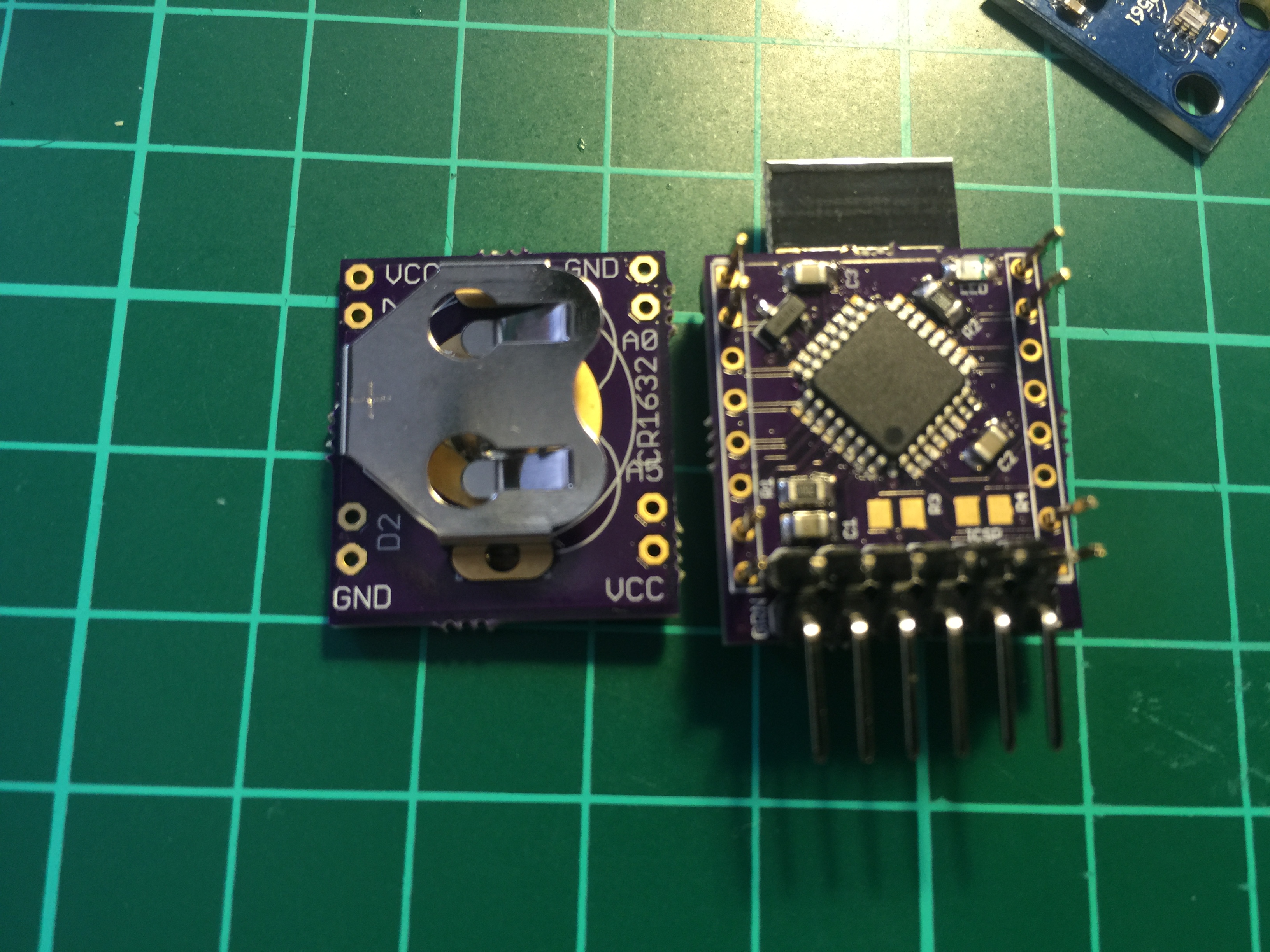
💬 Stamp size MySensor node
-
@GertSanders Gert, what pins_arduino.h are you using for this board please? Can you post it here?
And here is a ZIP file with my complete atmega328p definitions
-
And here is a ZIP file with my complete atmega328p definitions
@GertSanders Many thanks for your help. This is probably my bad luck, but I have mixed up C1 and R1 mounting them vertically (not horizontally). What a stupid mistake really given that I have checked it a few times. Anyway, now everything is working.
FYG, I looked at your pins_arduino.h - this is a standard one and it is not correct. I corrected the following entries:
static const uint8_t SS = 14; static const uint8_t MOSI = 15; static const uint8_t MISO = 16; static const uint8_t SCK = 17; static const uint8_t SDA = 27; static const uint8_t SCL = 28; #define LED_BUILTIN 8 static const uint8_t A0 = 23; static const uint8_t A1 = 24; static const uint8_t A2 = 25; static const uint8_t A3 = 26; static const uint8_t A4 = 27; static const uint8_t A5 = 28; static const uint8_t A6 = 19; static const uint8_t A7 = 22; -
@GertSanders Many thanks for your help. This is probably my bad luck, but I have mixed up C1 and R1 mounting them vertically (not horizontally). What a stupid mistake really given that I have checked it a few times. Anyway, now everything is working.
FYG, I looked at your pins_arduino.h - this is a standard one and it is not correct. I corrected the following entries:
static const uint8_t SS = 14; static const uint8_t MOSI = 15; static const uint8_t MISO = 16; static const uint8_t SCK = 17; static const uint8_t SDA = 27; static const uint8_t SCL = 28; #define LED_BUILTIN 8 static const uint8_t A0 = 23; static const uint8_t A1 = 24; static const uint8_t A2 = 25; static const uint8_t A3 = 26; static const uint8_t A4 = 27; static const uint8_t A5 = 28; static const uint8_t A6 = 19; static const uint8_t A7 = 22;@alexsh1
OK, I will check also on my side :-) Thanks for the feedback. -
@alexsh1
OK, I will check also on my side :-) Thanks for the feedback.@GertSanders No worries! And signing works flawlessly on this node as well with ATSHA204A by the way :)
-
@alexsh1
Double plus good !
As I have no signing capability on my raspberry-turned-gateway I'm glad the hard work to simplify signing was done so well by @tbowmo and @Anticimex. Even without testing it I could assume it would work. -
@alexsh1
Double plus good !
As I have no signing capability on my raspberry-turned-gateway I'm glad the hard work to simplify signing was done so well by @tbowmo and @Anticimex. Even without testing it I could assume it would work.@GertSanders You are welcome :) Btw, if you just patch in support to generate random data for a nonce, you can use the soft signing backend on rPi.
-
@GertSanders You are welcome :) Btw, if you just patch in support to generate random data for a nonce, you can use the soft signing backend on rPi.
@Anticimex
Well that sounds simple, but I'm more a hardware contributer, this is beyond my capabilities :-), especially in unix arena. I manage software developers for a living, so I know how much I do not know. -
Hello guys,
I am about to solder first PCB of this version. Just to be 100% sure, regarding C4 - what is the best value to use 1uF or 10uF, because I can see we can choose.
Regards,
MaciekBetter to use 10uF. The schematic needs to be updated (still shows 1uF, I use 10uF now).
-
Thank you for the update,
Last part what I am missing is battery holder. I was trying to search it in many stores located in my country however I was not able to get it. Is there any internet shop when I can buy online? I have one workaround to soldier different CR battery holder and connect via wires.RPI2 + RFLink + PiFace D2 + Aeon Z-Wave Gen5 + Foscams FI9821P&R2 + MySensors + UPS APC Back-UPS 950VA
RPI2 + RFXtrx433e + Foscams FI9821P + MySensors + UPS APC Back-UPS 950VA
RPIB+ + TP-Link MR3420 + Huawei E173 GarageDomoticz :) -
Thank you for the update,
Last part what I am missing is battery holder. I was trying to search it in many stores located in my country however I was not able to get it. Is there any internet shop when I can buy online? I have one workaround to soldier different CR battery holder and connect via wires. -
@macieiks I bought the battery holder on http://www.ebay.co.uk/
-
@AWI I just put a link to an eBay. You put "Keystone 3013" in the search and hit search :-)
-
@alexsh1 do you plan to use this so small coincell with rfm69? very curious to see results regarding internal res during RX-Tx times...1.8V brownout should not be far i think..or maybe not :) because the voltage won't stay at 3v ;) but to counter effect, a nice capa at input with a current limiting resistor could help. reading/waiting voltage stabilize before transmitting can help too (I'm doing this with some CR2032 based nodes)
-
-
@alexsh1 do you plan to use this so small coincell with rfm69? very curious to see results regarding internal res during RX-Tx times...1.8V brownout should not be far i think..or maybe not :) because the voltage won't stay at 3v ;) but to counter effect, a nice capa at input with a current limiting resistor could help. reading/waiting voltage stabilize before transmitting can help too (I'm doing this with some CR2032 based nodes)
@scalz Yes, that's the plan, but I think I'll come across many difficulties. For now I have the nrf24l01+ version fully working. And started scratching the surface with RFM69. This is nrf24l01+ SMD version and swapping it for RFM69 is not going to be easy. So far I have not seen any adapters for the SMD version.
-
I have just updated a stamp size node to MySensors 2.1.1 and had to include the following into the sketch:
#define MY_RF24_CE_PIN 9
#define MY_RF24_CS_PIN 10
#define MY_SOFTSPI
#define MY_SOFT_SPI_SCK_PIN 13
#define MY_SOFT_SPI_MISO_PIN 12
#define MY_SOFT_SPI_MOSI_PIN 11The fist two lines are not required (it is in the MyConfig.h), but for me to understand how nrf24l01+ is connected.
I hope it helpsRegards
Alex -
Hi @GertSanders, @alexsh1
I'm considering to build a few nodes with this design, could anyone that have done and tested these give some feedback on how it work? Battery life etc. In my case I will mostly use it as window/door sensor and water leakage sensor so it would not send data to frequently.
Thanks for any input.
Hello! It looks like you're interested in this conversation, but you don't have an account yet.
Getting fed up of having to scroll through the same posts each visit? When you register for an account, you'll always come back to exactly where you were before, and choose to be notified of new replies (either via email, or push notification). You'll also be able to save bookmarks and upvote posts to show your appreciation to other community members.
With your input, this post could be even better 💗
Register Login