Problem with Wind Speed sensor
-
Thanks for you're reply. On the ebay website at the product description, it is said: "Supply voltage: DC 12-24 V", so therefore I thought I needed a 12V powersupply to power this device
I use a nano board, so I can attach a 5V to it, I will give this a try. I still need to find out first if it is broken basically :) But a few things that worries me regarding this setup:
- The picture on the ebay site shows 4 cables coming out of the device. I only see three :) Regarding the other sketches, this seems to be OK, because A1 is only attached.. but I am not sure
- When I run the sketch and I just read out the Analog pin 1, I always get data. The device doesn't needs to be attached basically. So I really don't get how the Analog 1 pin should work and why I get data when nothing is attached? I used the sketch of this topic: https://forum.mysensors.org/topic/2856/wind-speed-sensor-node/21 using the last reply. Only I deleted the direction and gust values, because I can only measure speed I think.
Can you give me a heads up? How should you think I need to connect it? And how I must adjust the sketch in order to get the data?
-
@AWI said:
@rnollen Your values could be from a floating input. So like @Yveaux suggested the wind sensor can have an open collector output. Best to try with a multimeter first. You can connect a 10 - 100k resistor from the output to Vcc and see if you get a pulse output when rotating.
@all thanks for all the replies. I did send an e-mail to that ebay supplier. :)
@AWI: I have a 100 ohm resistor. Connect this to my breadboard, but don't know how to connect this then to an arduino? The windmeter has three cables: black / red and yellow. The yellow line is the data line and black/red are power and ground? I have a multimeter, but not sure how to use it for this purpose :)
@rnollen I think you can just assume that red =positive, black = gnd and yellow = signal.
You should connect the resistor between yellow and red if you assume an open collector output. Then power the sensor on black and red.Connect your multimeter (in volt position)(just noticed you have one) to yellow and ground and rotate the sensor slowly. A 100 ohm resistor will do for testing. -
@rnollen I think you can just assume that red =positive, black = gnd and yellow = signal.
You should connect the resistor between yellow and red if you assume an open collector output. Then power the sensor on black and red.Connect your multimeter (in volt position)(just noticed you have one) to yellow and ground and rotate the sensor slowly. A 100 ohm resistor will do for testing.@AWI said:
@rnollen I think you can just assume that red =positive, black = gnd and yellow = signal.
You should connect the resistor between yellow and red if you assume an open collector output. Then power the sensor on black and red.Connect your multimeter (in volt position)(just noticed you have one) to yellow and ground and rotate the sensor slowly. A 100 ohm resistor will do for testing.Thanks. I did a quick test. Grabbed my multimeter and set it on the 20v. (2v gives me an error). Connected it like you have said, using the resistor. Used the ground and 5v of my Arduino nano as power.
When I do not rotate; I get 4.54V on the yellow and black line. When I start rotating, it is less.. mostly around 3. But it jumps around, but always less then the 4.6 when I start to rotate. I cannot say that rotating faster gives me another or different value, I think it will go to the 3.So any idea :)
-
@AWI said:
@rnollen I think you can just assume that red =positive, black = gnd and yellow = signal.
You should connect the resistor between yellow and red if you assume an open collector output. Then power the sensor on black and red.Connect your multimeter (in volt position)(just noticed you have one) to yellow and ground and rotate the sensor slowly. A 100 ohm resistor will do for testing.Thanks. I did a quick test. Grabbed my multimeter and set it on the 20v. (2v gives me an error). Connected it like you have said, using the resistor. Used the ground and 5v of my Arduino nano as power.
When I do not rotate; I get 4.54V on the yellow and black line. When I start rotating, it is less.. mostly around 3. But it jumps around, but always less then the 4.6 when I start to rotate. I cannot say that rotating faster gives me another or different value, I think it will go to the 3.So any idea :)
@rnollen can you get it to a stable less than 3v when rotating.? If you can not get it stable than I there is a chance a serial protocol like "onewire" is used. Then you need a clue from the supplier. If you have stable outputs when rotating very slowly it is probably a pulse train which you can count.
-
@rnollen can you get it to a stable less than 3v when rotating.? If you can not get it stable than I there is a chance a serial protocol like "onewire" is used. Then you need a clue from the supplier. If you have stable outputs when rotating very slowly it is probably a pulse train which you can count.
@AWI said:
@rnollen can you get it to a stable less than 3v when rotating.? If you can not get it stable than I there is a chance a serial protocol like "onewire" is used. Then you need a clue from the supplier. If you have stable outputs when rotating very slowly it is probably a pulse train which you can count.
Yes, It is stable when you rotate it. Around the 3V. But how can I count it then?
-
Thanks; but how to go further from here then :) Is there a way to create a sketch for this device? And how to attach it to a Nano board?
I got a manual from the supplier: https://1drv.ms/w/s!AmsPyx0xoB6jjYo0PZZRazdA3-vPpw for this device. But I already see a difference with the wires :) But to give it a start then, according to the manual it counts the pulses and that gives a windspeed :)
@rnollen Hi, the manual is a bit confusing in that it mentions a "serial protocol" and also a table is mentioned with voltages and wind speed. As yours iw 3 wire we can assume it is not a RS485 output.
Then there are you need to dertermine what kind of output it is either NPN or PNP. : PNP needs a "pull down" resistor. NPN needs a "pull up". resistor..Best thing is to test the different options with the volt meter.
According to the table the "average" voltage should vary with the rotating spreed.
Note that I make a lot of assumptions.... but: If you get a voltage on your meter that changes with the rotating spreed than it is time to connect the nan. With the assumption that there are pulses, best thing is to write a routine which counts the pulses in a certain time frame e.g 10 secs. (connect the nano with a either a digital or analog pin, but read with digitalread(),. There should be many examples on the web.
Have fun
-
@AWI . I will try to find out. But for the record later, can I simply connect the 5V, ground and the Yellow dataline directly to the arduino ? Or do I still need a resistor somewhere?
Then I will try to find I sketch to read the digital pin. Can i maybe use other pulse sketches as an example?
I will do the Volt test, I know that the volt test remains the same when I rotate on the same speed. Don't know for sure, if I rotate faster if the volt's are the same then as before. I thought not, but I will test later tonight. -
@AWI . I will try to find out. But for the record later, can I simply connect the 5V, ground and the Yellow dataline directly to the arduino ? Or do I still need a resistor somewhere?
Then I will try to find I sketch to read the digital pin. Can i maybe use other pulse sketches as an example?
I will do the Volt test, I know that the volt test remains the same when I rotate on the same speed. Don't know for sure, if I rotate faster if the volt's are the same then as before. I thought not, but I will test later tonight.@rnollen If you keep the voltage at 5v you can directy connect to the arduino pin. You still need a pull-up/down resistor though.
pin D13 on the nano has a LED connected to it. It may help you in observing what is going on. A LED is much faster than a volt meter..
-
@rnollen If you keep the voltage at 5v you can directy connect to the arduino pin. You still need a pull-up/down resistor though.
pin D13 on the nano has a LED connected to it. It may help you in observing what is going on. A LED is much faster than a volt meter..
@AWI said:
@rnollen If you keep the voltage at 5v you can directy connect to the arduino pin. You still need a pull-up/down resistor though.
pin D13 on the nano has a LED connected to it. It may help you in observing what is going on. A LED is much faster than a volt meter..
Sorry for all the questions :) But I am a noob on this matter. I do know something of scripting, but electronics is not something where I am familiar with.
But to summarize then how to connect it; The yellow line, will go through a resistor (which one?) and that is connected to D13. Black is Ground, Red is 5 Volt? Is this correct? And is this setup only for testing or also as the final solution later on, because the D13 is also used for the radio? Problem is: I don't know exactly what a LED is in you're example :)Edit-> Also send questions to the supplier. Maybe he can gives me an answer if it is PNP or NPN device. Also asked for schematics and how to calculate the pulses.
-
When I use the volt meter and I rotate, then the volts are pretty much the same. Rotating faster, doesn't give me higher values.
As a test I have attached it to my Arduino nano using a 10k Pullup resistor. Found a little example sketch regarding the LED on the arduino site. As the very first test I can see the light bling on the arduino when I rotate the windmeter. Rotating it harder will make the light bling faster, rotating slower and it blings slowly. So the pulses seems to come through.But now, I need a vary small and basic way to start counting the pulses when it rotates. I have tried to create a very small sketch (using an example of the Arduino website). But that is not working OK. Tried to modify the examples for powermeter and watermeter which are also pulse sketches, but at this stage it has too much code.
Does anyone have a very small example sketch to start with for my setup? -
@rnollen Hi, the manual is a bit confusing in that it mentions a "serial protocol" and also a table is mentioned with voltages and wind speed. As yours iw 3 wire we can assume it is not a RS485 output.
Then there are you need to dertermine what kind of output it is either NPN or PNP. : PNP needs a "pull down" resistor. NPN needs a "pull up". resistor..Best thing is to test the different options with the volt meter.
According to the table the "average" voltage should vary with the rotating spreed.
Note that I make a lot of assumptions.... but: If you get a voltage on your meter that changes with the rotating spreed than it is time to connect the nan. With the assumption that there are pulses, best thing is to write a routine which counts the pulses in a certain time frame e.g 10 secs. (connect the nano with a either a digital or analog pin, but read with digitalread(),. There should be many examples on the web.
Have fun
@AWI said:
..... There should be many examples on the web.Have fun
Unfortunately I cannot find any working example code. Found all kind of stuff on the internet, but nothing that will give me some valuable data.
I think that the examples on the internet mostly uses an pull up anemometer, as far as I can see the Arduino Nano also have a internal one which you can activate on the sketch. But basically, when I use a resistor, which is connected on the yellow and red wire, I am still stuck on the sketch I cannot find something desent (and small), that gives me something valuable. I now know why the windmeter is not an example on the Mysensors site :) Way to difficult :). -
@AWI said:
..... There should be many examples on the web.Have fun
Unfortunately I cannot find any working example code. Found all kind of stuff on the internet, but nothing that will give me some valuable data.
I think that the examples on the internet mostly uses an pull up anemometer, as far as I can see the Arduino Nano also have a internal one which you can activate on the sketch. But basically, when I use a resistor, which is connected on the yellow and red wire, I am still stuck on the sketch I cannot find something desent (and small), that gives me something valuable. I now know why the windmeter is not an example on the Mysensors site :) Way to difficult :).@rnollen It shouldn't be so complicated.. there are a many ways to do it. Start in the learning curve with the most simple method of counting pulses using the arduino builtin method pulseIn(). (non MySensors, basic arduino). You should be able to see the pulse frequency on the serial port when turning the rotor.
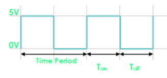
const int anemometerPin = 4 ; // wherever you connected the anemometer unsigned long timePeriod = 0; unsigned long timeon = 0; unsigned long timeoff =0; void setup() { pinMode(anemometerPin, INPUT_PULLUP); Serial.begin(9600); } void loop() { timeon = pulseIn(anemometerPin,HIGH); // Measured Time On timeoff = pulseIn(anemometerPin,LOW); // Measure Time Off timePeriod = timeon + timeoff; // total period = on + off float frequency = 1000000.0/timePeriod; // calculate the frequency Serial.println(frequency); delay(1000); } -
@AWI Thanks, I will give it a try. Today I also received some additional info. The device is a NPN model. Type 12CM, according to the supplier it is 12 pulses for 1m/s per second. But the manual says that this model is 10 pulses for 1m/s.
So basically I could now connect the device as NPN, only I need to find out how :)
-
@rnollen good news. Npn needs a pull-up so the sketch above should be able to do it. It uses the internal pull-up of the Arduino. I am curious to the outcome.
@AWI said:
@rnollen good news. Npn needs a pull-up so the sketch above should be able to do it. It uses the internal pull-up of the Arduino. I am curious to the outcome.
It does not work entirely correct I think. In the serial Monitor I see "Inf" as outcome of the sketch :( Don't see exactly where that is coming from :)
Maybe something wrong with the wiring? I Attached the 12V DC to red and blue. The Yellow, connected it to the breadboard and a cable from the D7 also to this connection. I took a 4.7K resistor, connected also to this group and the other side of this resistor I connected to the 5V of the Arduino? Is that correct?
When I remove the resistor: then this is my outcome of the sketch:
12.82
inf
inf
3.36
1.88
55.06
inf
37037.03
inf
333333.34
30.95
17.43
inf
142857.14
inf
125000.00
500000.00
500000.00
90909.10
500000.00
39.47
inf
250000.00
500000.00
inf
20.54
45.67
58823.53
inf
9.88
inf
inf
9.17
infThen I got some numbers, but what they mean :) The very high numbers are when rotating..
-
@AWI said:
@rnollen good news. Npn needs a pull-up so the sketch above should be able to do it. It uses the internal pull-up of the Arduino. I am curious to the outcome.
It does not work entirely correct I think. In the serial Monitor I see "Inf" as outcome of the sketch :( Don't see exactly where that is coming from :)
Maybe something wrong with the wiring? I Attached the 12V DC to red and blue. The Yellow, connected it to the breadboard and a cable from the D7 also to this connection. I took a 4.7K resistor, connected also to this group and the other side of this resistor I connected to the 5V of the Arduino? Is that correct?
When I remove the resistor: then this is my outcome of the sketch:
12.82
inf
inf
3.36
1.88
55.06
inf
37037.03
inf
333333.34
30.95
17.43
inf
142857.14
inf
125000.00
500000.00
500000.00
90909.10
500000.00
39.47
inf
250000.00
500000.00
inf
20.54
45.67
58823.53
inf
9.88
inf
inf
9.17
infThen I got some numbers, but what they mean :) The very high numbers are when rotating..
@rnollen the "inf" means infinite and is caused by a 0 division. You can try to remove the line starting with 'float' and print the time values.
I assume you changed the anemometer pin in the sketch to d7...?
And connected the gnd of 12v and 5v together? -
@rnollen the "inf" means infinite and is caused by a 0 division. You can try to remove the line starting with 'float' and print the time values.
I assume you changed the anemometer pin in the sketch to d7...?
And connected the gnd of 12v and 5v together?@AWI said:
@rnollen the "inf" means infinite and is caused by a 0 division. You can try to remove the line starting with 'float' and print the time values.
I assume you changed the anemometer pin in the sketch to d7...?I have did some additional testing. The DC12 is wrong I think, when I use that then the whole sketch does not give any values back. Now used the 5V of the arduino, then I got something readings using this sketch. I have added some additional serial print lines for logging. But when times are zero, then the frequency is INF and that happens when I don't rotate, so that looks OK I think
..
Timeon: 0
Timeoff: 0
TimePeriod: 0
Frequency: inf
Timeon: 0
Timeoff: 87951
TimePeriod: 87951
Frequency: 11.37
Timeon: 24222
Timeoff: 22899
TimePeriod: 47121
Frequency: 21.22
Timeon: 24960
Timeoff: 27680
TimePeriod: 52640
Frequency: 19.00
Timeon: 27545
Timeoff: 28273
TimePeriod: 55818
Frequency: 17.92
Timeon: 63310
Timeoff: 0
TimePeriod: 63310
Frequency: 15.80The serial.print lines:
Serial.print("Timeon: ");
Serial.println(timeon);
Serial.print("Timeoff: ");
Serial.println(timeoff);
Serial.print("TimePeriod: ");
Serial.println(timePeriod);
Serial.print("Frequency: ");
Serial.println(frequency);But any idea, because I am still lost don't know exactly what the conclusion of this is :)
Hello! It looks like you're interested in this conversation, but you don't have an account yet.
Getting fed up of having to scroll through the same posts each visit? When you register for an account, you'll always come back to exactly where you were before, and choose to be notified of new replies (either via email, or push notification). You'll also be able to save bookmarks and upvote posts to show your appreciation to other community members.
With your input, this post could be even better 💗
Register Login