Microwave Radar Module as PIR replacement.
-
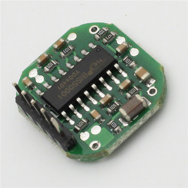
I started playing with the first module listed in my previous post:
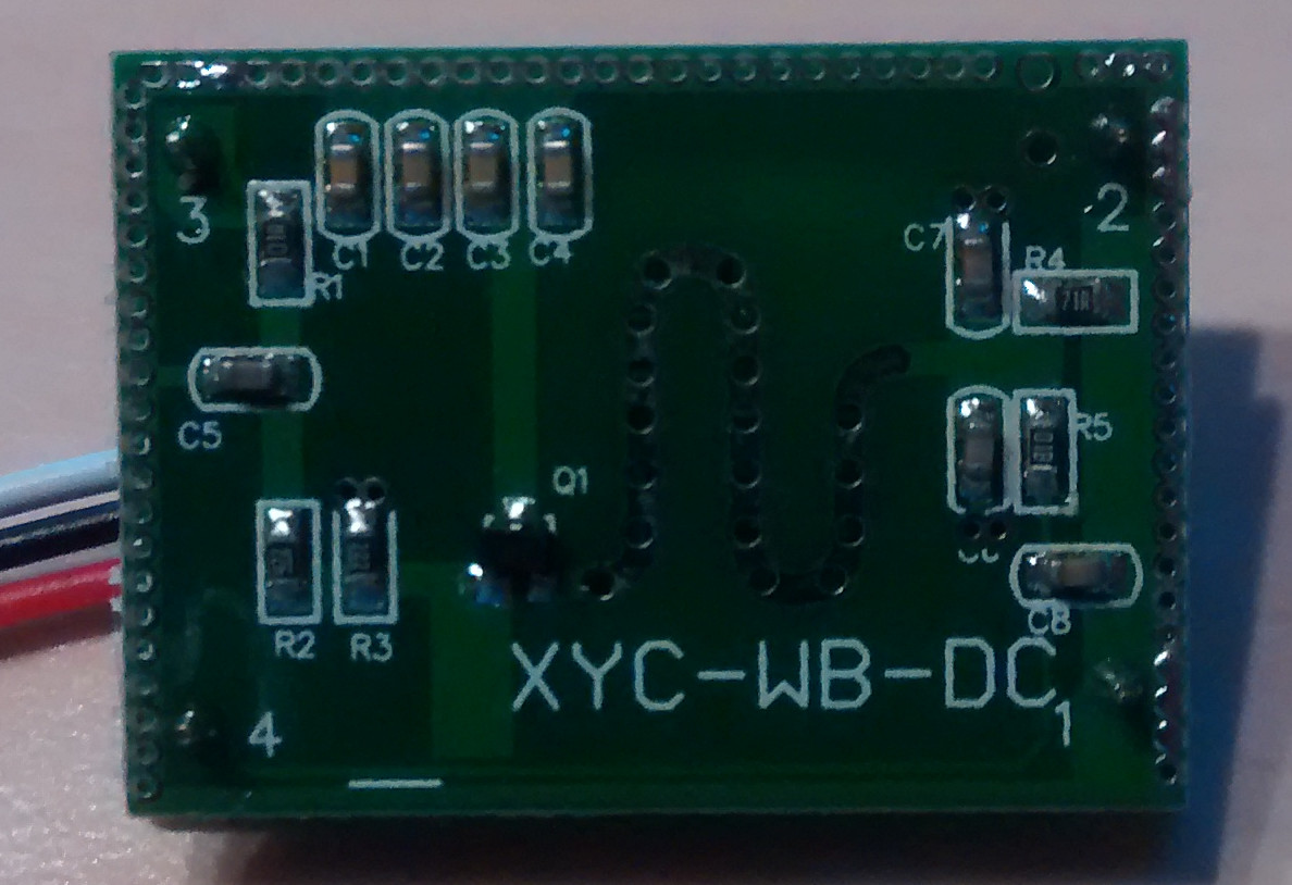
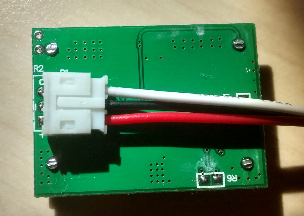
The module is really as easy to connect as a normal pir sensor. There are small text on the pcb. The top most connection (indicated with a 'o') is the sensor output (3,3v for a high and 0v for a low). The middle connection is ground and the bottom connection is Vcc (3,3 to 20v according to the ebay listing).
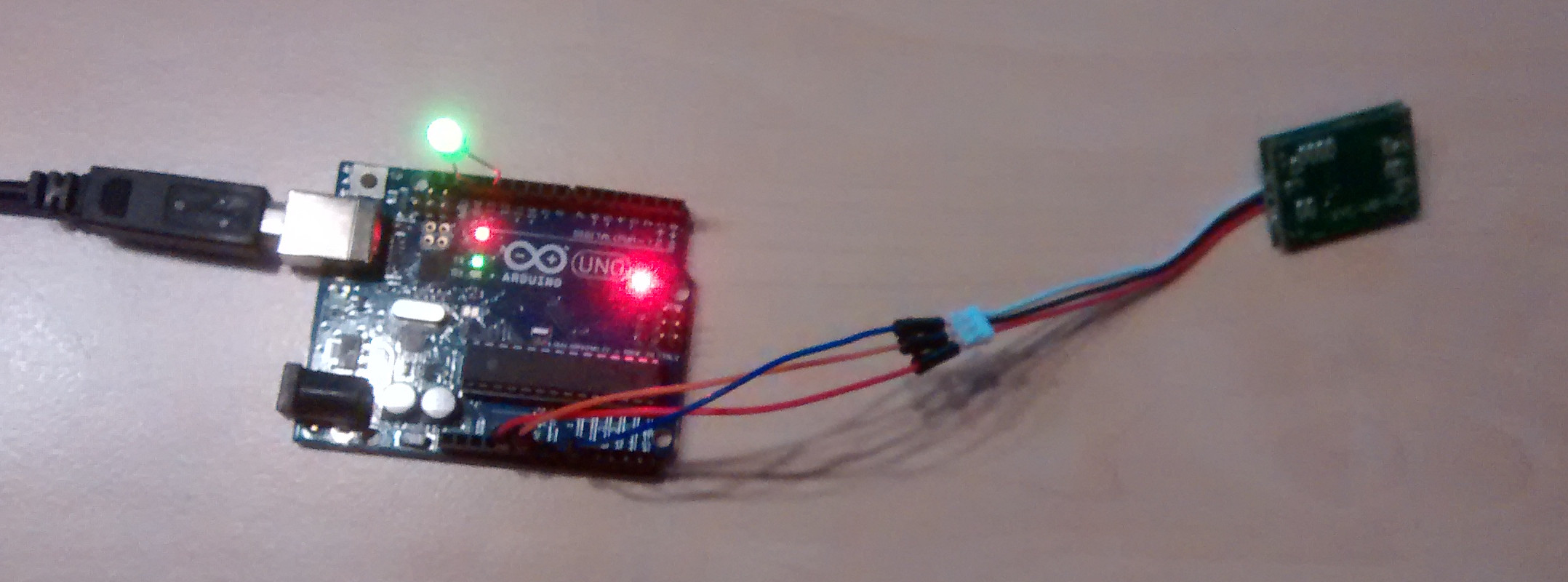
My setup was really simple, just a chinduino powered via usb. The sensor connected to +5v, ground and the output to analog pin A0 (I could have used a digital pin).
The first results are really promising. Some characteristics:
- The sensor is omnidirectional.
- Output is high (3,3V) for 30s when movement is detected
- New movement will restart the 30s timer
- 'low' power consumption. Triggered: 1.5mA; Idle: 1.4mA (measured @5v using a normal multimeter)
- The sensor doesn't react to temperature/light fluctuations (unlike most pir sensors)
Some range tests that triggered the output (note that this is probably not the maximum distance, just the stuff I tested):
- 0-4 meter distance (clear line of sight), moving my arm
- 5-8 meter distance (clear line of sight), walking around
- walking around at 5 meter distance with an indoor brick wall between me and the sensor
Stuff that I still need to test:
- Can the sensitivity be tweaked
- How to change the trigger timer to something else than 30s
- Duration test to see if the module is prone to false positives
-
@danta, this device can detect you when you are in another room ?
@drock1985,
detection delay can be adjusted from 1 second to hundreds of second (two minutes max) by adjusting R6 resistor on the board as explained on this Taobao page (Chinese). By default there’s no resistor and the delay is 30 seconds, and you can adjust the delay by using 1K to 250K resistor. -
@drock1985, Didn't test it yet. I was playing with the other module I bought. Too bad that the other module only seems to work stable from 6V and up (I should have known it, as it was listed on ebay as 7-12v). I was just hoping that it would work at lower voltages. So I will probably stick with the first module for now.
@vil1driver, Yes, detection works through wall and door. I only tested it at a distance of about 5 meter with a brick indoor wall between me and the sensor. I also had to walk around before the sensor picked me up (just lifting my arm wasn't enough).
-
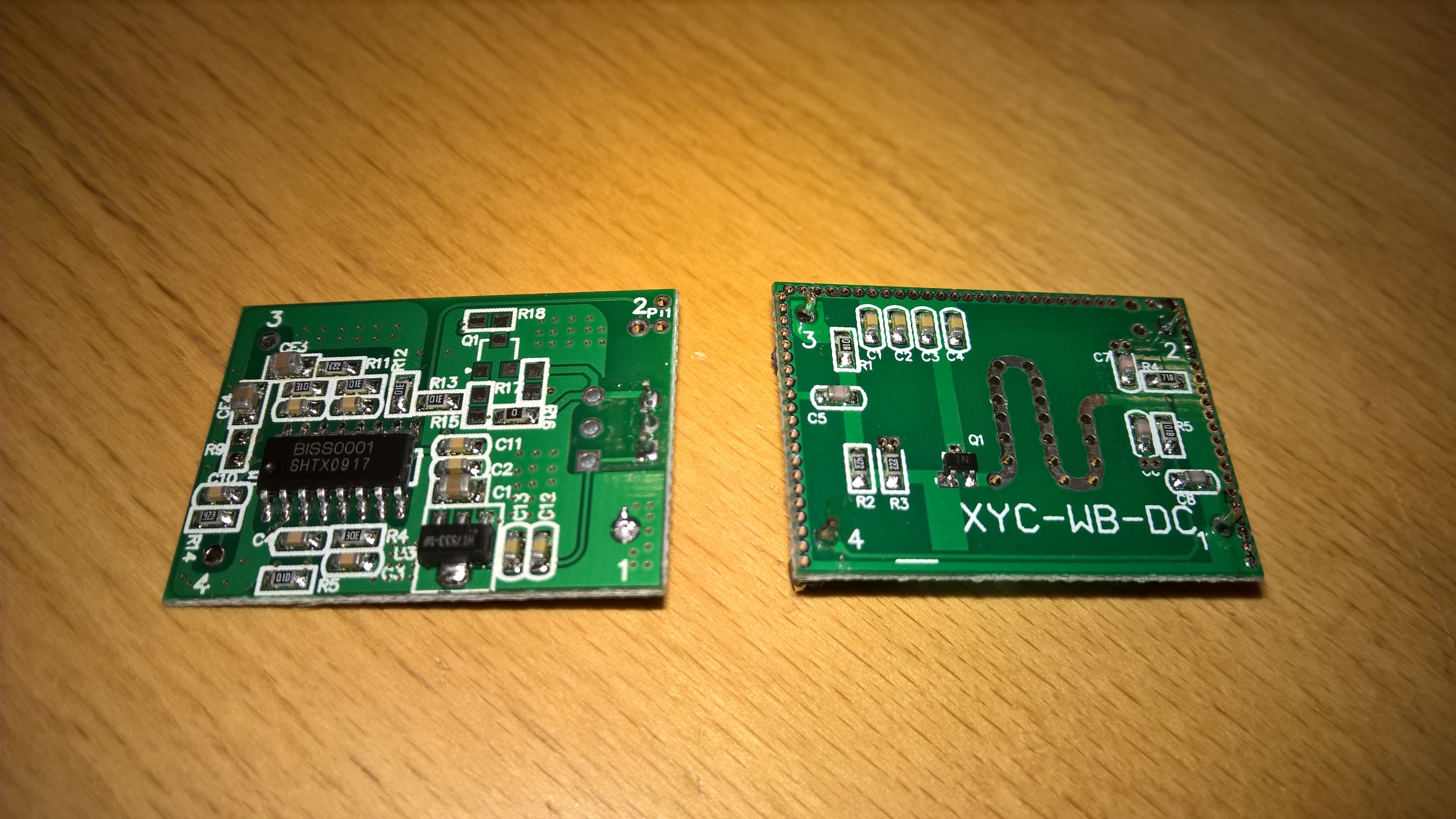
Seems like these modules are using the BISS0001 so it will probably not be possible to run them on a battery node because the BISS has a 3V minimum voltage demand. The current consumption is anyhow also a bit to high for battery application (3mA).
- Tomas
-
Seems like these modules are using the BISS0001 so it will probably not be possible to run them on a battery node because the BISS has a 3V minimum voltage demand. The current consumption is anyhow also a bit to high for battery application (3mA).
I've bought a couple of these and in many ways have been impressed.
My only issue is that I find them far too sensitive (e.g. Detecting movement through wallls)
Has anyone managed to reduce the sensitivity? -
@Luke-Corkill said:
I've bought a couple of these and in many ways have been impressed.
My only issue is that I find them far too sensitive (e.g. Detecting movement through wallls)
Has anyone managed to reduce the sensitivity?To reduce sensitivity workaround - Can you place them high and point them in an angle pointing downwards to ground? will this work?
-
There has been some chat about these modules over on Pete Scargill's site.
Seems that using some aluminium foil you can create a shield so there are at least directional.Here is the thread ( starting at the relevant comment)
http://tech.scargill.net/microwave-radar/#comment-16685
I have not tested this myself yet...
@gregl
Thanks for good link :-)
Yes offcurse I'm so sloooooow we need a proper waveguide or a hornet antenna, so ensure correct directionality ;-)This might not be needed, but a hint what could be done: http://hforsten.com/horn-antenna-for-radar.html
When my doppler radar arrives I will make a trial with a small tinbox I don't know about using alufoil is good for a long periode used outside
http://hackaday.com/2014/02/24/guest-post-try-radar-for-your-next-project/#jp-carousel-115578 -
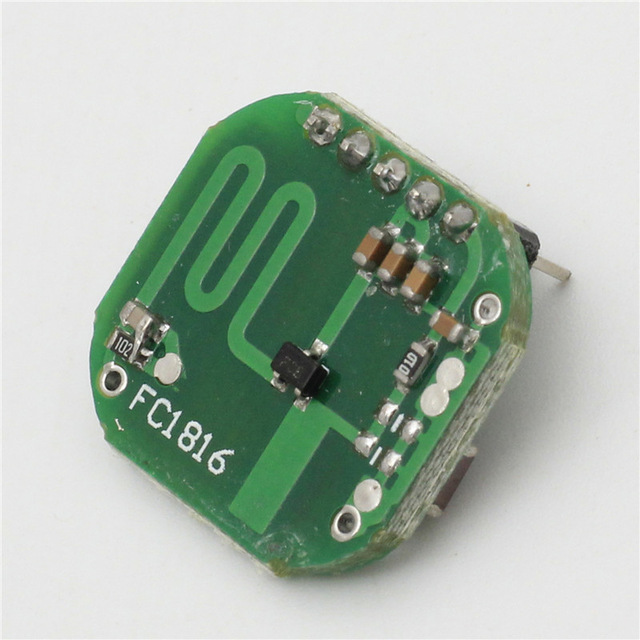
@Yveaux I did some extensive testing on the FC1816 module and I thought I might drop my experience:
http://electronics.stackexchange.com/questions/226031/pinout-of-microwave-motion-sensor-fc1816
In the end I used an 150ohm Series resistor + ~100µF cap behind this to power the FC1816. This eliminated much of the leftover noise. If this is not enough I presented a way to lower the module amplification. In the end I deactivated the biss-trigger output alltogether and grabbed the raw signal. Doing some manual processing:
- take 100 reads
- get the stddev (statistics library)
- high stddev = high fluctuation in values = movement
Take a look at my current working copy of my code for the FC1816:
Some notes:
I power the VCC of the FC1816 from some arduino pins. Thus I can deactivate the microwave sensor at will. This is still not recommended. If you visit the previous link you can see that the BISS has some kind of "warmup"-Period.
I use 3,3Volt to power the NRF24, the arduino and the FC1816 and suffered no strange consequences so far.
Get get some insight about the link quality of the NRF24 I made the function RF24_getObserverTX() accessible from user-space:
MySensors\drivers\RF24\RF24.cpp
uint8_t RF24_getObserveTX(void)
{
	return RF24_readByteRegister(OBSERVE_TX);
}
MySensors\drivers\RF24\RF24.h
uint8_t RF24_getObserveTX(void);The Idea behind the OBSERVE_TX register is that the lower byte presents the number of retrys the NRF24 used in the last send.
The upper 4 bits present the number of total failed packets. I suggest using (0x0F & RF24_getObserveTX()) to get a usable number 0-15 presenting the retry-count. Anything > 0 suggests a packetloss on your link. 15 most likely will mean you ran into an complete fail as the max number of retrys was exhausted.This number might be capped by
// ARD, auto retry count
#define RF24_ARC 15
from the RF24.h driver-file.
TO not run into compiling errors you might need:
http://arduiniana.org/libraries/streaming/
https://github.com/RobTillaart/Arduino/tree/master/libraries/StatisticMicrowaveRadarSensor.ino
#include <Streaming.h>
#include "Statistic.h"


/**
 * The MySensors Arduino library handles the wireless radio link and protocol
 * between your home built sensors/actuators and HA controller of choice.
 * The sensors forms a self healing radio network with optional repeaters. Each
 * repeater and gateway builds a routing tables in EEPROM which keeps track of the
 * network topology allowing messages to be routed to nodes.
 *
 * Created by Henrik Ekblad <henrik.ekblad@mysensors.org>
 * Copyright (C) 2013-2015 Sensnology AB
 * Full contributor list: https://github.com/mysensors/Arduino/graphs/contributors
 *
 * Documentation: http://www.mysensors.org
 * Support Forum: http://forum.mysensors.org
 *
 * This program is free software; you can redistribute it and/or
 * modify it under the terms of the GNU General Public License
 * version 2 as published by the Free Software Foundation.
 *
 *******************************
 *
 * REVISION HISTORY
 * Version 1.0 - Henrik EKblad
 *
 * DESCRIPTION
 * Example sketch showing how to measue light level using a LM393 photo-resistor
 * http://www.mysensors.org/build/light
 */

#define MY_NODE_ID 10
#define MY_BAUD_RATE 57600

// Enable debug prints to serial monitor
//#define MY_DEBUG

// Enable and select radio type attached
#define MY_RADIO_NRF24
//#define MY_RADIO_RFM69

#include <SPI.h>
#include <MySensors.h>

#define LIGHT_SENSOR_ANALOG_PIN A3
#define MICRO_SENSOR_ANALOG_PIN A1

unsigned long SLEEP_TIME = 1000; // Sleep time between reads (in milliseconds)

#define CHILD_ID_LIGHT 0
#define CHILD_ID_MICRO 0
#define TRIPPED_THRESHOLD 50

MyMessage msg_light(CHILD_ID_LIGHT, V_LIGHT_LEVEL); // 23
MyMessage msg_micro(CHILD_ID_MICRO, V_TRIPPED);     // 16
MyMessage msg_micro_debug(0,V_VAR1);   // 24
MyMessage msg_obstx_debug(0,V_VAR2);   // 25

void before()
{
  // LightSensor
  pinMode(A3,INPUT_PULLUP);
  pinMode(A2,OUTPUT);
  digitalWrite(A2,LOW);

  // Microwave
  pinMode(5,OUTPUT);        // VCC BISS0001
  digitalWrite(5,HIGH);

  pinMode(6,OUTPUT);        // Enabled
  digitalWrite(6,LOW);      // Enable

  pinMode(7,OUTPUT);        // GND
  digitalWrite(7,LOW);

  pinMode(8,OUTPUT);        // VCC Radar
  digitalWrite(8,HIGH);

  pinMode(A1,INPUT);        // PIR 2nd Amplification Stage

  // Other
}
void setup()
{

}
void presentation()  {
  // Send the sketch version information to the gateway and Controller
  sendSketchInfo("Microwave+Light", "1.0");

  // Register all sensors to gateway (they will be created as child devices)
  // https://www.mysensors.org/download/serial_api_20#sensor-type
  present(CHILD_ID_LIGHT, S_LIGHT_LEVEL);
  present(CHILD_ID_MICRO, S_MOTION);
  //present(0, S_ARDUINO_NODE);

}

void loop()
{
  // Report VCC
  static long vcc = readVcc();
  static int vccpercent = map(vcc,1800,3280,0,100);
  sendBatteryLevel(max(min(vccpercent,100),0),false);
  Serial << "| vcc: ";
  p(F("%4d"),vcc);
  Serial << " ";
  // Required for ack
  //wait(100);

  // Report LightLevel
  analogRead(LIGHT_SENSOR_ANALOG_PIN);
  int lightLevel_raw = analogRead(LIGHT_SENSOR_ANALOG_PIN);
  int lightLevel = (1023-lightLevel_raw)/10.23; // as of 1023 !!
  Serial << "| light_raw: ";
  p(F("%4d"),lightLevel_raw);
  Serial << " ";
  Serial << "| light: ";
  p(F("%3d"),lightLevel);
  Serial << " ";
  send(msg_light.set(lightLevel),false);

  // Report WirelessLink Information
  Serial << "| observe_tx: ";
  uint8_t obstx = RF24_getObserveTX();
  p(F("%X"),obstx);
  Serial << " ";
  send(msg_obstx_debug.set(0x0F&obstx),false);

  // Report Microwave
  Statistic mw_s;
  mw_s.clear();

  delay(90);
  analogRead(MICRO_SENSOR_ANALOG_PIN);
  delay(10);
  for(int i = 0; i < 1000; i++)
  {
    mw_s.add(analogRead(MICRO_SENSOR_ANALOG_PIN));
    delay(1);
  }
  Serial << "| mw_raw: ";
  int stddev = mw_s.pop_stdev();
  p(F("%4d"),stddev);
  Serial << " ";

  Serial << "| mw_min: ";
  int minimum = mw_s.minimum();
  p(F("%4d"),minimum);
  Serial << " ";

  Serial << "| mw_max: ";
  int maximum = mw_s.maximum();
  p(F("%4d"),maximum);
  Serial << " ";

  Serial << "| mw: " << (stddev > TRIPPED_THRESHOLD ? "1" : "0") << " ";
  send(msg_micro_debug.set(stddev),false);
  while(!send(msg_micro.set(stddev > TRIPPED_THRESHOLD ? "1" : "0"),true))
  {
    wait(10);
  }

  if(isTransportOK())
    wait(100);
  else
    wait(1000);
  Serial << endl;
  //mysleep(500);

}
// https://forum.mysensors.org/topic/3463/m_ack_variable-or-m_set_variable/2
void receive(const MyMessage &message) {
  if (message.isAck()) {
      Serial.print("| GW ack");
      }
}
Helper.ino
long readVcc() { // Read 1.1V reference against AVcc // set the reference to Vcc and the measurement to the internal 1.1V reference #if defined(__AVR_ATmega32U4__) || defined(__AVR_ATmega1280__) || defined(__AVR_ATmega2560__) ADMUX = _BV(REFS0) | _BV(MUX4) | _BV(MUX3) | _BV(MUX2) | _BV(MUX1); #elif defined (__AVR_ATtiny24__) || defined(__AVR_ATtiny44__) || defined(__AVR_ATtiny84__) ADMUX = _BV(MUX5) | _BV(MUX0); #elif defined (__AVR_ATtiny25__) || defined(__AVR_ATtiny45__) || defined(__AVR_ATtiny85__) ADMUX = _BV(MUX3) | _BV(MUX2); #else ADMUX = _BV(REFS0) | _BV(MUX3) | _BV(MUX2) | _BV(MUX1); #endif delay(2); // Wait for Vref to settle ADCSRA |= _BV(ADSC); // Start conversion while (bit_is_set(ADCSRA,ADSC)); // measuring uint8_t low = ADCL; // must read ADCL first - it then locks ADCH uint8_t high = ADCH; // unlocks both long result = (high<<8) | low; result = 1125300L / result; // Calculate Vcc (in mV); 1125300 = 1.1*1023*1000 //result *= 1.0637; return result; // Vcc in millivolts } #include <stdarg.h> void p(const __FlashStringHelper *fmt, ... ){ char buf[128]; // resulting string limited to 128 chars va_list args; va_start (args, fmt); #ifdef __AVR__ vsnprintf_P(buf, sizeof(buf), (const char *)fmt, args); // progmem for AVR #else vsnprintf(buf, sizeof(buf), (const char *)fmt, args); // for the rest of the world #endif va_end(args); Serial.print(buf); } void mysleep(int SLEEP_TIME) { if(isTransportOK()){ Serial << "| wait "; wait(25); Serial << "| zZz > "; sleep(SLEEP_TIME); Serial << "| < zZz " << endl; } else { wait(1000); } } -
@Yveaux I did some extensive testing on the FC1816 module and I thought I might drop my experience:
http://electronics.stackexchange.com/questions/226031/pinout-of-microwave-motion-sensor-fc1816
In the end I used an 150ohm Series resistor + ~100µF cap behind this to power the FC1816. This eliminated much of the leftover noise. If this is not enough I presented a way to lower the module amplification. In the end I deactivated the biss-trigger output alltogether and grabbed the raw signal. Doing some manual processing:
- take 100 reads
- get the stddev (statistics library)
- high stddev = high fluctuation in values = movement
Take a look at my current working copy of my code for the FC1816:
Some notes:
I power the VCC of the FC1816 from some arduino pins. Thus I can deactivate the microwave sensor at will. This is still not recommended. If you visit the previous link you can see that the BISS has some kind of "warmup"-Period.
I use 3,3Volt to power the NRF24, the arduino and the FC1816 and suffered no strange consequences so far.
Get get some insight about the link quality of the NRF24 I made the function RF24_getObserverTX() accessible from user-space:
MySensors\drivers\RF24\RF24.cpp
uint8_t RF24_getObserveTX(void)
{
	return RF24_readByteRegister(OBSERVE_TX);
}
MySensors\drivers\RF24\RF24.h
uint8_t RF24_getObserveTX(void);The Idea behind the OBSERVE_TX register is that the lower byte presents the number of retrys the NRF24 used in the last send.
The upper 4 bits present the number of total failed packets. I suggest using (0x0F & RF24_getObserveTX()) to get a usable number 0-15 presenting the retry-count. Anything > 0 suggests a packetloss on your link. 15 most likely will mean you ran into an complete fail as the max number of retrys was exhausted.This number might be capped by
// ARD, auto retry count
#define RF24_ARC 15
from the RF24.h driver-file.
TO not run into compiling errors you might need:
http://arduiniana.org/libraries/streaming/
https://github.com/RobTillaart/Arduino/tree/master/libraries/StatisticMicrowaveRadarSensor.ino
#include <Streaming.h>
#include "Statistic.h"


/**
 * The MySensors Arduino library handles the wireless radio link and protocol
 * between your home built sensors/actuators and HA controller of choice.
 * The sensors forms a self healing radio network with optional repeaters. Each
 * repeater and gateway builds a routing tables in EEPROM which keeps track of the
 * network topology allowing messages to be routed to nodes.
 *
 * Created by Henrik Ekblad <henrik.ekblad@mysensors.org>
 * Copyright (C) 2013-2015 Sensnology AB
 * Full contributor list: https://github.com/mysensors/Arduino/graphs/contributors
 *
 * Documentation: http://www.mysensors.org
 * Support Forum: http://forum.mysensors.org
 *
 * This program is free software; you can redistribute it and/or
 * modify it under the terms of the GNU General Public License
 * version 2 as published by the Free Software Foundation.
 *
 *******************************
 *
 * REVISION HISTORY
 * Version 1.0 - Henrik EKblad
 *
 * DESCRIPTION
 * Example sketch showing how to measue light level using a LM393 photo-resistor
 * http://www.mysensors.org/build/light
 */

#define MY_NODE_ID 10
#define MY_BAUD_RATE 57600

// Enable debug prints to serial monitor
//#define MY_DEBUG

// Enable and select radio type attached
#define MY_RADIO_NRF24
//#define MY_RADIO_RFM69

#include <SPI.h>
#include <MySensors.h>

#define LIGHT_SENSOR_ANALOG_PIN A3
#define MICRO_SENSOR_ANALOG_PIN A1

unsigned long SLEEP_TIME = 1000; // Sleep time between reads (in milliseconds)

#define CHILD_ID_LIGHT 0
#define CHILD_ID_MICRO 0
#define TRIPPED_THRESHOLD 50

MyMessage msg_light(CHILD_ID_LIGHT, V_LIGHT_LEVEL); // 23
MyMessage msg_micro(CHILD_ID_MICRO, V_TRIPPED);     // 16
MyMessage msg_micro_debug(0,V_VAR1);   // 24
MyMessage msg_obstx_debug(0,V_VAR2);   // 25

void before()
{
  // LightSensor
  pinMode(A3,INPUT_PULLUP);
  pinMode(A2,OUTPUT);
  digitalWrite(A2,LOW);

  // Microwave
  pinMode(5,OUTPUT);        // VCC BISS0001
  digitalWrite(5,HIGH);

  pinMode(6,OUTPUT);        // Enabled
  digitalWrite(6,LOW);      // Enable

  pinMode(7,OUTPUT);        // GND
  digitalWrite(7,LOW);

  pinMode(8,OUTPUT);        // VCC Radar
  digitalWrite(8,HIGH);

  pinMode(A1,INPUT);        // PIR 2nd Amplification Stage

  // Other
}
void setup()
{

}
void presentation()  {
  // Send the sketch version information to the gateway and Controller
  sendSketchInfo("Microwave+Light", "1.0");

  // Register all sensors to gateway (they will be created as child devices)
  // https://www.mysensors.org/download/serial_api_20#sensor-type
  present(CHILD_ID_LIGHT, S_LIGHT_LEVEL);
  present(CHILD_ID_MICRO, S_MOTION);
  //present(0, S_ARDUINO_NODE);

}

void loop()
{
  // Report VCC
  static long vcc = readVcc();
  static int vccpercent = map(vcc,1800,3280,0,100);
  sendBatteryLevel(max(min(vccpercent,100),0),false);
  Serial << "| vcc: ";
  p(F("%4d"),vcc);
  Serial << " ";
  // Required for ack
  //wait(100);

  // Report LightLevel
  analogRead(LIGHT_SENSOR_ANALOG_PIN);
  int lightLevel_raw = analogRead(LIGHT_SENSOR_ANALOG_PIN);
  int lightLevel = (1023-lightLevel_raw)/10.23; // as of 1023 !!
  Serial << "| light_raw: ";
  p(F("%4d"),lightLevel_raw);
  Serial << " ";
  Serial << "| light: ";
  p(F("%3d"),lightLevel);
  Serial << " ";
  send(msg_light.set(lightLevel),false);

  // Report WirelessLink Information
  Serial << "| observe_tx: ";
  uint8_t obstx = RF24_getObserveTX();
  p(F("%X"),obstx);
  Serial << " ";
  send(msg_obstx_debug.set(0x0F&obstx),false);

  // Report Microwave
  Statistic mw_s;
  mw_s.clear();

  delay(90);
  analogRead(MICRO_SENSOR_ANALOG_PIN);
  delay(10);
  for(int i = 0; i < 1000; i++)
  {
    mw_s.add(analogRead(MICRO_SENSOR_ANALOG_PIN));
    delay(1);
  }
  Serial << "| mw_raw: ";
  int stddev = mw_s.pop_stdev();
  p(F("%4d"),stddev);
  Serial << " ";

  Serial << "| mw_min: ";
  int minimum = mw_s.minimum();
  p(F("%4d"),minimum);
  Serial << " ";

  Serial << "| mw_max: ";
  int maximum = mw_s.maximum();
  p(F("%4d"),maximum);
  Serial << " ";

  Serial << "| mw: " << (stddev > TRIPPED_THRESHOLD ? "1" : "0") << " ";
  send(msg_micro_debug.set(stddev),false);
  while(!send(msg_micro.set(stddev > TRIPPED_THRESHOLD ? "1" : "0"),true))
  {
    wait(10);
  }

  if(isTransportOK())
    wait(100);
  else
    wait(1000);
  Serial << endl;
  //mysleep(500);

}
// https://forum.mysensors.org/topic/3463/m_ack_variable-or-m_set_variable/2
void receive(const MyMessage &message) {
  if (message.isAck()) {
      Serial.print("| GW ack");
      }
}
Helper.ino
long readVcc() { // Read 1.1V reference against AVcc // set the reference to Vcc and the measurement to the internal 1.1V reference #if defined(__AVR_ATmega32U4__) || defined(__AVR_ATmega1280__) || defined(__AVR_ATmega2560__) ADMUX = _BV(REFS0) | _BV(MUX4) | _BV(MUX3) | _BV(MUX2) | _BV(MUX1); #elif defined (__AVR_ATtiny24__) || defined(__AVR_ATtiny44__) || defined(__AVR_ATtiny84__) ADMUX = _BV(MUX5) | _BV(MUX0); #elif defined (__AVR_ATtiny25__) || defined(__AVR_ATtiny45__) || defined(__AVR_ATtiny85__) ADMUX = _BV(MUX3) | _BV(MUX2); #else ADMUX = _BV(REFS0) | _BV(MUX3) | _BV(MUX2) | _BV(MUX1); #endif delay(2); // Wait for Vref to settle ADCSRA |= _BV(ADSC); // Start conversion while (bit_is_set(ADCSRA,ADSC)); // measuring uint8_t low = ADCL; // must read ADCL first - it then locks ADCH uint8_t high = ADCH; // unlocks both long result = (high<<8) | low; result = 1125300L / result; // Calculate Vcc (in mV); 1125300 = 1.1*1023*1000 //result *= 1.0637; return result; // Vcc in millivolts } #include <stdarg.h> void p(const __FlashStringHelper *fmt, ... ){ char buf[128]; // resulting string limited to 128 chars va_list args; va_start (args, fmt); #ifdef __AVR__ vsnprintf_P(buf, sizeof(buf), (const char *)fmt, args); // progmem for AVR #else vsnprintf(buf, sizeof(buf), (const char *)fmt, args); // for the rest of the world #endif va_end(args); Serial.print(buf); } void mysleep(int SLEEP_TIME) { if(isTransportOK()){ Serial << "| wait "; wait(25); Serial << "| zZz > "; sleep(SLEEP_TIME); Serial << "| < zZz " << endl; } else { wait(1000); } }@cimba007 wow, you did some serious research there! (I see you make good use of the arduino plot function)
I'll certainly come back to your research once I start with this sensor (so much to choose from...)
Any ideas about current consumption? Is this a viable alternative to battery powered pir sensors?http://yveaux.blogspot.nl
-
@cimba007 wow, you did some serious research there! (I see you make good use of the arduino plot function)
I'll certainly come back to your research once I start with this sensor (so much to choose from...)
Any ideas about current consumption? Is this a viable alternative to battery powered pir sensors?@Yveaux From my oppinion the radar modules are not suited for battery usage. Their drain something like 3-5mA and are not easy to put to sleep. Remember the warm-up period of the BISS. It seems to be like 10-15seconds.
The plots are from another sketch, not the one I posted but using them is pretty straight forward.
In my sketch have a look at these parts:
  Serial << "| mw_min: ";
  int minimum = mw_s.minimum();
  p(F("%4d"),minimum);
  Serial << " ";
To use the arduino plotting all you ahve to do is send a string like this:
0,10,534,123 .. whatever .. beware that no other serial output should happen if you want to use the arduino build-in plotting. Using the streaming library ( http://arduiniana.org/libraries/streaming/ ) it all boils down to a single line:
Serial << mw_s.minimum() << "," << mw_s.maximum() << "," << mw_s.pop_stdev() << endl;In addition to the power consumption my approach requires sampling the analog input for a whole second .. or the more the better.
This might be improved if you can prevent the FC1816 from retriggering itself. I had some serious problems as during the "inhibitor" period the analogOutput from the 2nd amplification stage was quite high often instantly retrigger the biss-output after the inhibition period ended.
One solution might be this:
Try this if you want to look down this approch:
- Power the FC1816 VCC and UDP through an RC-Section (100Ohm Resistor and after that (on the side of the FC1816) an capacitory ~100-220µF)
- Replace amplification resistor from 105 to eg. 154 (lowering the amplification)
To find the best value I used an variable resistor parallel to the 105-Ohms SMD-Resistor
But .. don't forget the benefits of *he microwave sensor. You can mount it straight to a door and it would detect persons in front of the door without them noticing. For this reason I try to build an "Alarm-node" that can be hidden inside the house. Later I might improve the FC1816 with some aluminium foil for shielding as suggested earlier.
I would suggest using an PIR if you need a battery powered node. Have a look at ( http://kavacky.lv/bypassing-sen-08630-pir-motion-sensors-voltage-regulator-to-work-with-3-3-v ). Some PIRs have a Regulator which might not be suited if you are running on battery using 3,3Volt.
-
@Yveaux From my oppinion the radar modules are not suited for battery usage. Their drain something like 3-5mA and are not easy to put to sleep. Remember the warm-up period of the BISS. It seems to be like 10-15seconds.
The plots are from another sketch, not the one I posted but using them is pretty straight forward.
In my sketch have a look at these parts:
  Serial << "| mw_min: ";
  int minimum = mw_s.minimum();
  p(F("%4d"),minimum);
  Serial << " ";
To use the arduino plotting all you ahve to do is send a string like this:
0,10,534,123 .. whatever .. beware that no other serial output should happen if you want to use the arduino build-in plotting. Using the streaming library ( http://arduiniana.org/libraries/streaming/ ) it all boils down to a single line:
Serial << mw_s.minimum() << "," << mw_s.maximum() << "," << mw_s.pop_stdev() << endl;In addition to the power consumption my approach requires sampling the analog input for a whole second .. or the more the better.
This might be improved if you can prevent the FC1816 from retriggering itself. I had some serious problems as during the "inhibitor" period the analogOutput from the 2nd amplification stage was quite high often instantly retrigger the biss-output after the inhibition period ended.
One solution might be this:
Try this if you want to look down this approch:
- Power the FC1816 VCC and UDP through an RC-Section (100Ohm Resistor and after that (on the side of the FC1816) an capacitory ~100-220µF)
- Replace amplification resistor from 105 to eg. 154 (lowering the amplification)
To find the best value I used an variable resistor parallel to the 105-Ohms SMD-Resistor
But .. don't forget the benefits of *he microwave sensor. You can mount it straight to a door and it would detect persons in front of the door without them noticing. For this reason I try to build an "Alarm-node" that can be hidden inside the house. Later I might improve the FC1816 with some aluminium foil for shielding as suggested earlier.
I would suggest using an PIR if you need a battery powered node. Have a look at ( http://kavacky.lv/bypassing-sen-08630-pir-motion-sensors-voltage-regulator-to-work-with-3-3-v ). Some PIRs have a Regulator which might not be suited if you are running on battery using 3,3Volt.
-
All things from my previous post regarding the wiring are still needed:
Here is a stripped down example on how to use the FC1816 Microwave Sensor. You need the following library:
https://github.com/RobTillaart/Arduino/tree/master/libraries/Statistic
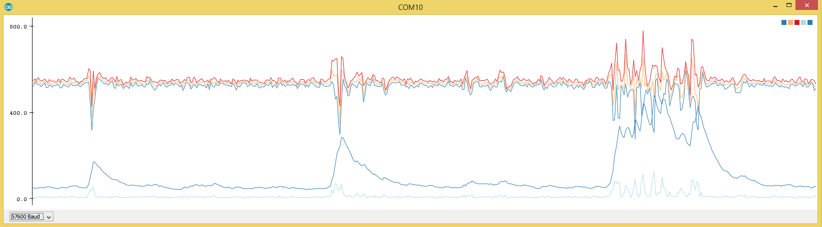
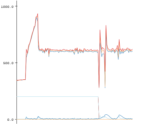
#include "Statistic.h"

#define MICRO_SENSOR_ANALOG_PIN A1

void setup()
{

  Serial.begin(57600);
  Serial.print("begin");

  // Microwave
  pinMode(5,OUTPUT);        // VCC BISS0001
  digitalWrite(5,HIGH);

  pinMode(6,OUTPUT);        // Enabled
  digitalWrite(6,LOW);      // DISABLE PLEASE!

  pinMode(7,OUTPUT);        // GND
  digitalWrite(7,LOW);

  pinMode(A1,INPUT);        // PIR 2nd amplification stage

  pinMode(A0,OUTPUT);       // UPD microwave generator
  digitalWrite(A0,HIGH);

}

void loop()
{
  // Report Microwave
  static Statistic mw_s;
  static uint16_t stdev_sum = 0;
  //mw_s.clear();

  //digitalWrite(8,HIGH);
  //delay(100);
  analogRead(MICRO_SENSOR_ANALOG_PIN);
  uint16_t reading;
  for(int i = 0; i < 200; i++)
  {
    reading = analogRead(MICRO_SENSOR_ANALOG_PIN);
    mw_s.add(reading);
    //Serial.println(reading);
    //Serial.flush();
    //delay(50);
    //LowPower.powerDown(SLEEP_60MS, ADC_ON, BOD_OFF);
    //delay(1);
  }
  Serial.print(mw_s.minimum());   Serial.print(",");
  Serial.print(mw_s.average());   Serial.print(",");
  Serial.print(mw_s.maximum());   Serial.print(",");
  Serial.print(mw_s.pop_stdev()); Serial.print(",");
  stdev_sum += mw_s.pop_stdev();
  Serial.print(stdev_sum); //Serial.print(",");
  Serial.println();
  stdev_sum *= 0.9;
  mw_s.clear();
}
I just had the idea to sum up the std-dev and decrease it by 10% every round. Thus the code is less prone to peaks.
stdev_sum is the lower dark blue line which can now be much easier compared to a threshold.
Some measurement with my µCurrent-Gold:
Unmodified code as above, power LED removed from ProMini @ 8Mhz internal osci with LDO desoldered
4,8mAI tried to put the FC1816 into sleep by disable the power to the Microwave generator but this doesn't work.
I modified the fuses for 8Mhz with 0ms wakeup delay for stabelizing the oscillator. No risk no phun ;-)The most practical solution I got to replace a PIR (still nothing as close as a PIR ;-ö)
1530µA
with this code:
Note that the radar generator just can't be disable as it needs 10-15seconds to stabelize after power up
#include <LowPower.h> #include "Statistic.h" #define MICRO_SENSOR_ANALOG_PIN A1 void setup() { Serial.begin(57600); Serial.print("begin"); // Microwave pinMode(5,OUTPUT); // VCC BISS0001 digitalWrite(5,HIGH); pinMode(6,OUTPUT); // Enabled digitalWrite(6,LOW); // DISABLE PLEASE! pinMode(7,OUTPUT); // GND digitalWrite(7,LOW); pinMode(A1,INPUT); // PIR 2nd amplification stage pinMode(A0,OUTPUT); // UPD microwave generator digitalWrite(A0,HIGH); } void loop() { // Report Microwave static Statistic mw_s; static uint16_t stdev_sum = 0; //mw_s.clear(); //delay(100); analogRead(MICRO_SENSOR_ANALOG_PIN); uint16_t reading; for(int i = 0; i < 10; i++) { LowPower.powerDown(SLEEP_15Ms, ADC_ON, BOD_OFF); reading = analogRead(MICRO_SENSOR_ANALOG_PIN); mw_s.add(reading); //Serial.println(reading); //Serial.flush(); //delay(50); LowPower.powerDown(SLEEP_15Ms, ADC_ON, BOD_OFF); //delay(1); } Serial.print(mw_s.minimum()); Serial.print(","); Serial.print(mw_s.average()); Serial.print(","); Serial.print(mw_s.maximum()); Serial.print(","); Serial.print(mw_s.pop_stdev()); Serial.print(","); stdev_sum += mw_s.pop_stdev(); Serial.print(stdev_sum); //Serial.print(","); Serial.println(); Serial.flush(); stdev_sum *= 0.9; mw_s.clear(); } -
All things from my previous post regarding the wiring are still needed:
Here is a stripped down example on how to use the FC1816 Microwave Sensor. You need the following library:
https://github.com/RobTillaart/Arduino/tree/master/libraries/Statistic
#include "Statistic.h"

#define MICRO_SENSOR_ANALOG_PIN A1

void setup()
{

  Serial.begin(57600);
  Serial.print("begin");

  // Microwave
  pinMode(5,OUTPUT);        // VCC BISS0001
  digitalWrite(5,HIGH);

  pinMode(6,OUTPUT);        // Enabled
  digitalWrite(6,LOW);      // DISABLE PLEASE!

  pinMode(7,OUTPUT);        // GND
  digitalWrite(7,LOW);

  pinMode(A1,INPUT);        // PIR 2nd amplification stage

  pinMode(A0,OUTPUT);       // UPD microwave generator
  digitalWrite(A0,HIGH);

}

void loop()
{
  // Report Microwave
  static Statistic mw_s;
  static uint16_t stdev_sum = 0;
  //mw_s.clear();

  //digitalWrite(8,HIGH);
  //delay(100);
  analogRead(MICRO_SENSOR_ANALOG_PIN);
  uint16_t reading;
  for(int i = 0; i < 200; i++)
  {
    reading = analogRead(MICRO_SENSOR_ANALOG_PIN);
    mw_s.add(reading);
    //Serial.println(reading);
    //Serial.flush();
    //delay(50);
    //LowPower.powerDown(SLEEP_60MS, ADC_ON, BOD_OFF);
    //delay(1);
  }
  Serial.print(mw_s.minimum());   Serial.print(",");
  Serial.print(mw_s.average());   Serial.print(",");
  Serial.print(mw_s.maximum());   Serial.print(",");
  Serial.print(mw_s.pop_stdev()); Serial.print(",");
  stdev_sum += mw_s.pop_stdev();
  Serial.print(stdev_sum); //Serial.print(",");
  Serial.println();
  stdev_sum *= 0.9;
  mw_s.clear();
}
I just had the idea to sum up the std-dev and decrease it by 10% every round. Thus the code is less prone to peaks.
stdev_sum is the lower dark blue line which can now be much easier compared to a threshold.
Some measurement with my µCurrent-Gold:
Unmodified code as above, power LED removed from ProMini @ 8Mhz internal osci with LDO desoldered
4,8mAI tried to put the FC1816 into sleep by disable the power to the Microwave generator but this doesn't work.
I modified the fuses for 8Mhz with 0ms wakeup delay for stabelizing the oscillator. No risk no phun ;-)The most practical solution I got to replace a PIR (still nothing as close as a PIR ;-ö)
1530µA
with this code:
Note that the radar generator just can't be disable as it needs 10-15seconds to stabelize after power up
#include <LowPower.h> #include "Statistic.h" #define MICRO_SENSOR_ANALOG_PIN A1 void setup() { Serial.begin(57600); Serial.print("begin"); // Microwave pinMode(5,OUTPUT); // VCC BISS0001 digitalWrite(5,HIGH); pinMode(6,OUTPUT); // Enabled digitalWrite(6,LOW); // DISABLE PLEASE! pinMode(7,OUTPUT); // GND digitalWrite(7,LOW); pinMode(A1,INPUT); // PIR 2nd amplification stage pinMode(A0,OUTPUT); // UPD microwave generator digitalWrite(A0,HIGH); } void loop() { // Report Microwave static Statistic mw_s; static uint16_t stdev_sum = 0; //mw_s.clear(); //delay(100); analogRead(MICRO_SENSOR_ANALOG_PIN); uint16_t reading; for(int i = 0; i < 10; i++) { LowPower.powerDown(SLEEP_15Ms, ADC_ON, BOD_OFF); reading = analogRead(MICRO_SENSOR_ANALOG_PIN); mw_s.add(reading); //Serial.println(reading); //Serial.flush(); //delay(50); LowPower.powerDown(SLEEP_15Ms, ADC_ON, BOD_OFF); //delay(1); } Serial.print(mw_s.minimum()); Serial.print(","); Serial.print(mw_s.average()); Serial.print(","); Serial.print(mw_s.maximum()); Serial.print(","); Serial.print(mw_s.pop_stdev()); Serial.print(","); stdev_sum += mw_s.pop_stdev(); Serial.print(stdev_sum); //Serial.print(","); Serial.println(); Serial.flush(); stdev_sum *= 0.9; mw_s.clear(); } -
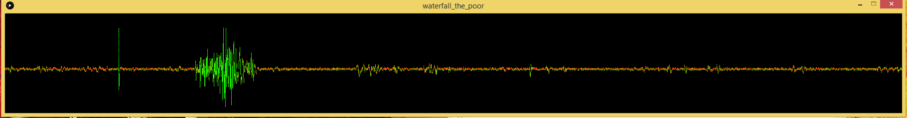
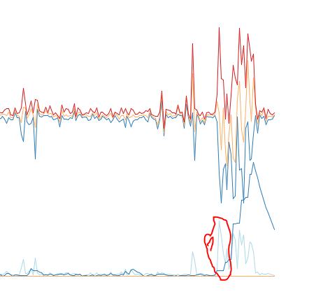
After a few more days of testing I noticed these ugly "PEAKS" from my FC1816 readings. I added lots of capacitors and RC and LC sections but still .. nasty little peaks (left side in the beginning)
In my previous post replace this line:
stdev_sum += mw_s.pop_stdev();with this:
  // Ignore the first 3 peaks within short succession
  // Real movement should mean there are more peaks/activity over a long time
  static uint8_t peakcount = 0;
  if(mw_s.pop_stdev() > 30 && peakcount < 3)
  {
    peakcount++;
  }
  else
  {
    stdev_sum += mw_s.pop_stdev();
    stdev_sum *= 0.92; //
    if (stdev_sum >= 7)
      stdev_sum -= 7; // Default background noise
    if (stdev_sum > 512)
      stdev_sum = 512;

    if(peakcount > 0)
      peakcount--;
  }
With this code the first 3 peaks are essentially removed .. if there is really some movement it should last for a few seconds and would still be detected.
I have invested like 10-20hours into testing and debugging the FC1816 and I can say .. this thing is .. peculiar ..
I hate it cause of the spikes, the amplification which has to be manually altered with a pot .. but at the same time I love it ..
I can detect my foot beckoning 2-3meters apart in my bed :D
An example of the code snipped in action:
Here you can see the big spikes in the beginning completely ignored (1)
-
Currently I don't plan to make a library .. a library implies that the sensor is very easy to use .. plug in + import library.
The FC1816 is not such a sensor.
- Needs Voltage-Supply filter (RC Section)
- Need separate cable to grab the signal at the 2nd amplification stage
- Need potentiometer to lower the amplification
- Is very prone to random noise (in fact even entering RF24 or ATMEGA328 low power mode might increase noise floor a lot)
Using a "simple to use" library and not getting the expected result of an "easy"-sensor would be very disappointing. For now I would say this is an advanced sensor with some pitfalls.
I update this thread with my findings to hopefully make everybodys life a bit easyer if you want to tinker with the FC1816 although you now know it is a little beast ;-)
If you need any help just ask here and I will support you the best I can.
Hello! It looks like you're interested in this conversation, but you don't have an account yet.
Getting fed up of having to scroll through the same posts each visit? When you register for an account, you'll always come back to exactly where you were before, and choose to be notified of new replies (either via email, or push notification). You'll also be able to save bookmarks and upvote posts to show your appreciation to other community members.
With your input, this post could be even better 💗
Register Login