Skip to content
  • MySensors
  • OpenHardware.io
  • Categories
  • Recent
  • Tags
  • Popular
Skins
  • Light
  • Brite
  • Cerulean
  • Cosmo
  • Flatly
  • Journal
  • Litera
  • Lumen
  • Lux
  • Materia
  • Minty
  • Morph
  • Pulse
  • Sandstone
  • Simplex
  • Sketchy
  • Spacelab
  • United
  • Yeti
  • Zephyr
  • Dark
  • Cyborg
  • Darkly
  • Quartz
  • Slate
  • Solar
  • Superhero
  • Vapor

  • Default (No Skin)
  • No Skin
Collapse
Brand Logo
  1. Home
  2. Development
  3. [Tutorial] How to burn 1Mhz & 8Mhz bootloader using Arduino IDE 1.6.5-r5

[Tutorial] How to burn 1Mhz & 8Mhz bootloader using Arduino IDE 1.6.5-r5

Scheduled Pinned Locked Moved Development
86 Posts 20 Posters 102.6k Views 28 Watching
  • Oldest to Newest
  • Newest to Oldest
  • Most Votes
Reply
  • Reply as topic
Log in to reply
This topic has been deleted. Only users with topic management privileges can see it.
  • GertSandersG GertSanders

    @jacikaas
    So only disconnect the white cable but leave the black one in the breadboard.

    J Offline
    J Offline
    jacikaas
    wrote on last edited by
    #53

    @GertSanders

    Thank You!!! That was very silly failure, which eats a lot of time... But it breaks the ice :)))

    Thank You a lot @GertSanders !

    1 Reply Last reply
    0
    • siodS Offline
      siodS Offline
      siod
      wrote on last edited by
      #54

      Hi guys,

      I flashed a few sensors already using the 8 MHz and 1MHz bootloaders. I would like to know if I could update my nodes OTA or would I have to modify sth. to make it possible?

      still learning...

      GertSandersG 1 Reply Last reply
      0
      • siodS siod

        Hi guys,

        I flashed a few sensors already using the 8 MHz and 1MHz bootloaders. I would like to know if I could update my nodes OTA or would I have to modify sth. to make it possible?

        GertSandersG Offline
        GertSandersG Offline
        GertSanders
        Hardware Contributor
        wrote on last edited by
        #55

        @siod
        For OTA you need to flash the boot loaders that allow this. The standard boot loaders do not have this ability to OTA update.

        siodS 1 Reply Last reply
        0
        • F Offline
          F Offline
          flopp
          wrote on last edited by
          #56

          I am also having problem upload with FTDI, I can upload sketch if I use UNO as ISP.
          I read that someone also have problem above but nothing is helping me.
          I am using Arduino IDE 1.6.8.
          Can it be the version of Arduino IDE?

          dpressleD 1 Reply Last reply
          0
          • F flopp

            I am also having problem upload with FTDI, I can upload sketch if I use UNO as ISP.
            I read that someone also have problem above but nothing is helping me.
            I am using Arduino IDE 1.6.8.
            Can it be the version of Arduino IDE?

            dpressleD Offline
            dpressleD Offline
            dpressle
            wrote on last edited by
            #57

            @flopp The only way i was able to upload with ftdi is to connect RTS pin to pin 1 via a 0.1 uf cap

            F 1 Reply Last reply
            0
            • dpressleD dpressle

              @flopp The only way i was able to upload with ftdi is to connect RTS pin to pin 1 via a 0.1 uf cap

              F Offline
              F Offline
              flopp
              wrote on last edited by flopp
              #58

              @dpressle
              OK will try. Cap minus to GND and cap positive to RTS?

              EDIT: I am using 1Mhz setup
              I change the LOW fuse and Extended but what I can see is that my changes only changes the BOD and internal oscillator.

              low_fuses=0x42
              extended_fuses=0x06

              I noticed that my board have high_fuses=0xde, this setting the 1MHz board also have but not 8MHz. This mean that I dont have any space for Bootloader, can this be my problem?

              GertSandersG 1 Reply Last reply
              0
              • F Offline
                F Offline
                flopp
                wrote on last edited by
                #59

                I tried with above 8MHz setting and then I can upload to ATmega with a FTDI.

                I will try to change settings one-by-one until I cant upload and write back here.

                1 Reply Last reply
                1
                • F Offline
                  F Offline
                  flopp
                  wrote on last edited by flopp
                  #60

                  With this board.txt config

                  atmega328bb.name=ATmega328 on a breadboard (8 MHz internal clock)
                  
                  atmega328bb.upload.protocol=arduino
                  atmega328bb.upload.maximum_size=30720
                  atmega328bb.upload.speed=57600
                  atmega328bb.bootloader.low_fuses=0xE2
                  atmega328bb.bootloader.high_fuses=0xDA
                  atmega328bb.bootloader.extended_fuses=0x06
                  atmega328bb.bootloader.file=atmega/ATmegaBOOT_168_atmega328_pro_8MHz.hex
                  atmega328bb.bootloader.unlock_bits=0x3F
                  atmega328bb.bootloader.lock_bits=0x0F
                  atmega328bb.build.mcu=atmega328p
                  atmega328bb.build.f_cpu=8000000L
                  atmega328bb.build.core=arduino:arduino
                  atmega328bb.build.variant=arduino:standard
                  atmega328bb.bootloader.tool=arduino:avrdude
                  atmega328bb.upload.tool=arduino:avrdude
                  

                  I can upload with FTDI. When Arduino IDE change from "Compiling sketch" to "Upload", disconnect DTR and it work.
                  With my sketch it was using 12,9 uA when sleep
                  Same result if I change f_cpu to 1000000L

                  F 1 Reply Last reply
                  0
                  • F Offline
                    F Offline
                    flopp
                    wrote on last edited by
                    #61

                    Today I could upload without removing DTR :)

                    1 Reply Last reply
                    0
                    • GertSandersG GertSanders

                      @siod
                      For OTA you need to flash the boot loaders that allow this. The standard boot loaders do not have this ability to OTA update.

                      siodS Offline
                      siodS Offline
                      siod
                      wrote on last edited by
                      #62

                      @GertSanders said:

                      @siod
                      For OTA you need to flash the boot loaders that allow this. The standard boot loaders do not have this ability to OTA update.

                      Ok, but after the new release of mysensors ver 2.0 lib and my wish to update my gw and sensor nodes I would like to add OTA update ability as well for upcoming updates.

                      • So does a 1 MHz Bootloader with OTA exist that is compatible to the one from above?
                      • Could OTA easily be added to the above 1MHz Bootloader?
                      • Should i just use the "ATmega328 internal 8Mhz with MYSBootloader" instead of the above mentioned bootloaders?

                      still learning...

                      1 Reply Last reply
                      0
                      • cimba007C Offline
                        cimba007C Offline
                        cimba007
                        wrote on last edited by
                        #63

                        Recently I read a lot about the 0ms, 4.1ms, 65ms start-up time of the low fuses.

                        I thought adding a small example to prove that the 65ms start-up time is apparently only important during initial powerup.

                        Used library: https://github.com/rocketscream/Low-Power

                        Testcode:

                        #include <LowPower.h>
                        
                        // the setup function runs once when you press reset or power the board
                        void setup() {
                          // initialize digital pin 13 as an output.
                          pinMode(13, OUTPUT);
                          Serial.begin(19200);
                        }
                        
                        // the loop function runs over and over again forever
                        void loop() {
                        
                          LowPower.powerDown(SLEEP_15Ms, ADC_OFF, BOD_OFF);  
                          Serial.write(".");
                          Serial.flush();
                        }
                        

                        First dot:
                        0_1472662964196_upload-072d9398-ce73-4662-bbed-0e2c10ba1cee

                        Second dot:
                        0_1472663028575_upload-c7a0d030-d518-469e-a077-83f755199ab0

                        = 15ms (sleep) + 2ms (serial communication)
                        ~17ms including overhead for sending serial command

                        I will try out your bootloader and I can only say that it looks promising

                        1 Reply Last reply
                        0
                        • cimba007C Offline
                          cimba007C Offline
                          cimba007
                          wrote on last edited by cimba007
                          #64

                          I ran into an rather strange problem.

                          Mygateway is using esp8266_mqtt_client @ 80Mhz and my node is using the 1mhz bootloader.

                          If I enable debug logging on the gateway everything is working fine.

                          Upon disabling debug logging on the gateway and enabling debug lobbing on the node I get this:

                          TSP:PING:SEND (dest=0)<\n>
                          TSP:MSG:SEND 11-11-0-0 s=255,c=3,t=24,pt=1,l=1,sg=0,ft=0,st=ok:1<\n>
                          TSP:CHKUPL:FAIL (hops=255)<\n>
                          !TSM:UPL:FAIL<\n>
                          

                          Note that I don't use hardware ack. My assumption is that it takes too long to switch from send mode on the node to receive mode and that the gateway is responding too "fast" for the 1mhz node. Could this be possible?

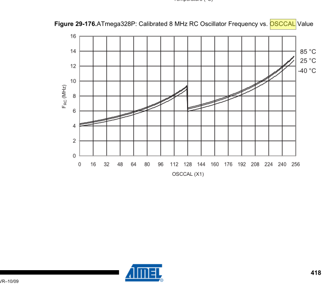
                          I even tried out 57600baut serial data rate on the node thanks to this "calibration" sketch for the internal oscillator.

                          void setup() {
                            Serial.begin(57600);
                            pinMode(A4,OUTPUT);
                            Serial.println(OSCCAL);
                          }
                          
                          // Use hterm to repeatatly send the same message unti you cacn read it
                          void loop() {
                            static uint8_t val = 140;
                            OSCCAL=val;
                            //Serial.println();
                            Serial.print("Osccal= ");  
                            Serial.println(OSCCAL,DEC);
                          
                            delay(500);
                            //digitalWrite(A4,HIGH);
                            //delay(1);
                            //digitalWrite(A4,LOW);
                            //delay(100);
                            while(Serial.available())
                              Serial.write(Serial.read());
                            val++;
                            if(val > 200)
                              val = 140;
                          }
                          

                          Just add this

                          void before()
                          {
                            Serial.begin(MY_BAUD_RATE);
                            OSCCAL=150;
                          }
                          

                          with 150 is the middle of the OSCCAL values where the serial calibration sketch is working. (its working from osccal 140 to osccal 160)

                          0_1472678204477_upload-47191440-9269-4f90-91af-f37336ce037f

                          1 Reply Last reply
                          0
                          • F flopp

                            With this board.txt config

                            atmega328bb.name=ATmega328 on a breadboard (8 MHz internal clock)
                            
                            atmega328bb.upload.protocol=arduino
                            atmega328bb.upload.maximum_size=30720
                            atmega328bb.upload.speed=57600
                            atmega328bb.bootloader.low_fuses=0xE2
                            atmega328bb.bootloader.high_fuses=0xDA
                            atmega328bb.bootloader.extended_fuses=0x06
                            atmega328bb.bootloader.file=atmega/ATmegaBOOT_168_atmega328_pro_8MHz.hex
                            atmega328bb.bootloader.unlock_bits=0x3F
                            atmega328bb.bootloader.lock_bits=0x0F
                            atmega328bb.build.mcu=atmega328p
                            atmega328bb.build.f_cpu=8000000L
                            atmega328bb.build.core=arduino:arduino
                            atmega328bb.build.variant=arduino:standard
                            atmega328bb.bootloader.tool=arduino:avrdude
                            atmega328bb.upload.tool=arduino:avrdude
                            

                            I can upload with FTDI. When Arduino IDE change from "Compiling sketch" to "Upload", disconnect DTR and it work.
                            With my sketch it was using 12,9 uA when sleep
                            Same result if I change f_cpu to 1000000L

                            F Offline
                            F Offline
                            flopp
                            wrote on last edited by
                            #65

                            @flopp said in [Tutorial] How to burn 1Mhz & 8Mhz bootloader using Arduino IDE 1.6.5-r5:

                            With this board.txt config

                            atmega328bb.name=ATmega328 on a breadboard (8 MHz internal clock)
                            
                            atmega328bb.upload.protocol=arduino
                            atmega328bb.upload.maximum_size=30720
                            atmega328bb.upload.speed=57600
                            atmega328bb.bootloader.low_fuses=0xE2
                            atmega328bb.bootloader.high_fuses=0xDA
                            atmega328bb.bootloader.extended_fuses=0x06
                            atmega328bb.bootloader.file=atmega/ATmegaBOOT_168_atmega328_pro_8MHz.hex
                            atmega328bb.bootloader.unlock_bits=0x3F
                            atmega328bb.bootloader.lock_bits=0x0F
                            atmega328bb.build.mcu=atmega328p
                            atmega328bb.build.f_cpu=8000000L
                            atmega328bb.build.core=arduino:arduino
                            atmega328bb.build.variant=arduino:standard
                            atmega328bb.bootloader.tool=arduino:avrdude
                            atmega328bb.upload.tool=arduino:avrdude
                            

                            I can upload with FTDI. When Arduino IDE change from "Compiling sketch" to "Upload", disconnect DTR and it work.
                            With my sketch it was using 12,9 uA when sleep
                            Same result if I change f_cpu to 1000000L

                            Yesterday I burn with above settings, I had to use 5v to power the pro mini(I don't know if the pro mini is 5 or 3.3v) I had to power it with 5v otherwise I couldn't burn any new bootloader.

                            1 Reply Last reply
                            0
                            • F flopp

                              @dpressle
                              OK will try. Cap minus to GND and cap positive to RTS?

                              EDIT: I am using 1Mhz setup
                              I change the LOW fuse and Extended but what I can see is that my changes only changes the BOD and internal oscillator.

                              low_fuses=0x42
                              extended_fuses=0x06

                              I noticed that my board have high_fuses=0xde, this setting the 1MHz board also have but not 8MHz. This mean that I dont have any space for Bootloader, can this be my problem?

                              GertSandersG Offline
                              GertSandersG Offline
                              GertSanders
                              Hardware Contributor
                              wrote on last edited by
                              #66

                              @flopp

                              To use the FTDI connection:

                              You need a ceramic cap (not polarised).

                              RTS - CAP - RESET pin of ATMEGA

                              RESET pin needs a pull up resistor of 10K, connect as follows: VCC - 10K resistor - RESET pin of ATMEGA

                              1 Reply Last reply
                              0
                              • MasMatM Offline
                                MasMatM Offline
                                MasMat
                                wrote on last edited by MasMat
                                #67

                                Help!
                                I semi-followed this thread but also built a shield like this:
                                http://www.instructables.com/id/Arduino-UNO-as-AtMega328P-Programmer/

                                For the Uno, the ArduinoISP sketch goes fine. After that, I connect the shield and 328p and upload stuff.
                                Since my build has 3.3V regulated power (using PCB My Slim 2AA Battery Node..but I can sneak wires to it easily so no need for batteries), I selected 'Board -> Pro Mini' and type '3.3V 8Mhz'. Burn bootloader goes fine, no errors. Upload sketch using programmer (Arduino as ISP) also uploads fine.
                                When I plug it in (USB FTDI-clone 3.3V selected) and see serial monitor, it remains blank. Nor does the node work when plugged into power.

                                Anybody else try this? Ideas? The slim node has all caps and resistor connected.

                                EDIT:
                                I used the recommended board download from 8Mhz instructions and bingo, it's working...partly. Have to check radio wiring.
                                Should just follow instructions and not go off on my own......

                                MasMatM 1 Reply Last reply
                                0
                                • MasMatM MasMat

                                  Help!
                                  I semi-followed this thread but also built a shield like this:
                                  http://www.instructables.com/id/Arduino-UNO-as-AtMega328P-Programmer/

                                  For the Uno, the ArduinoISP sketch goes fine. After that, I connect the shield and 328p and upload stuff.
                                  Since my build has 3.3V regulated power (using PCB My Slim 2AA Battery Node..but I can sneak wires to it easily so no need for batteries), I selected 'Board -> Pro Mini' and type '3.3V 8Mhz'. Burn bootloader goes fine, no errors. Upload sketch using programmer (Arduino as ISP) also uploads fine.
                                  When I plug it in (USB FTDI-clone 3.3V selected) and see serial monitor, it remains blank. Nor does the node work when plugged into power.

                                  Anybody else try this? Ideas? The slim node has all caps and resistor connected.

                                  EDIT:
                                  I used the recommended board download from 8Mhz instructions and bingo, it's working...partly. Have to check radio wiring.
                                  Should just follow instructions and not go off on my own......

                                  MasMatM Offline
                                  MasMatM Offline
                                  MasMat
                                  wrote on last edited by
                                  #68

                                  Continuing on...I need help getting my Atmega328P-PU to work.

                                  I'm able to burn the bootloader (8MHz on breadboard) and upload sketch ("using programmer"). However when I power the PCB, the sketch doesn't run. I soldered on a LED and uploaded BlinkWithoutDelay, just to verify that it works, but does not. I measured power and all connections. I'm powering with regulated 3.3V.

                                  To make things more weird, I connected FTDI to one node and with that connection it works fine. But when powering from pins, nothing (again using regulated 3.3V.

                                  1 Reply Last reply
                                  0
                                  • electrikE Offline
                                    electrikE Offline
                                    electrik
                                    wrote on last edited by
                                    #69

                                    That sounds more like your power connections are not good. You should check them again.
                                    Or perhaps the capacitor of the ftdi makes the difference, and you should add one in your circuit.
                                    Are the atmegas genuine or can they be fake ones?

                                    MasMatM 1 Reply Last reply
                                    0
                                    • electrikE electrik

                                      That sounds more like your power connections are not good. You should check them again.
                                      Or perhaps the capacitor of the ftdi makes the difference, and you should add one in your circuit.
                                      Are the atmegas genuine or can they be fake ones?

                                      MasMatM Offline
                                      MasMatM Offline
                                      MasMat
                                      wrote on last edited by
                                      #70

                                      @electrik Everything's 100% chinese :)
                                      I checked power at all terminals and the atmega-connections, as well as radio hookup etc. I have all the caps on "My Slim Node" (4x 0,1yF and 4,7 yF). I normally get better power thru regulators than with FTDI but I did check that originally.

                                      I built two like this, same type of problem. I have Gert Sanders's "boards" installed. Is there a very basic setup I could try? I'm having trouble figuring out all the options that are available. All I want is Atmega working like a normal 3.3v/8MHz Arduino.

                                      1 Reply Last reply
                                      0
                                      • electrikE Offline
                                        electrikE Offline
                                        electrik
                                        wrote on last edited by
                                        #71

                                        Did you read this?
                                        https://forum.mysensors.org/topic/9388/atmega328p-au-counterfeit/15

                                        1 Reply Last reply
                                        0
                                        • MasMatM Offline
                                          MasMatM Offline
                                          MasMat
                                          wrote on last edited by MasMat
                                          #72

                                          I have now. I always have that nagging feeling...
                                          But after MANY iterations, finally success. At least partly. :v:

                                          BlinkWithoutDelay works AND mysensors sketch as well (will do more testing...).
                                          What made it work, if anyone else struggles with this:

                                          -connect uno (to computer-linux), board:uno, upload ArduinoISP, disconnect
                                          -add shield to uno and atmega328p-pu to shield, connect to computer, board: "8mhz on breadboard", "programmer: "Arduino as ISP", burn bootloader, disconnect
                                          -board: Uno, connect as above, "upload sketch using programmer", disconnect EDIT this last part appears to work but internal clock is all messed up. Bootloader works fine like this.

                                          The magic happened after I changed the board back to Uno after burning bootloader. Why is beyond me, but maybe some arduino-ninja can figure it out.

                                          1 Reply Last reply
                                          1
                                          Reply
                                          • Reply as topic
                                          Log in to reply
                                          • Oldest to Newest
                                          • Newest to Oldest
                                          • Most Votes


                                          17

                                          Online

                                          11.7k

                                          Users

                                          11.2k

                                          Topics

                                          113.0k

                                          Posts


                                          Copyright 2019 TBD   |   Forum Guidelines   |   Privacy Policy   |   Terms of Service
                                          • Login

                                          • Don't have an account? Register

                                          • Login or register to search.
                                          • First post
                                            Last post
                                          0
                                          • MySensors
                                          • OpenHardware.io
                                          • Categories
                                          • Recent
                                          • Tags
                                          • Popular