[Tutorial] How to burn 1Mhz & 8Mhz bootloader using Arduino IDE 1.6.5-r5
-
@siod
For OTA you need to flash the boot loaders that allow this. The standard boot loaders do not have this ability to OTA update.@GertSanders said:
@siod
For OTA you need to flash the boot loaders that allow this. The standard boot loaders do not have this ability to OTA update.Ok, but after the new release of mysensors ver 2.0 lib and my wish to update my gw and sensor nodes I would like to add OTA update ability as well for upcoming updates.
- So does a 1 MHz Bootloader with OTA exist that is compatible to the one from above?
- Could OTA easily be added to the above 1MHz Bootloader?
- Should i just use the "ATmega328 internal 8Mhz with MYSBootloader" instead of the above mentioned bootloaders?
-
Recently I read a lot about the 0ms, 4.1ms, 65ms start-up time of the low fuses.
I thought adding a small example to prove that the 65ms start-up time is apparently only important during initial powerup.
Used library: https://github.com/rocketscream/Low-Power
Testcode:
#include <LowPower.h>

// the setup function runs once when you press reset or power the board
void setup() {
  // initialize digital pin 13 as an output.
  pinMode(13, OUTPUT);
  Serial.begin(19200);
}

// the loop function runs over and over again forever
void loop() {

  LowPower.powerDown(SLEEP_15Ms, ADC_OFF, BOD_OFF);
  Serial.write(".");
  Serial.flush();
}
First dot:
Second dot:
= 15ms (sleep) + 2ms (serial communication)
~17ms including overhead for sending serial commandI will try out your bootloader and I can only say that it looks promising
-
I ran into an rather strange problem.
Mygateway is using esp8266_mqtt_client @ 80Mhz and my node is using the 1mhz bootloader.
If I enable debug logging on the gateway everything is working fine.
Upon disabling debug logging on the gateway and enabling debug lobbing on the node I get this:
TSP:PING:SEND (dest=0)<\n>
TSP:MSG:SEND 11-11-0-0 s=255,c=3,t=24,pt=1,l=1,sg=0,ft=0,st=ok:1<\n>
TSP:CHKUPL:FAIL (hops=255)<\n>
!TSM:UPL:FAIL<\n>
Note that I don't use hardware ack. My assumption is that it takes too long to switch from send mode on the node to receive mode and that the gateway is responding too "fast" for the 1mhz node. Could this be possible?
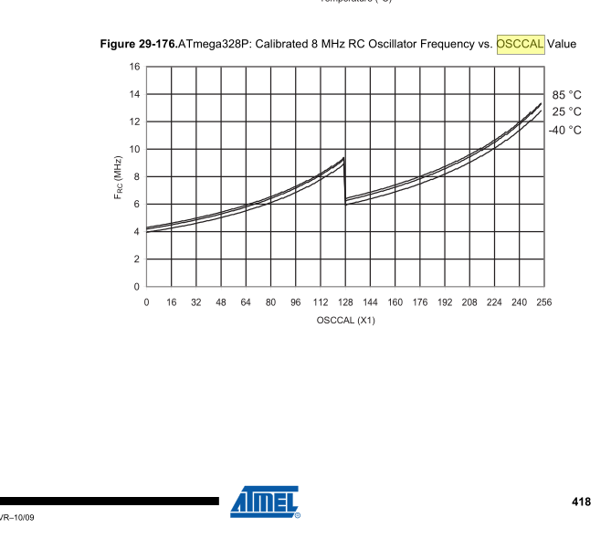
I even tried out 57600baut serial data rate on the node thanks to this "calibration" sketch for the internal oscillator.
void setup() {
  Serial.begin(57600);
  pinMode(A4,OUTPUT);
  Serial.println(OSCCAL);
}

// Use hterm to repeatatly send the same message unti you cacn read it
void loop() {
  static uint8_t val = 140;
  OSCCAL=val;
  //Serial.println();
  Serial.print("Osccal= ");
  Serial.println(OSCCAL,DEC);

  delay(500);
  //digitalWrite(A4,HIGH);
  //delay(1);
  //digitalWrite(A4,LOW);
  //delay(100);
  while(Serial.available())
    Serial.write(Serial.read());
  val++;
  if(val > 200)
    val = 140;
}
Just add this
void before()
{
  Serial.begin(MY_BAUD_RATE);
  OSCCAL=150;
}
with 150 is the middle of the OSCCAL values where the serial calibration sketch is working. (its working from osccal 140 to osccal 160)
-
With this board.txt config
atmega328bb.name=ATmega328 on a breadboard (8 MHz internal clock)

atmega328bb.upload.protocol=arduino
atmega328bb.upload.maximum_size=30720
atmega328bb.upload.speed=57600
atmega328bb.bootloader.low_fuses=0xE2
atmega328bb.bootloader.high_fuses=0xDA
atmega328bb.bootloader.extended_fuses=0x06
atmega328bb.bootloader.file=atmega/ATmegaBOOT_168_atmega328_pro_8MHz.hex
atmega328bb.bootloader.unlock_bits=0x3F
atmega328bb.bootloader.lock_bits=0x0F
atmega328bb.build.mcu=atmega328p
atmega328bb.build.f_cpu=8000000L
atmega328bb.build.core=arduino:arduino
atmega328bb.build.variant=arduino:standard
atmega328bb.bootloader.tool=arduino:avrdude
atmega328bb.upload.tool=arduino:avrdude
I can upload with FTDI. When Arduino IDE change from "Compiling sketch" to "Upload", disconnect DTR and it work.
With my sketch it was using 12,9 uA when sleep
Same result if I change f_cpu to 1000000L@flopp said in [Tutorial] How to burn 1Mhz & 8Mhz bootloader using Arduino IDE 1.6.5-r5:
With this board.txt config
atmega328bb.name=ATmega328 on a breadboard (8 MHz internal clock)

atmega328bb.upload.protocol=arduino
atmega328bb.upload.maximum_size=30720
atmega328bb.upload.speed=57600
atmega328bb.bootloader.low_fuses=0xE2
atmega328bb.bootloader.high_fuses=0xDA
atmega328bb.bootloader.extended_fuses=0x06
atmega328bb.bootloader.file=atmega/ATmegaBOOT_168_atmega328_pro_8MHz.hex
atmega328bb.bootloader.unlock_bits=0x3F
atmega328bb.bootloader.lock_bits=0x0F
atmega328bb.build.mcu=atmega328p
atmega328bb.build.f_cpu=8000000L
atmega328bb.build.core=arduino:arduino
atmega328bb.build.variant=arduino:standard
atmega328bb.bootloader.tool=arduino:avrdude
atmega328bb.upload.tool=arduino:avrdude
I can upload with FTDI. When Arduino IDE change from "Compiling sketch" to "Upload", disconnect DTR and it work.
With my sketch it was using 12,9 uA when sleep
Same result if I change f_cpu to 1000000LYesterday I burn with above settings, I had to use 5v to power the pro mini(I don't know if the pro mini is 5 or 3.3v) I had to power it with 5v otherwise I couldn't burn any new bootloader.
-
@dpressle
OK will try. Cap minus to GND and cap positive to RTS?EDIT: I am using 1Mhz setup
I change the LOW fuse and Extended but what I can see is that my changes only changes the BOD and internal oscillator.low_fuses=0x42
extended_fuses=0x06I noticed that my board have high_fuses=0xde, this setting the 1MHz board also have but not 8MHz. This mean that I dont have any space for Bootloader, can this be my problem?
To use the FTDI connection:
You need a ceramic cap (not polarised).
RTS - CAP - RESET pin of ATMEGA
RESET pin needs a pull up resistor of 10K, connect as follows: VCC - 10K resistor - RESET pin of ATMEGA
-
Help!
I semi-followed this thread but also built a shield like this:
http://www.instructables.com/id/Arduino-UNO-as-AtMega328P-Programmer/For the Uno, the ArduinoISP sketch goes fine. After that, I connect the shield and 328p and upload stuff.
Since my build has 3.3V regulated power (using PCB My Slim 2AA Battery Node..but I can sneak wires to it easily so no need for batteries), I selected 'Board -> Pro Mini' and type '3.3V 8Mhz'. Burn bootloader goes fine, no errors. Upload sketch using programmer (Arduino as ISP) also uploads fine.
When I plug it in (USB FTDI-clone 3.3V selected) and see serial monitor, it remains blank. Nor does the node work when plugged into power.Anybody else try this? Ideas? The slim node has all caps and resistor connected.
EDIT:
I used the recommended board download from 8Mhz instructions and bingo, it's working...partly. Have to check radio wiring.
Should just follow instructions and not go off on my own...... -
Help!
I semi-followed this thread but also built a shield like this:
http://www.instructables.com/id/Arduino-UNO-as-AtMega328P-Programmer/For the Uno, the ArduinoISP sketch goes fine. After that, I connect the shield and 328p and upload stuff.
Since my build has 3.3V regulated power (using PCB My Slim 2AA Battery Node..but I can sneak wires to it easily so no need for batteries), I selected 'Board -> Pro Mini' and type '3.3V 8Mhz'. Burn bootloader goes fine, no errors. Upload sketch using programmer (Arduino as ISP) also uploads fine.
When I plug it in (USB FTDI-clone 3.3V selected) and see serial monitor, it remains blank. Nor does the node work when plugged into power.Anybody else try this? Ideas? The slim node has all caps and resistor connected.
EDIT:
I used the recommended board download from 8Mhz instructions and bingo, it's working...partly. Have to check radio wiring.
Should just follow instructions and not go off on my own......Continuing on...I need help getting my Atmega328P-PU to work.
I'm able to burn the bootloader (8MHz on breadboard) and upload sketch ("using programmer"). However when I power the PCB, the sketch doesn't run. I soldered on a LED and uploaded BlinkWithoutDelay, just to verify that it works, but does not. I measured power and all connections. I'm powering with regulated 3.3V.
To make things more weird, I connected FTDI to one node and with that connection it works fine. But when powering from pins, nothing (again using regulated 3.3V.
-
That sounds more like your power connections are not good. You should check them again.
Or perhaps the capacitor of the ftdi makes the difference, and you should add one in your circuit.
Are the atmegas genuine or can they be fake ones?@electrik Everything's 100% chinese :)
I checked power at all terminals and the atmega-connections, as well as radio hookup etc. I have all the caps on "My Slim Node" (4x 0,1yF and 4,7 yF). I normally get better power thru regulators than with FTDI but I did check that originally.I built two like this, same type of problem. I have Gert Sanders's "boards" installed. Is there a very basic setup I could try? I'm having trouble figuring out all the options that are available. All I want is Atmega working like a normal 3.3v/8MHz Arduino.
-
Did you read this?
https://forum.mysensors.org/topic/9388/atmega328p-au-counterfeit/15 -
I have now. I always have that nagging feeling...
But after MANY iterations, finally success. At least partly. :v:BlinkWithoutDelay works AND mysensors sketch as well (will do more testing...).
What made it work, if anyone else struggles with this:-connect uno (to computer-linux), board:uno, upload ArduinoISP, disconnect
-add shield to uno and atmega328p-pu to shield, connect to computer, board: "8mhz on breadboard", "programmer: "Arduino as ISP", burn bootloader, disconnect
-board: Uno, connect as above, "upload sketch using programmer", disconnectEDIT this last part appears to work but internal clock is all messed up. Bootloader works fine like this.The magic happened after I changed the board back to Uno after burning bootloader. Why is beyond me, but maybe some arduino-ninja can figure it out.
-
As I recall depending of frequency you need to adjust sketch upload baudrate, Maybe "uno" board have the "correct" baudrate defined for your frequency
https://forum.arduino.cc/index.php?topic=92663.0 -
Can someone help me with these questions?
I want the Slim Node to function "like a 3.3/8mhz pro mini" for MySensors home autom applications. So I can upload sketches thru ftdi-pins. Since I also use Pro Minis, I would not want change the mysensors library (serial baud).- if I load the bootloader with a 8mhz crystal on the breadboard, does my barebones Slim node need a crystal too?
- If I set serial.begin in the sketch, does it override the MySensors default? So I could have that for slim node sketches.
- What kind of nodes would be problematic without crystal use? Repeater?
- Is it possible to Uno+breadboard just bootload all atmega328p's and then just solder onto SlimNode and use ftdi for uploading sketches (as I would normally to a Pro Mini)? In other words do I have to rethink the whole thing.
EDIT, to help others
- if the bootloader is not set for crystal, it's not needed.
- yes
- ? Repeaters work fine.
- yes.
My biggest problem was a capacitor missing between RST and GND when uploading bootloaders. After adding that to my shield, everything works.
Now I bootload 1Mhz (battery nodes) and 8Mhz (non-bat) once I get them and then program them with the FTDI when I build the nodes.
-
Can someone help me with these questions?
I want the Slim Node to function "like a 3.3/8mhz pro mini" for MySensors home autom applications. So I can upload sketches thru ftdi-pins. Since I also use Pro Minis, I would not want change the mysensors library (serial baud).- if I load the bootloader with a 8mhz crystal on the breadboard, does my barebones Slim node need a crystal too?
- If I set serial.begin in the sketch, does it override the MySensors default? So I could have that for slim node sketches.
- What kind of nodes would be problematic without crystal use? Repeater?
- Is it possible to Uno+breadboard just bootload all atmega328p's and then just solder onto SlimNode and use ftdi for uploading sketches (as I would normally to a Pro Mini)? In other words do I have to rethink the whole thing.
EDIT, to help others
- if the bootloader is not set for crystal, it's not needed.
- yes
- ? Repeaters work fine.
- yes.
My biggest problem was a capacitor missing between RST and GND when uploading bootloaders. After adding that to my shield, everything works.
Now I bootload 1Mhz (battery nodes) and 8Mhz (non-bat) once I get them and then program them with the FTDI when I build the nodes.
@masmat I don't know about the other questions, but for the baud rate you can use
#define MY_BAUD_RATE 9600(or some other speed that you want to use)
Documentation: https://www.mysensors.org/apidocs/group__SerialDebugGrpPub.html#ga36a01c35b670e1f0797fd63d2ad76ed2 -
First of all thanks to all who worked on this tutorial and bootloaders. i got fascinated about 8mhz and 1mhz with internal clock after reading this tutorial.
Some might say 1mhz 8 times slower then 8mhz hence need longer awake time to do perform task before it can go back to sleep and consumes more power but what i found: point is not it takes 8 times longer to perform task but it can run it on battery longer and on lower voltage when battery ist at its peak youth.
Anyway i wanted to share my experience and errors i had and the fix i found after googling around and spending hours trying to figure out what is going on.
if you follow instructions as it is then you will end up with second boards.txt file located at C:\Program Files (x86)\Arduino\hardware\breadboard\avr\boards.txt, this file contact info about ATmegaBOOT_168_atmega328_pro_8MHz.hex only. So far so good and it works but for some reason when i try to add 1mhz bootloader to C:\Program Files (x86)\Arduino\hardware\arduino\avr\boards.txt it just wouldn't work, the 1mhz bootloader wouldn't show in in board selection option but if i add info about 1mhz bootloader to "C:\Program Files (x86)\Arduino\hardware\breadboard\avr\boards.txt" then i could see option for "APM Optiboot internal 1MHz noBOD 9600baud" but when i try to burn this bootloader i get all sorts of error on burning bootloader, one of the error: Could not find tool avrdude (sorry didn't copy all error messages)
Then some forums suggest to start clean i.e uninstall Arduino ID and reinstall but simply uninstalling and reinstalling ID doesn't work you need to delete Arduino15 folder from following location(s) and reinstall Arduino ID:
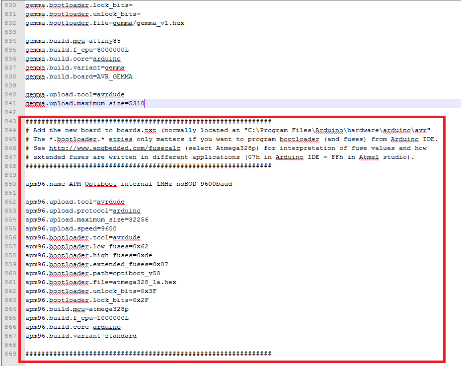
C:\Users(username)\AppData\Local\Arduino15 or C:\Users<username>\AppData\Roaming\Arduino15 or C:\Users<username>\AppData\Local\Arduino15What i think is best to keep your boards.txt file in one location and modify it and add bootloaders in it and this worked for me. Simply copy your bootloaders to C:\Program Files (x86)\Arduino\hardware\arduino\avr\bootloaders and modify C:\Program Files (x86)\Arduino\hardware\arduino\avr\boards.txt for additional bootloaders.
here is my boards.txt############################################################## # Add the new board to boards.txt (normally located at "C:\Program Files\Arduino\hardware\arduino\avr" # The *.bootloader.* etries only matters if you want to program bootloader (and fuses) from Arduino IDE. # See http://www.engbedded.com/fusecalc (select Atmega328p) for interpretation of fuse values and how # extended fuses are written in different applications (07h in Arduino IDE = FFh in Atmel studio). ############################################################## apm96.name=APM Optiboot internal 1MHz noBOD 9600baud apm96.upload.tool=avrdude apm96.upload.protocol=arduino apm96.upload.maximum_size=32256 apm96.upload.speed=9600 apm96.bootloader.tool=avrdude apm96.bootloader.low_fuses=0x62 apm96.bootloader.high_fuses=0xde # all the possible values: #bootloader.extended_fuses=0x04 -> BOD at 4.3V #bootloader.extended_fuses=0x05 -> BOD at 2.7V #bootloader.extended_fuses=0x06 -> BOD at 1.8V #bootloader.extended_fuses=0x07 -> BOD disabled apm96.bootloader.extended_fuses=0x07 apm96.bootloader.path=optiboot_v50 apm96.bootloader.file=atmega328_1a.hex apm96.bootloader.unlock_bits=0x3F apm96.bootloader.lock_bits=0x2F apm96.build.mcu=atmega328p apm96.build.f_cpu=1000000L apm96.build.core=arduino apm96.build.variant=standard ############################################################## ############################################################## atmega328bb.name=ATmega328 on a breadboard (8 MHz internal clock) atmega328bb.upload.protocol=arduino atmega328bb.upload.maximum_size=30720 atmega328bb.upload.speed=57600 atmega328bb.bootloader.low_fuses=0xE2 atmega328bb.bootloader.high_fuses=0xDA atmega328bb.bootloader.extended_fuses=0x05 atmega328bb.bootloader.file=atmega/ATmegaBOOT_168_atmega328_pro_8MHz.hex atmega328bb.bootloader.unlock_bits=0x3F atmega328bb.bootloader.lock_bits=0x0F atmega328bb.build.mcu=atmega328p atmega328bb.build.f_cpu=8000000L atmega328bb.build.core=arduino:arduino atmega328bb.build.variant=arduino:standard atmega328bb.bootloader.tool=arduino:avrdude atmega328bb.upload.tool=arduino:avrdude``` -
Dear Sir,
I'm trying to use the 8MHz bootloader, but I kindly ask you in detail where I've to copy the files extracted from the zip file breadboard-1-6-x.zip.Actually I'm using an Arduino IDE 1.8.10, the sentence that I need some explanation/confirmation is the following one:
"Open your Arduino folder path and move the breadboard folder from the zip archive to the "hardware" folder of your Arduino sketchbook."
is the Arduino sketchbook folder located at the path listed from:
File=>Preferences=>Settings
at the text field with label "Sketchbook location"?
At this path I've no other "hardware" directory, just only a libraries folder, so if this is the right path I've just to simply copy and paste the "breadboard" folder into this one, I'm correct?
Thanks!
Fire -
Dear Sir,
I'm trying to use the 8MHz bootloader, but I kindly ask you in detail where I've to copy the files extracted from the zip file breadboard-1-6-x.zip.Actually I'm using an Arduino IDE 1.8.10, the sentence that I need some explanation/confirmation is the following one:
"Open your Arduino folder path and move the breadboard folder from the zip archive to the "hardware" folder of your Arduino sketchbook."
is the Arduino sketchbook folder located at the path listed from:
File=>Preferences=>Settings
at the text field with label "Sketchbook location"?
At this path I've no other "hardware" directory, just only a libraries folder, so if this is the right path I've just to simply copy and paste the "breadboard" folder into this one, I'm correct?
Thanks!
Fire@FIRE-FOX The answer depends a little on what OS you're using.
In linux I have an Arduino-folder where the program files (not necessarily the sketches) are AND a hardware folder. Also on OSX I have an Arduino-folder (where I have my sketch-directories and libraries and hardware.
Locate the hardware-folder (use whatever search-option your OS has) and you can pretty easily figure out where the breadboard-directory goes.I wish you luck with the bootloader programming. I went crazy a couple of times but once I got the routine down, it's worth the trouble.
-
Dear Sir,
I'm trying to use the 8MHz bootloader, but I kindly ask you in detail where I've to copy the files extracted from the zip file breadboard-1-6-x.zip.Actually I'm using an Arduino IDE 1.8.10, the sentence that I need some explanation/confirmation is the following one:
"Open your Arduino folder path and move the breadboard folder from the zip archive to the "hardware" folder of your Arduino sketchbook."
is the Arduino sketchbook folder located at the path listed from:
File=>Preferences=>Settings
at the text field with label "Sketchbook location"?
At this path I've no other "hardware" directory, just only a libraries folder, so if this is the right path I've just to simply copy and paste the "breadboard" folder into this one, I'm correct?
Thanks!
Fire@FIRE-FOX Today I should not go that way, see https://forum.mysensors.org/topic/2067/my-slim-2aa-battery-node. In the first topic you will see Update1 and to use the github project MiniCore. Much easier to use!
In the readme of the MiniCore github you will find how to install and how to use. -
hi,
i am using pro mini, i installed the blink code, pro mini does not work at 2.3v. I burned minicore bootloader(1Mhz-1,98).
my purpose: running pro mini up to 1.8v and saving power.
The blink code continues to run. no longer working pro mini 2.3V. but I can't upload new code.
What can I do to use it again?the error he gave:
avrdude: stk500_recv(): programmer is not responding avrdude: stk500_getsync() attempt 1 of 10: not in sync: resp=0x03 avrdude: stk500_recv(): programmer is not responding avrdude: stk500_getsync() attempt 2 of 10: not in sync: resp=0x03 avrdude: stk500_recv(): programmer is not responding avrdude: stk500_getsync() attempt 3 of 10: not in sync: resp=0x03 avrdude: stk500_recv(): programmer is not responding avrdude: stk500_getsync() attempt 4 of 10: not in sync: resp=0x03 Karta yüklenirken sorun oluştu. Tavsiyeler için http://www.arduino.cc/en/Guide/Troubleshooting#upload adresine göz atabilirsiniz. avrdude: stk500_recv(): programmer is not responding avrdude: stk500_getsync() attempt 5 of 10: not in sync: resp=0x03 avrdude: stk500_recv(): programmer is not responding avrdude: stk500_getsync() attempt 6 of 10: not in sync: resp=0x03 avrdude: stk500_recv(): programmer is not responding avrdude: stk500_getsync() attempt 7 of 10: not in sync: resp=0x03 avrdude: stk500_recv(): programmer is not responding avrdude: stk500_getsync() attempt 8 of 10: not in sync: resp=0x03 avrdude: stk500_recv(): programmer is not responding avrdude: stk500_getsync() attempt 9 of 10: not in sync: resp=0x03 avrdude: stk500_recv(): programmer is not responding avrdude: stk500_getsync() attempt 10 of 10: not in sync: resp=0x03 -
hi,
i am using pro mini, i installed the blink code, pro mini does not work at 2.3v. I burned minicore bootloader(1Mhz-1,98).
my purpose: running pro mini up to 1.8v and saving power.
The blink code continues to run. no longer working pro mini 2.3V. but I can't upload new code.
What can I do to use it again?the error he gave:
avrdude: stk500_recv(): programmer is not responding
avrdude: stk500_getsync() attempt 1 of 10: not in sync: resp=0x03
avrdude: stk500_recv(): programmer is not responding
avrdude: stk500_getsync() attempt 2 of 10: not in sync: resp=0x03
avrdude: stk500_recv(): programmer is not responding
avrdude: stk500_getsync() attempt 3 of 10: not in sync: resp=0x03
avrdude: stk500_recv(): programmer is not responding
avrdude: stk500_getsync() attempt 4 of 10: not in sync: resp=0x03
Karta yüklenirken sorun oluştu. Tavsiyeler için http://www.arduino.cc/en/Guide/Troubleshooting#upload adresine göz atabilirsiniz.
avrdude: stk500_recv(): programmer is not responding
avrdude: stk500_getsync() attempt 5 of 10: not in sync: resp=0x03
avrdude: stk500_recv(): programmer is not responding
avrdude: stk500_getsync() attempt 6 of 10: not in sync: resp=0x03
avrdude: stk500_recv(): programmer is not responding
avrdude: stk500_getsync() attempt 7 of 10: not in sync: resp=0x03
avrdude: stk500_recv(): programmer is not responding
avrdude: stk500_getsync() attempt 8 of 10: not in sync: resp=0x03
avrdude: stk500_recv(): programmer is not responding
avrdude: stk500_getsync() attempt 9 of 10: not in sync: resp=0x03
avrdude: stk500_recv(): programmer is not responding
avrdude: stk500_getsync() attempt 10 of 10: not in sync: resp=0x03

Hello! It looks like you're interested in this conversation, but you don't have an account yet.
Getting fed up of having to scroll through the same posts each visit? When you register for an account, you'll always come back to exactly where you were before, and choose to be notified of new replies (either via email, or push notification). You'll also be able to save bookmarks and upvote posts to show your appreciation to other community members.
With your input, this post could be even better 💗
Register Login