💬 MySensors Stable Node
-
Ermm... how do I know it works correctly ?, and if it doesn't work correctly which 1M resistor do I have to use ?
Thanks for your help !!!
Alex
@Slorf NRF oscillator can work or not (or could stop after some time). If problems appear use any 1m resistor (0402 or 0603 if you can solder it). Do not worry. It is the last stage (after nrf soldering and atmega programming).
Can you provide link to your nrf chip(where you buy it)? I want to check it. -
Sorry for the late reply, our second son was born just 2 weeks ago.... no sleep anymore :-)
It looks like this one, except mines it labelled: 0935VI, the one on the link 0935VJ
-
Sorry for the late reply, our second son was born just 2 weeks ago.... no sleep anymore :-)
It looks like this one, except mines it labelled: 0935VI, the one on the link 0935VJ
-
Sorry for the late reply, our second son was born just 2 weeks ago.... no sleep anymore :-)
It looks like this one, except mines it labelled: 0935VI, the one on the link 0935VJ
-
@koresh Just created a light sensor from one of the boards I bought from you. It works great !
I had to do some tweaking with the serial monitor speed from my arduino IDE (I had to double the speed which was set in the code or something)
I also had to press the reset button just before uploading of the sketch started.
Apart from that: Great !
Thanks ! -
@koresh Just created a light sensor from one of the boards I bought from you. It works great !
I had to do some tweaking with the serial monitor speed from my arduino IDE (I had to double the speed which was set in the code or something)
I also had to press the reset button just before uploading of the sketch started.
Apart from that: Great !
Thanks !@Sander-Teunissen
Thanks to your responce.
I'm sorry to hear you faced some hardware problem. Of course the board must restart itself. It may be couse of low quality of mounting first boards or it was damaged during delivery :(
May be you used incorrect usb-ttl converters boards without correct dtr line? I faced them year ago.. it was bad surprise ) -
@Sander-Teunissen
Thanks to your responce.
I'm sorry to hear you faced some hardware problem. Of course the board must restart itself. It may be couse of low quality of mounting first boards or it was damaged during delivery :(
May be you used incorrect usb-ttl converters boards without correct dtr line? I faced them year ago.. it was bad surprise )@Koresh No problems. I am happy working with them.
-
@Koresh I guess I already know the answer, but this board works with 3.3 volts ? If I want to connect something like this:
https://www.mysensors.org/build/motion ,which works only on 5V I'd need to add a step up converter ?Sander.
-
@Koresh I guess I already know the answer, but this board works with 3.3 volts ? If I want to connect something like this:
https://www.mysensors.org/build/motion ,which works only on 5V I'd need to add a step up converter ?Sander.
@Sander-Teunissen said:
@Koresh I guess I already know the answer, but this board works with 3.3 volts ? If I want to connect something like this:
https://www.mysensors.org/build/motion ,which works only on 5V I'd need to add a step up converter ?Sander.
Board contains two 3.3v LDO. You can change one of them to 5v (do not forget check schematic).
-
@Sander-Teunissen you can modify the motion sensor to work on 3.3V (see http://www.instructables.com/id/Convert-a-5v-PIR-Motion-Sensor-to-33v-for-ESP8266/)
-
Hi,
I aasembled your node, but the radio chip version is not the + one. After burning the MYS bootloader is prints the debug in serial:
60110 TSM:FAIL:RE-INIT
60112 TSM:INIT
60119 !TSM:INIT:TSP FAIL
60123 TSM:FAIL:CNT=7
60125 TSM:FAIL:PDTAny suggestions?
-
Hi,
I aasembled your node, but the radio chip version is not the + one. After burning the MYS bootloader is prints the debug in serial:
60110 TSM:FAIL:RE-INIT
60112 TSM:INIT
60119 !TSM:INIT:TSP FAIL
60123 TSM:FAIL:CNT=7
60125 TSM:FAIL:PDTAny suggestions?
@Tigroenot said:
Hi,
I aasembled your node, but the radio chip version is not the + one. After burning the MYS bootloader is prints the debug in serial:
60110 TSM:FAIL:RE-INIT
60112 TSM:INIT
60119 !TSM:INIT:TSP FAIL
60123 TSM:FAIL:CNT=7
60125 TSM:FAIL:PDTAny suggestions?
For not the + version you should mount 1M resistor (R21). And check all soldering points of course.
-
I checked everything twice of course. I don't have 0402 1M resistor, the smallest I have is 0805 :)
@Tigroenot said:
I checked everything twice of course. I don't have 0402 1M resistor, the smallest I have is 0805 :)
You can easily solder THD resistor in parallel with Q2 ;)
-
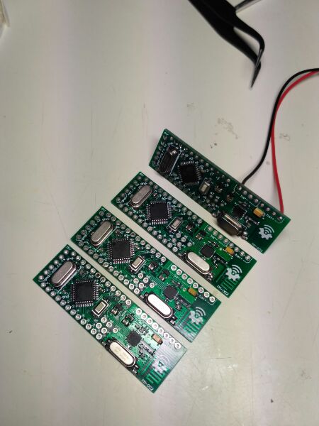
Allright, I have replaced the nrf chips to those with + and... that was it, everything is working very well now :)
Here they are, freshly handmade :)
@Tigroenot
I'm really happy to see your success with these boards. Congratulations! :thumbsup: -
Very nice design ! I wish it was available for sale !
I have a question, though. Would it make sense to mutualize the Crystal between the NRF and the Atmel ?
Hello! It looks like you're interested in this conversation, but you don't have an account yet.
Getting fed up of having to scroll through the same posts each visit? When you register for an account, you'll always come back to exactly where you were before, and choose to be notified of new replies (either via email, or push notification). You'll also be able to save bookmarks and upvote posts to show your appreciation to other community members.
With your input, this post could be even better 💗
Register Login