My New IrrigationController
-
check ospi they have published their BOM
z-wave - Vera -> Domoticz
rfx - Domoticz <- MyDomoAtHome <- Imperihome
mysensors -> mysensors-gw -> Domoticz -
@epierre
power supply unit with LM2596 is rather complicated to build and needs parts which I don't have. I could, of course, buy step down module for around 1-2$. Maybe I'll come back to this solution after this watering season - now is is to late for this. Thanks anyway! -
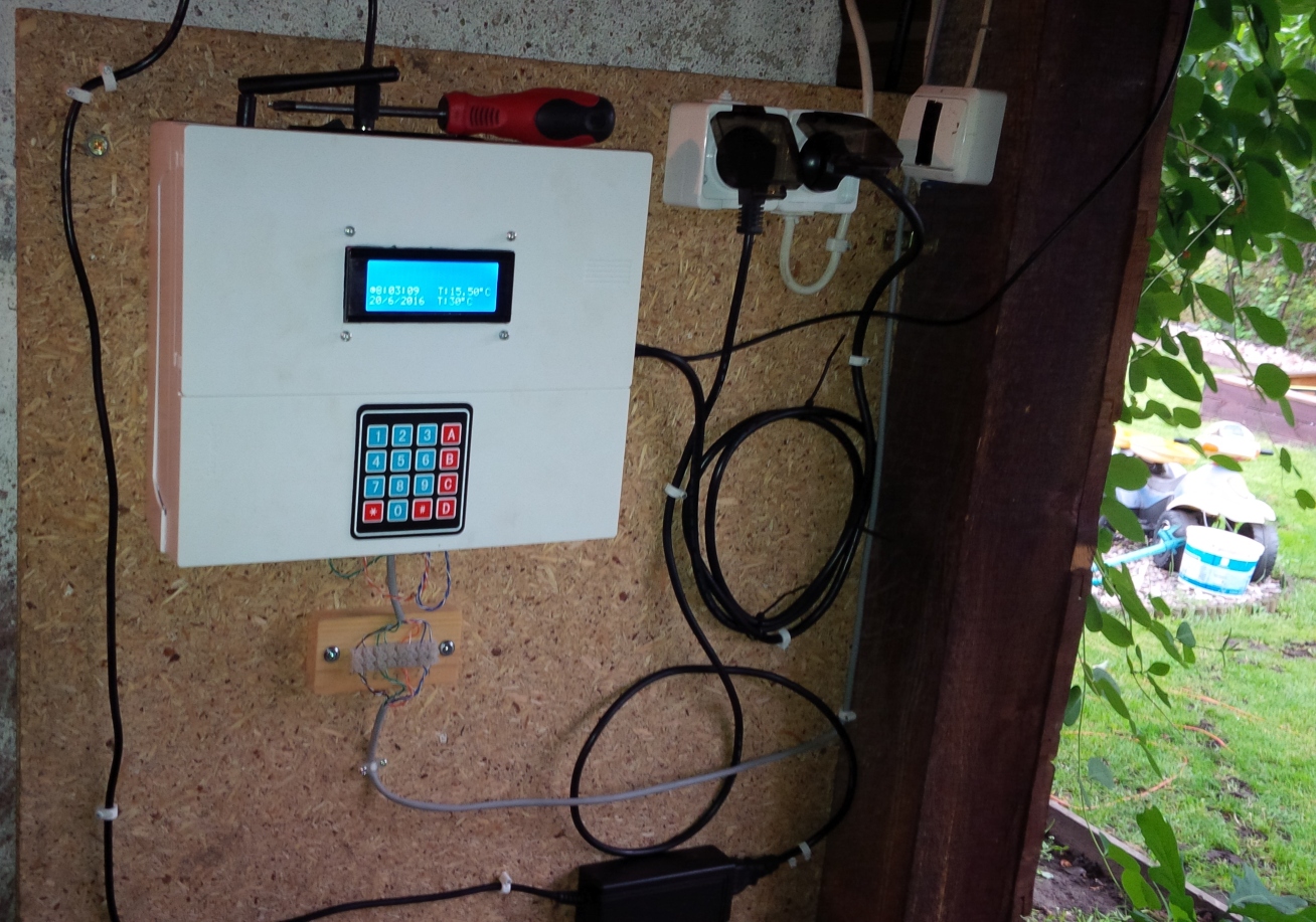
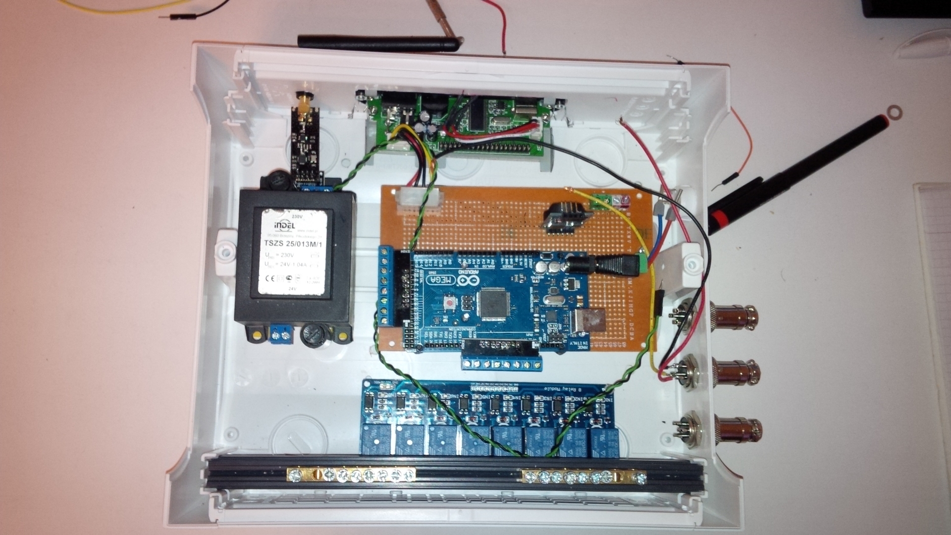
Finally I launched my Irrigation System, there are some small bugs in the code, but can live with it - for now. Have plans how to rebuild this in winter time to be more robust and to look better.
Runs under Domoticz and manually with keypad.
For now it looks like this:
-
@epierre
Started to play with LM2596, I've got sth. like this:
http://www.ebay.com/itm/1pcs-1-23V-30V-DC-DC-Buck-Converter-Step-Down-Module-LM2596-Power-Supply-Output-/400985220074?hash=item5d5c94e3ea:g:o10AAOxy0x1TVSpDAdded diode bridge between transformer and this converter. But my concern is that I've some big voltage peaks the the output of it. It happens when I'm opening/closing valves (AC solenoids) connected to this transformer.
Set this converter to 12V DC but my readings are sometimes around 20V DC and I am affraid that I could destroy by Arduino.
Do you (anyone) have any suggestion ? -
Just wondering, could you not set your zones up as an array. This would reduce the size a little and should also free up memory for variables.
@gbgent_nc
Yes I could and did already because have to use ProMini [my MEGA2560 was killed ;) ].
Anyway plan is now to use 2xProMini., one for LCD, Keyboard, relays and second for temperature x2, water meter, rain sensor and relay for pump. -
@fets
Manufacturer is RAIN S.p.a Italy, www.rain.it.
Model I use is RN150.
Got them from Leroy Merlin, price was around 11 EUR. -
Last summer during vacation, was quite hot at my place. My green grass in the garden became ... brown and yellow - there was nobody to irrigate and was no rain, of course!
So I made a decision to buy irrigation controller and all that stuff. I wanted to have 7-8 zones, BT or wireless control, temperature and rain based control, RTC, Keypad, etc. The problem was that nobody had it or was to expencive.
So long story short I came up with idea to build one with all those features i need. Without having experience with uC I start to learn (google and youtube) a bit and build some "prototypes". Than IrrigatonController ver 1.0 was ready (December 2015):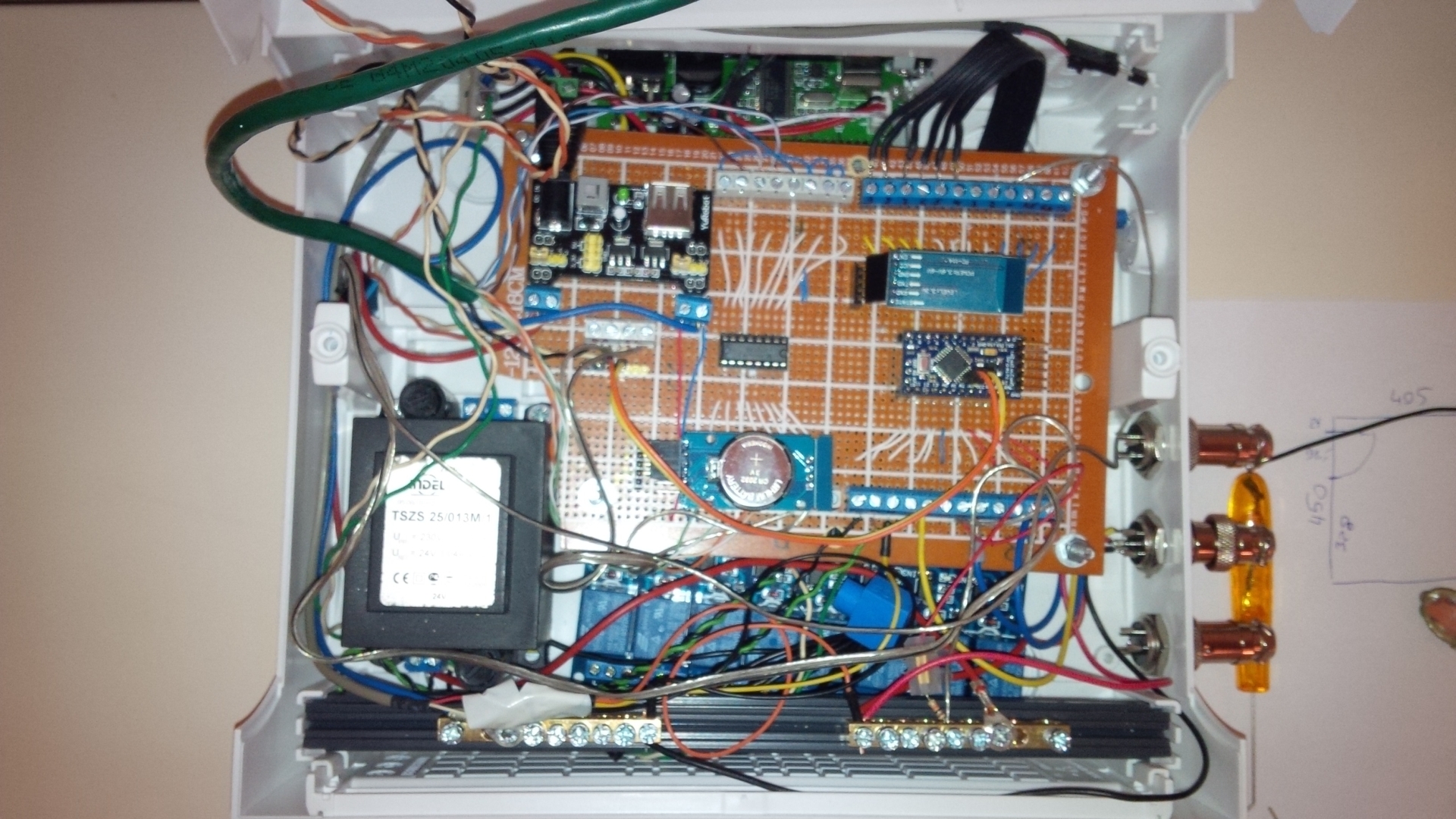
Than I found @petewill IrrigationControler at youtube - but it was to hard for me from software (all this MySensors) and hardware side - I thought!
So I built new one - well it is almost done.
It is tested and working, few things are still missing like running without HA controller and rain sensor. Anyway I post some pictures and script what I've done. At my place it is working under Domoticz and manual (keypad). Tomorrow final wiring!
 .
.Any comments are more than welcome, know that script need some more work - but it is just a beginning.
/**
 * The MySensors Arduino library handles the wireless radio link and protocol
 * between your home built sensors/actuators and HA controller of choice.
 * The sensors forms a self healing radio network with optional repeaters. Each
 * repeater and gateway builds a routing tables in EEPROM which keeps track of the
 * network topology allowing messages to be routed to nodes.
 *
 * Created by Henrik Ekblad <henrik.ekblad@mysensors.org>
 * Copyright (C) 2013-2015 Sensnology AB
 * Full contributor list: https://github.com/mysensors/Arduino/graphs/contributors
 *
 * Documentation: http://www.mysensors.org
 * Support Forum: http://forum.mysensors.org
 *
 * This program is free software; you can redistribute it and/or
 * modify it under the terms of the GNU General Public License
 * version 2 as published by the Free Software Foundation.
 *
 *******************************
 *
 * REVISION HISTORY
 * based on Version 1.0 - Henrik Ekblad
 * Version 2.0 - Marek Dajnowicz
 *
 * DESCRIPTION
 * Example sketch showing how to control physical relays.
 *
 * http://www.mysensors.org/build/relay
 */

// Enable debug prints to serial monitor
#define MY_DEBUG
#define MY_RF24_CE_PIN A8 // żółty 51
#define MY_RF24_CS_PIN A9 // pomarańczowy 53
// Enable and select radio type attached
#define MY_RADIO_NRF24
//#define MY_RADIO_RFM69
#define MY_NODE_ID 66
// Enable repeater functionality for this node
#define MY_REPEATER_FEATURE

#include <Wire.h>
#include <Time.h>
#include <SPI.h>
#include <MySensor.h>
#include <LiquidCrystal.h>
#include <LiquidCrystal_I2C.h>
#include <DallasTemperature.h>
#include <OneWire.h>
#include <DS3232RTC.h>  // A  DS3231/DS3232 library
#include <Keypad_I2C.h> // Klawiatura na I2c
#include <Keypad.h> // klawiatura

#define RELAY_1  2  // Arduino Digital I/O pin number for first relay (second on pin+1 etc)
#define NUMBER_OF_RELAYS 8 // Total number of attached relays
#define RELAY_ON 1  // GPIO value to write to turn on attached relay
#define RELAY_OFF 0 // GPIO value to write to turn off attached relay

#define ONE_WIRE_BUS 22 // Pin where dallase sensor is connected MEGA256
#define MAX_ATTACHED_DS18B20 16
#define TEMPERATURE_PRECISION 12

#define CHILD_ID_SPRINKLER1 1
#define CHILD_ID_SPRINKLER2 2
#define CHILD_ID_SPRINKLER3 3
#define CHILD_ID_SPRINKLER4 4
#define CHILD_ID_SPRINKLER5 5
#define CHILD_ID_SPRINKLER6 6
#define CHILD_ID_SPRINKLER7 7
#define CHILD_ID_PUMP 10
#define CHILD_ID_TEMP 11
#define CHILD_ID_TEMP2 12

OneWire oneWire(ONE_WIRE_BUS); // Setup a oneWire instance to communicate with any OneWire devices (not just Maxim/Dallas temperature ICs)
DallasTemperature sensors(&oneWire); // Pass the oneWire reference to Dallas Temperature.

boolean timeReceived = false;

byte clock[8] = {0x0, 0xe, 0x15, 0x17, 0x11, 0xe, 0x0}; // fetching time indicator
byte raindrop[8] = {0x4, 0x4, 0xA, 0xA, 0x11, 0xE, 0x0,}; // fetching Valve Data indicator

LiquidCrystal_I2C lcd(0x27, 2, 1, 0, 4, 5, 6, 7, 3, POSITIVE);  // Set the LCD I2C address to 0x27
DeviceAddress addrT1 = { 0x28, 0xFF, 0x9F, 0x80, 0x93, 0x15, 0x04, 0xF7 }; //DS18 Dallas temp.
float T1;
float lastTemperature[MAX_ATTACHED_DS18B20];
int numSensors = 0;


MyMessage msgValve1(CHILD_ID_SPRINKLER1, V_LIGHT);
MyMessage msgValve2(CHILD_ID_SPRINKLER2, V_LIGHT);
MyMessage msgValve3(CHILD_ID_SPRINKLER3, V_LIGHT);
MyMessage msgValve4(CHILD_ID_SPRINKLER4, V_LIGHT);
MyMessage msgValve5(CHILD_ID_SPRINKLER5, V_LIGHT);
MyMessage msgValve6(CHILD_ID_SPRINKLER6, V_LIGHT);
MyMessage msgValve7(CHILD_ID_SPRINKLER7, V_LIGHT);
MyMessage msgPump(CHILD_ID_PUMP, V_LIGHT);
MyMessage msgT1(CHILD_ID_TEMP, V_TEMP);
MyMessage msgT2(CHILD_ID_TEMP2, V_TEMP);


/**** Kepad settings */
const byte ROWS = 4;
const byte COLS = 4;
char keys[ROWS][COLS] = {
  {'1', '2', '3', 'A'},
  {'4', '5', '6', 'B'},
  {'7', '8', '9', 'C'},
  {'*', '0', '#', 'D'}
};

byte rowPins[ROWS] = {47, 45, 43, 41};
byte colPins[COLS] = {39, 37, 35, 33};
int i2caddress = 0x20;
Keypad_I2C kpd = Keypad_I2C( makeKeymap(keys), rowPins, colPins, ROWS, COLS, i2caddress );
bool state;

// system messages
const char *string_table[] =
{
  "     WELCOME! =)", 			// 0
  "DOMOTICZ TIME", 				// 1
  "WATERING",  					// 2
  "    SYSTEM CHECK  ",			// 3
  "  STARTING UP THE",			// 4
  "  WATERING SYSTEM", 			// 5
  "    Popmp is ON ", 		    // 6
  "      MySensors",		   	// 7
  "   Watering System",	      	// 8
  "   Please wait !!"	        // 9
};

const char *string_table2[] = {
  "Strefa 1", "Strefa 2", "Strefa 3", "Strefa 4", "Strefa 5", "Strefa 6", "Strefa 7", "Pompa zasilająca" // ZONE 1...2...
};


const unsigned long tUpdate = 60000; // update interval for temp sensors
unsigned long t0;

void setup()
{
  for (int sensor = 1, pin = RELAY_1; sensor <= NUMBER_OF_RELAYS; sensor++, pin++)
  {
    pinMode(pin, OUTPUT); // Then set relay pins in output mode
    digitalWrite(pin, RELAY_OFF); // set all relays OFF
    saveState(sensor, state); // save data at startup.
  }
  requestTime();
  kpd.begin();  //keypad
  sensors.begin(); //dallas temp
  sensors.setResolution(addrT1, TEMPERATURE_PRECISION);
  lcd.begin(20, 4); //(20 characters and 4 line display)
  lcd.clear();
  lcd.backlight();
  lcd.createChar(0, clock);
  lcd.createChar(1, raindrop);
  lcd.home();
  lcd.print(string_table[4]);
  lcd.setCursor(0, 1);
  lcd.print(string_table[5]);
  lcd.setCursor(0, 3);
  lcd.print(string_table[7]);
  delay(3000);
  for (int i = 0; i < 20; i++) {
    delay(100);
    lcd.scrollDisplayLeft();
  }
  lcd.clear();
  lcd.home();
  lcd.print(string_table[0]);
  lcd.setCursor(0, 1);
  lcd.print(string_table[3]);
  (lcd.setCursor(0, 3));
  for (int M = 1; M >= 0; M--) // countdown
  {
    lcd.setCursor(10, 3);
    lcd.print(M);
    delay(1000);
  }
  lcd.clear();
  lcd.home ();
  requestTime();
  ServerUpdate();
}

void presentation()
{
  // Send the sketch version information to the gateway and Controller
  sendSketchInfo("Watering", "2.0");
  for (int sensor = 1, pin = RELAY_1; sensor <= NUMBER_OF_RELAYS; sensor++, pin++) {
    // Register all sensors to gw (they will be created as child devices)
    present(sensor, S_LIGHT, string_table2[sensor - 1]); // use CHILD ID names from table
  }
  present(CHILD_ID_TEMP, S_TEMP,"Dallas");
  present(CHILD_ID_TEMP2, S_TEMP,"RTC Temp");
}


void loop()
{
  domoticztime(); // to PRINT the time from conroller
  keypad(); // READING KEYPAD
  if ((millis() - t0) > tUpdate) ServerUpdate();
}

void ServerUpdate()
{
  sensors.requestTemperatures();
  T1 = sensors.getTempC(addrT1);
  send(msgT1.set(T1 , 1));
  int t= RTC.temperature()/4;
  send(msgT2.set(t,2));
  lcd.setCursor(11, 2);
  lcd.print("T:");
  lcd.print(T1);
  lcd.print(char(223));
  lcd.print("C");
  lcd.setCursor(11, 3);
  lcd.print("T:");
  lcd.print(t);
  lcd.print(char(223));
  lcd.print("C");
  t0 = millis();
}
void domoticztime()
{
  lcd.home();
  lcd.setCursor(0, 2);
 // lcd.print(string_table[1]);
  //lcd.setCursor(2, 2);
  lcd.write(byte(0));
  lcd.setCursor(1, 2);
  lcd.print(hour());
  lcd.print(":");
  int min = minute();
  if (min < 10) lcd.print("0");
  lcd.print(minute());
  lcd.print(":");
  lcd.print(second());
  lcd.setCursor(0, 3);
  lcd.print(day());
  lcd.print("/");
  lcd.print(month());
  lcd.print("/");
  lcd.print(year());


  }


void keypad()
{
  char key = kpd.getKey(); delay(50);
  if (key == '*') ALL_OFF();
  if (key == '#') WRONG();
  if (key == '1') ZONE_1();
  if (key == '2') ZONE_2();
  if (key == '3') ZONE_3();
  if (key == '4') ZONE_4();
  if (key == '5') ZONE_5();
  if (key == '6') ZONE_6();
  if (key == '7') ZONE_7();
  if (key == '8') WRONG();
  if (key == '9') WRONG();
  if (key == '0') WRONG();
  if (key == 'D') DEBUG();
}
void DEBUG()
{for (int sensor = 1, pin = RELAY_1; sensor <= NUMBER_OF_RELAYS; sensor++, pin++)
  {
    state = loadState(sensor);
    Serial.print("sensor: ");
    Serial.print(sensor);
    Serial.print("  /  stan:  ");
    Serial.println(state);
  }}

void ALL_OFF()// TURNING ALL ZONES OFF @ ONE KEY PRESSED
{
  for (int sensor = 1, pin = RELAY_1; sensor <= NUMBER_OF_RELAYS; sensor++, pin++)
  {
    digitalWrite(pin, RELAY_OFF);
    saveState(sensor, state);
  }
  lcd.clear();
  lcd.setCursor(0, 1);
  lcd.print(" TURN ALL ZONES OFF");
  Serial.println(" turn ALL OFF");
 /*
  send(msgValve1.set(0) );delay(100);
  send(msgValve2.set(0) );delay(100);
  send(msgValve3.set(0) );delay(100);
  send(msgValve4.set(0) );delay(100);
  send(msgValve5.set(0) );delay(100);
  send(msgValve6.set(0) );delay(100);
  send(msgValve7.set(0) );
  */
  send(msgValve1.set(0), true); delay(100);
  send(msgValve2.set(0), true);delay(100);
  send(msgValve3.set(0), true);delay(100);
  send(msgValve4.set(0), true);delay(100);
  send(msgValve5.set(0), true);delay(100);
  send(msgValve6.set(0), true);delay(100);
  send(msgValve7.set(0), true);
  DEBUG();
  delay(1500);
  lcd.clear();
}

void ZONE_1()
{ // zone 1, pin 2
  byte pin=RELAY_1;
  state = loadState(CHILD_ID_SPRINKLER1);
  digitalWrite(pin, state ? RELAY_ON : RELAY_OFF);
  saveState(CHILD_ID_SPRINKLER1, state);
  lcd.setCursor(0, 1);
  if (state == 1)
  {
    lcd.setCursor(0, 1);
    lcd.print(" ");
  }
  send(msgValve1.set(state ? false : true), true);

}
void ZONE_2()
{
  byte pin=RELAY_1+1;
  state = loadState(CHILD_ID_SPRINKLER2);
  digitalWrite(pin, state ? RELAY_ON : RELAY_OFF);
  saveState(CHILD_ID_SPRINKLER2, state);
 if (state == 1)
  {
    lcd.setCursor(1, 1);
    lcd.print(" ");
  }
  send(msgValve2.set(state ? false : true), true);
}
void ZONE_3()
{
byte pin=RELAY_1+2;
  state = loadState(CHILD_ID_SPRINKLER3);
  digitalWrite(pin, state ? RELAY_ON : RELAY_OFF);
  saveState(CHILD_ID_SPRINKLER3, state);
  if (state == 1)
  {
    lcd.setCursor(2, 1);
    lcd.print(" ");
  }
  send(msgValve3.set(state ? false : true), true);
}
void ZONE_4()
{

byte pin=RELAY_1+3;
  state = loadState(CHILD_ID_SPRINKLER4);
  digitalWrite(pin, state ? RELAY_ON : RELAY_OFF);
  saveState(CHILD_ID_SPRINKLER4, state);
  if (state == 1)
  {
    lcd.setCursor(3, 1);
    lcd.print(" ");
  }
  send(msgValve4.set(state ? false : true), true);

}
void ZONE_5()
{
byte pin=RELAY_1+4;
  state = loadState(CHILD_ID_SPRINKLER5);
  digitalWrite(pin, state ? RELAY_ON : RELAY_OFF);
  saveState(CHILD_ID_SPRINKLER5, state);
  if (state == 1)
  {
    lcd.setCursor(4, 1);
    lcd.print(" ");
  }
  send(msgValve5.set(state ? false : true), true);
}
void ZONE_6()
{

byte pin=RELAY_1+5;
  state = loadState(CHILD_ID_SPRINKLER6);
  digitalWrite(pin, state ? RELAY_ON : RELAY_OFF);
  saveState(CHILD_ID_SPRINKLER6, state);
  if (state == 1)
  {
    lcd.setCursor(5, 1);
    lcd.print(" ");
  }
  send(msgValve6.set(state ? false : true), true);
}
void ZONE_7()
{

byte pin=RELAY_1+6;
  state = loadState(CHILD_ID_SPRINKLER7);
  digitalWrite(pin, state ? RELAY_ON : RELAY_OFF);
  saveState(CHILD_ID_SPRINKLER7, state);
  if (state == 1)
  {
    lcd.setCursor(6, 1);
    lcd.print(" ");
  }
  send(msgValve7.set(state ? false : true), true);
}

void WRONG() {}


void receive(const MyMessage &message) {
  byte zone;
  if (message.isAck()) {
    Serial.println("This is an ack from gateway");
  }

  // We only expect one type of message from controller. But we better check anyway.
  if (message.type == V_LIGHT) {
    // Change relay state
    digitalWrite(message.sensor - 1 + RELAY_1, message.getBool() ? RELAY_ON : RELAY_OFF);
    zone = message.sensor; // less typing :)
    // Store state in eeprom
    saveState(message.sensor, message.getBool());

    // representing active zones at LCD
    if (message.getBool() == RELAY_ON) // checking new state of relay
    {
      Serial.print("Watering ZONE: "); Serial.println(zone);
      lcd.setCursor(0, 0);
      lcd.print("Watering ZONE: ");
      lcd.setCursor(zone - 1, 1);
      lcd.print(zone);
    }
    if (message.getBool() == RELAY_OFF) // checking new state of relay
    {
      lcd.setCursor(zone - 1, 1);
      lcd.print(" ");
    }
       // Write some debug info
    Serial.print("Incoming change for ZONE:");
    Serial.print(message.sensor);
    Serial.print(", New status: ");
    Serial.println(message.getBool());
  }
}
Regards
-
@marekd Great controller! For the keypad: I see from the code that you use the I2C code. How did you connect your keypad? Did you use a I2C extension chip? And, which keypad_i2c library do you use? I found multiple on the net.
Thanks!
@karl261
Thanks,
in case I2C yes, and no.
with 1st generation [with 1 ProMini] I used I2C port expander PCF8574.
with 2nd generation [with MEGA2560] just pins, 8 pins, declared like this:/**** Kepad settings /
const byte ROWS = 4;
const byte COLS = 4;
char keys[ROWS][COLS] = {
{'1', '2', '3', 'A'},
{'4', '5', '6', 'B'},
{'7', '8', '9', 'C'},
{'', '0', '#', 'D'}
};byte rowPins[ROWS] = {47, 45, 43, 41};
byte colPins[COLS] = {39, 37, 35, 33};
int i2caddress = 0x20;
Keypad_I2C kpd = Keypad_I2C( makeKeymap(keys), rowPins, colPins, ROWS, COLS, i2caddress );with 3rd generation - plan to have 2nd ProMini with PCF expander.
attached library I use.
0_1474294070076_Keypad_I2C.zip
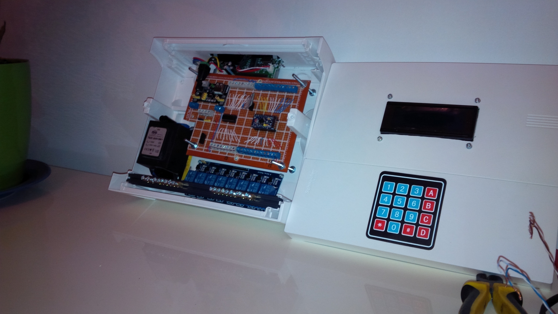
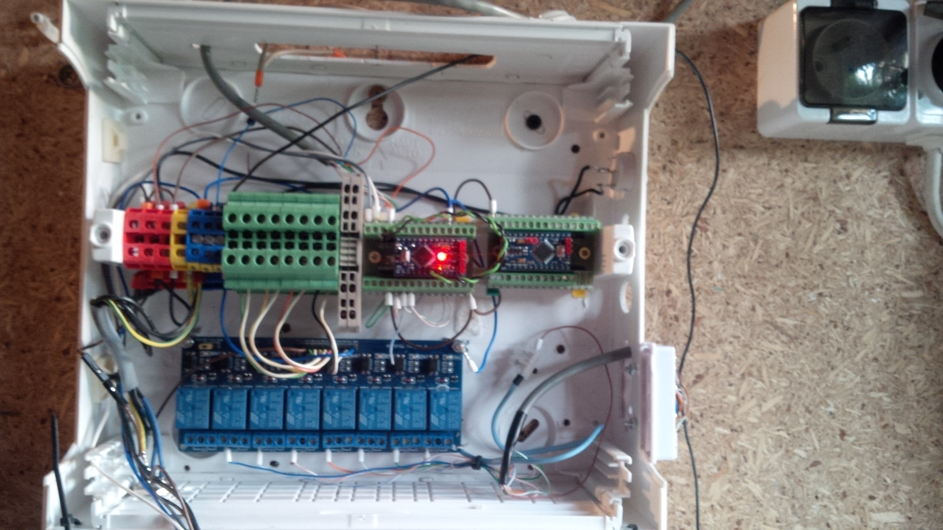
and some pictures of generation 3, which is under construct :)
Power supply:
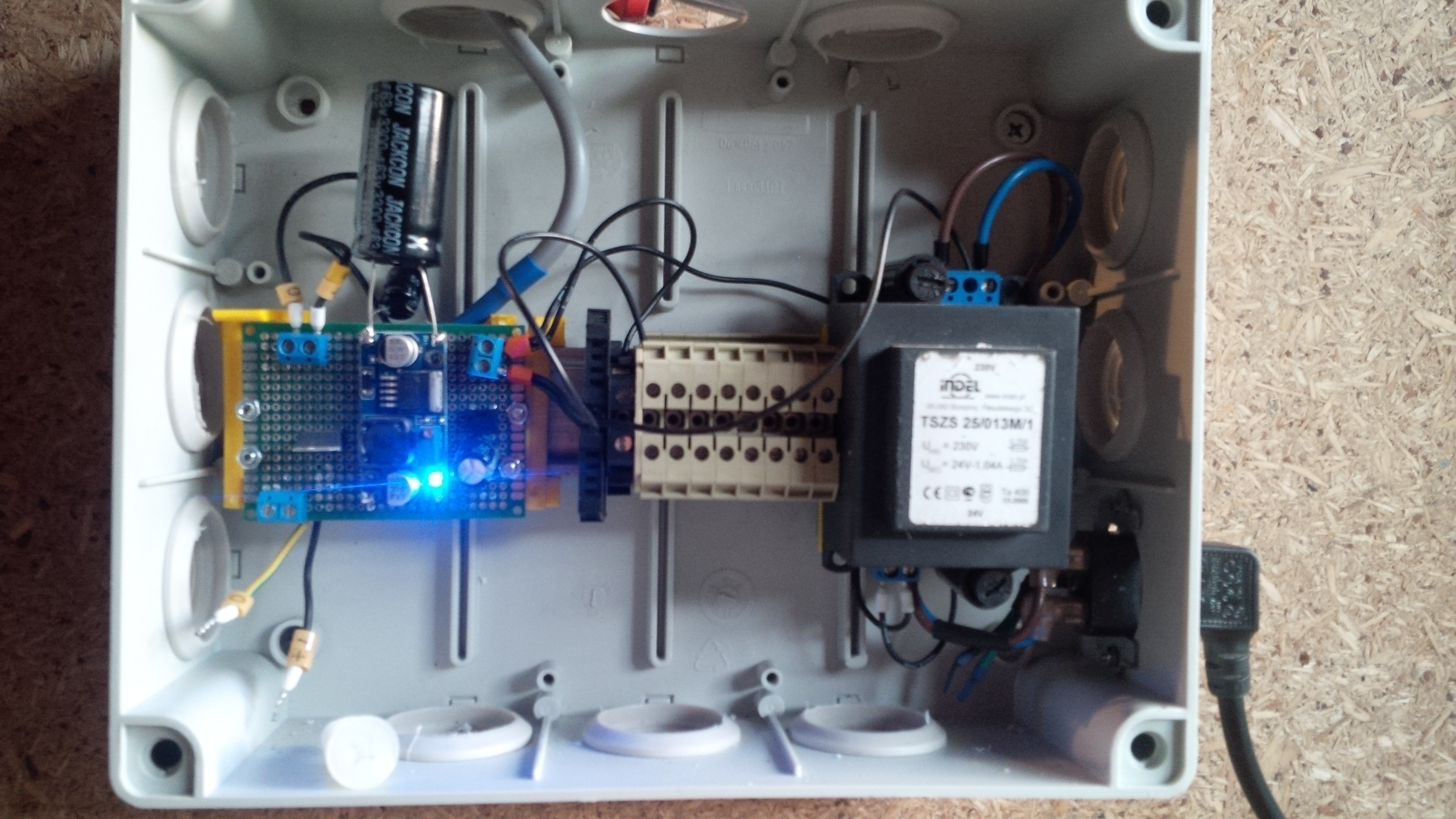
and control box with 2 ProMinis:
-
@karl261
Thanks,
in case I2C yes, and no.
with 1st generation [with 1 ProMini] I used I2C port expander PCF8574.
with 2nd generation [with MEGA2560] just pins, 8 pins, declared like this:/**** Kepad settings /
const byte ROWS = 4;
const byte COLS = 4;
char keys[ROWS][COLS] = {
{'1', '2', '3', 'A'},
{'4', '5', '6', 'B'},
{'7', '8', '9', 'C'},
{'', '0', '#', 'D'}
};byte rowPins[ROWS] = {47, 45, 43, 41};
byte colPins[COLS] = {39, 37, 35, 33};
int i2caddress = 0x20;
Keypad_I2C kpd = Keypad_I2C( makeKeymap(keys), rowPins, colPins, ROWS, COLS, i2caddress );with 3rd generation - plan to have 2nd ProMini with PCF expander.
attached library I use.
0_1474294070076_Keypad_I2C.zip
and some pictures of generation 3, which is under construct :)
Power supply:
and control box with 2 ProMinis:
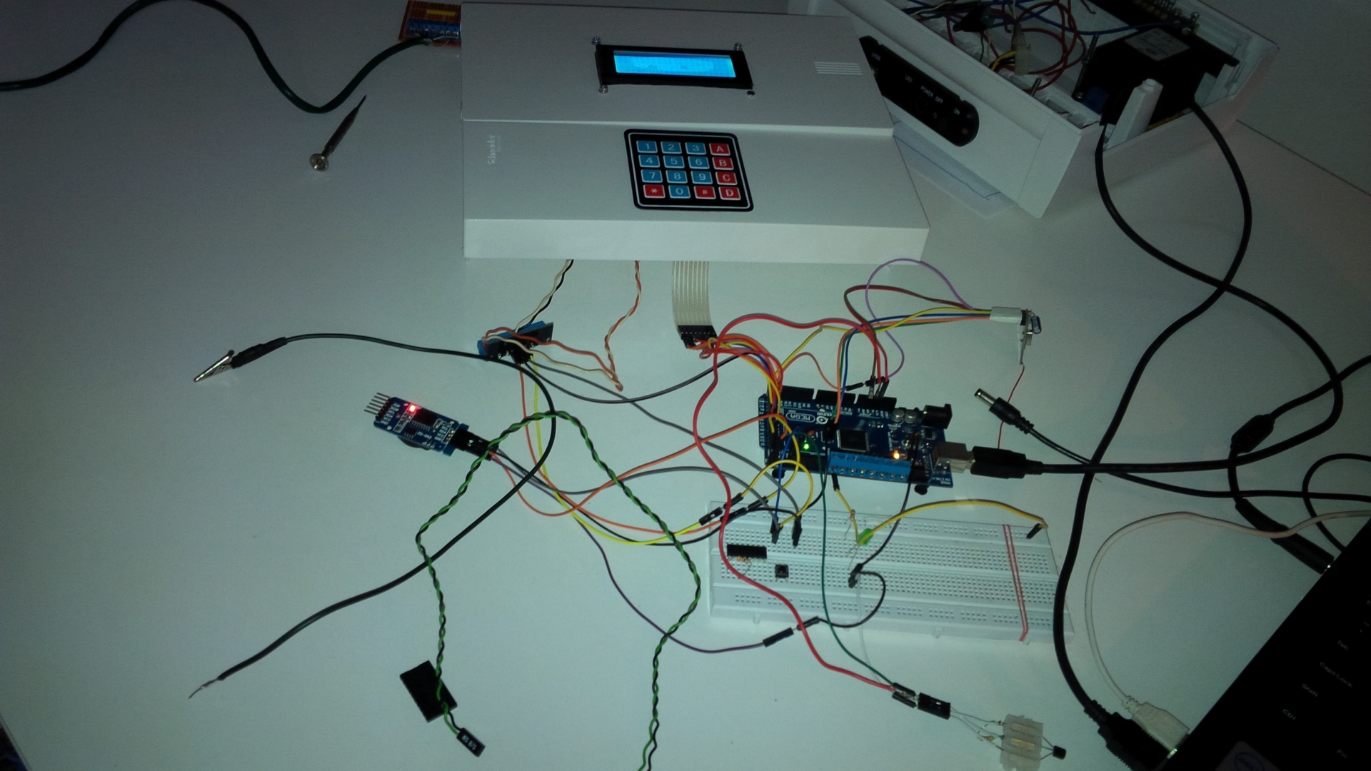
@marekd Thanks for the detailed reply. What the monster capacitor for in gen 3?
I plan to build my keypad with one pro mini and the PCF8574. Like your gen 1 & 3. How did / are you planning to wire the PCF8574? It seems rather straight forward according to this:
https://www.hackster.io/venkatesh_rao/i2c-keypad-73a012
Is this the wiring you are using? Or is it different?
Since I am building a battery keypad, I was also planning to use the interrupt line of the PCF8574.
-
@marekd Thanks for the detailed reply. What the monster capacitor for in gen 3?
I plan to build my keypad with one pro mini and the PCF8574. Like your gen 1 & 3. How did / are you planning to wire the PCF8574? It seems rather straight forward according to this:
https://www.hackster.io/venkatesh_rao/i2c-keypad-73a012
Is this the wiring you are using? Or is it different?
Since I am building a battery keypad, I was also planning to use the interrupt line of the PCF8574.
Hello! It looks like you're interested in this conversation, but you don't have an account yet.
Getting fed up of having to scroll through the same posts each visit? When you register for an account, you'll always come back to exactly where you were before, and choose to be notified of new replies (either via email, or push notification). You'll also be able to save bookmarks and upvote posts to show your appreciation to other community members.
With your input, this post could be even better 💗
Register Login