Slim Node as a Mini 2AA Battery PIR Motion Sensor
-
Hello,
I've successfuly uploaded these sketch to my Atmega328p. It works fine. Two things I want add:- I have changed the speed in the file MyConfig_h -> #define BAUD_RATE 9600 (otherwise I got nothing at the serial output)
- The sensor sends an 1 on "motion". How can I send an 0 on "no Motion" after 20sec? (low on data pin?)
Thank you
Hello !
@Tom71 Had you had the bigger PIR sensor, you could have adapted the delay manually, but it seems this smaller device doesn't offer that possibility. But I think you could wake up the node on a "CHANGE" interrupt instead of only "RISING" as in the example. For this PIR, it would happen approx 8s after last movement detection. Maybe you could add a 12s sleep phase before sending the zero ?
@m26872 I've read somewhere that a short distance between the nrf24l01 and the motion sensor could lead to perturbations, and I wonder if you've tested a bigger separation between them and also got those false trips ? They are very close to each other on your example, which makes me wonder.
Mikael
-
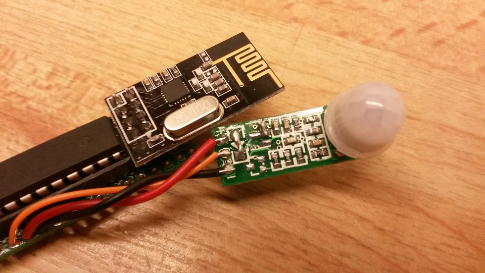
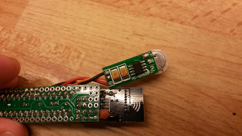
After reading about @AWI 's C123A battery based slim PIR sensor, I've finally have had time to play with the mini PIR motion sensor a little myself. Luckily I found a little for me easier, working design which I believe will satisfy my own needs sufficiently. It's basically just the mini-PIR HC-SR505 with its diode and voltage regulator removed, attached to the Slim Node and with simple but suitable sketch.
Conclusion from my playing with the HC-SR505 was
- power consumption was identical to mesurements by AWI, 46uA (no movement) and 62uA (movement) . Removing the 7133-regulator did not affect anything significantly due to its very low quiescent current (see datasheet, perhaps useful in some other project?)
- it's flexible regarding output (load) impedance and load will not affect sensitivity, no need for pull-up/down, filter, etc
- the supply voltage range with diode and 7133-regulator removed was great. Flawless results with only one AA (1.6V), and I saw no point to go lower.
- it's very supply noise sensitive and will false trigger on almost anything. Any kind of switching boost (voltage step-up) regulator made it trip continuously. (Found some differences between small and big 3.3V-step-ups btw). Any activity on a nRF connected to same supply would also generate a false trip.
- the ~3m max range or sensitivity doesn't seem to be affected by voltage level or noise.
I'm not going to try some hw-filter to get rid of the nRF false trip issue. I think we're all aware of the very hard task to to this when it comes to the nRF itself. For my need it's good enough to just dealing with it in the sketch.
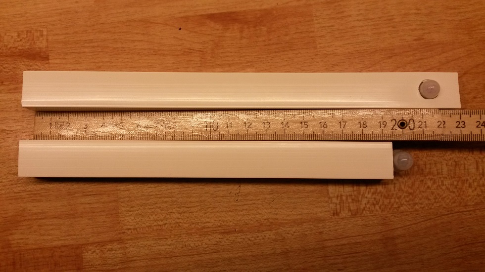
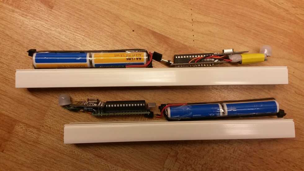
Two sensor nodes, one shorter enclosure with the PIR peeking out and the other one with a traditional oriented fit. I resoldered one of the three PIR legs so they're all on the same board side to facilitate the angled position.
The sketch
The sketch (and this sensor) is not intended to reside in a busy place or work as presence sensor. It's better as a guard, alarm or notification in a low frequency/activity environment. One obvious reason is that the range is not very impressive (max 3m). Then, with this sketch, the controller will just be informed when motion starts. After that, there's no way for it to distinguish absent motion from continuous motion. My reasons for this are (1) it's ok for my application (2) simple (3) save battery and (4) to overcome the false trip problem./** * EgSlimReed2 * Sketch for Slim Node and HC-SR505 based motion sensor. * Inspired by: * - MySensors motion sensor example: http://www.mysensors.org/build/motion * - AWI's CR123A based Slim Node motion sensor: http://forum.mysensors.org/topic/2478/slim-cr123a-2aa-battery-node * * Created by m26872 * Documentation: http://forum.mysensors.org... * * This program is free software; you can redistribute it and/or * modify it under the terms of the GNU General Public License * version 2 as published by the Free Software Foundation. * ******************************* * * REVISION HISTORY * Version 1.0 - Test to if node can operate in some way dealing with the Pir extreme sensitivity to noise on Vcc. * Version 2.0 - First "production node". "Inactivity day counter" introduced. * * DESCRIPTION * This sketch will only send trips as "1" to the controller. It's up to the controller to deal with the info. * The motion node will not notify controller when resets back to low state and is ready for a new trip. In reality * this is ~10s. And EVEN IF motion is detected continuously, there will be no new trip until motion has stopped for ~10s. * The HC-SR505 is very noise sensitive and will trigger spuriously for almost any activity * on Vcc (test thoroughly). To run the HC-505 at low voltages (tested flawlessly down to 1.6V), * the 7133-reg and diode are removed (and possibly increase the sensitivity even further). * Solution is to deal with it by interrupt type, check which source, block by sleep time etc. * * HC-505 output connects to MOTION_INPUT_PIN (here D3) without any supporting component. Input pull-up disabled. * Every 24 hrs without trip, increments a counter and after "BATTERY_REPORT_DAY" counts a battery report will be sent as a heartbeat signal. * Else a battery report will be sent after every "BATTERY_REPORT_BY_IRT_CYCLE" motion trips. * */ #include <MySensor.h> #include <SPI.h> #include <Vcc.h> //#define DEBUG #define NODE_ID 14 // Use static Node_ID <<<<<<<<<<<<<<<<<<<<<<<<<<<<<<<<<<<<<<<<<<<<<<< //14 var senaste "slim-PIR"-id #define SKETCH_NAME "EgSlimPIR2" #define SKETCH_VERSION "2.0 2016-01-01" #define CHILD_ID 5 #define MOTION_INPUT_PIN 3 #define BATTERY_REPORT_DAY 2 // Desired heartbeat(battery report) interval when inactive. #define BATTERY_REPORT_BY_IRT_CYCLE 10 // Make a battery report after this many trips. Maximum report interval will also be equal to this number of days. #define ONE_DAY_SLEEP_TIME 86400000 #define VCC_MIN 1.9 #define VCC_MAX 3.3 #ifdef DEBUG #define DEBUG_SERIAL(x) Serial.begin(x) #define DEBUG_PRINT(x) Serial.print(x) #define DEBUG_PRINTLN(x) Serial.println(x) #else #define DEBUG_SERIAL(x) #define DEBUG_PRINT(x) #define DEBUG_PRINTLN(x) #endif int dayCounter = BATTERY_REPORT_DAY; int irtCounter = 0; bool interruptReturn = false; // "false" will make the first loop disregard high output from HV-505 (from start-up) and make a battery report instead. Vcc vcc; MySensor gw; MyMessage msg(CHILD_ID, V_TRIPPED); void setup() { DEBUG_SERIAL(9600); DEBUG_PRINTLN(("Serial started")); delay(100); // to settle power for radio gw.begin(NULL,NODE_ID); pinMode(MOTION_INPUT_PIN, INPUT); digitalWrite(MOTION_INPUT_PIN, LOW); // Disable internal pull-ups gw.sendSketchInfo(SKETCH_NAME, SKETCH_VERSION); gw.present(CHILD_ID, S_MOTION); DEBUG_PRINTLN("Warming and blocking PIR trip for 20s."); gw.sleep(20000); // Wait until HC-505 warmed-up and output returned low. } void loop() { if (interruptReturn) { // Woke up by rising pin gw.send(msg.set("1")); // Just send trip (set) commands to controller. (Let controller reset and decide what to do with it.) irtCounter++; if (irtCounter>=BATTERY_REPORT_BY_IRT_CYCLE) { irtCounter=0; sendBatteryReport(); } } else { // Woke up by timer (or it's the first run) dayCounter++; if (dayCounter >= BATTERY_REPORT_DAY) { dayCounter = 0; sendBatteryReport(); } } gw.sleep(3000); // Make sure everything is stable before start to sleep with interrupts. (don't use "gw.wait()" here). Tests shows false trip ~2s after battery report otherwise. // Sleep until interrupt comes in on motion sensor or sleep time passed. interruptReturn = gw.sleep(MOTION_INPUT_PIN-2,RISING, ONE_DAY_SLEEP_TIME); // DEBUG_PRINT("interruptReturn: ");DEBUG_PRINTLN(interruptReturn); } void sendBatteryReport() { float p = vcc.Read_Perc(VCC_MIN, VCC_MAX, true); int batteryPcnt = static_cast<int>(p); gw.sendBatteryLevel(batteryPcnt); }Future development
In future sketch versions an idea is to let the sensor ask my controller when to arm or to disarm. Maybe hourly or with a controller set next sleep time duration. This will be combined with a digital-out pin controlled supply of the HC-SR505 to save the 47uA. Necessary warm-up and false trip blocking and will hopefully be mastered without side effects.Power economy
Idling current 52uA of this PIR motion sensor node is ok, but I'm worried about sending to frequent messages. Especially since I also want some kind of heartbeat for the longer motionless durations. Just to give me perspective I set up the two PIRs to cover the busiest areas in my home for 4 days, busier than usual due to holidays and guests. This produced 1765 messages (9% being battery reports) which is 220 messages/day/sensor. (For a normal weekday the figure was <100.)
Compare this with my reference Node 105 with ~100uA sleep mode current, 130 messages/day and for which my (today) guess is that it will survive on it's batteries for about 24 months (I know it theoretically doubtful, but the 100uA is probably lower).
My conclusion is that it's ok to use this PIR motion sensor as it is. The test setup was rather conservative and with a little more thought about how and where to place them, it could be improved.
I buy 40 AA batteries for the price of one rechargeable CR123A. But sure, the size becomes more attractive with a CR123A.Some more photos

-
Hello !
@Tom71 Had you had the bigger PIR sensor, you could have adapted the delay manually, but it seems this smaller device doesn't offer that possibility. But I think you could wake up the node on a "CHANGE" interrupt instead of only "RISING" as in the example. For this PIR, it would happen approx 8s after last movement detection. Maybe you could add a 12s sleep phase before sending the zero ?
@m26872 I've read somewhere that a short distance between the nrf24l01 and the motion sensor could lead to perturbations, and I wonder if you've tested a bigger separation between them and also got those false trips ? They are very close to each other on your example, which makes me wonder.
Mikael
@Mikael-Kermorgant said:
Maybe you could add a 12s sleep phase before sending the zero ?
Yes, but keep in mind that sending of "0" will also trig a new false motion signal, so sleep for another >8s before sleep with interrupt.
if you've tested a bigger separation between them and also got those false trips ?
Yes, when I breadboarded this setup, I had them approx. 10cm apart with exactly the same behaviour. I also did test with supply from different boosters (and only LED-resistor as load on motion output). Similar separation and no nRF, all together lead to my conclusion.
-
-
Hi guys,
I am wondering, if it wouldn´t be a good idea to use the PinChangeInt Library to wake the arduino from sleep by pin change interrupts. Wouldn´t this be the most power efficient variant? Or did I understand sth. wrong with the pin change interrupts? Thanks for your help in advance!!
-
I have build a small sensor platform and I am currently running it off of a CR2032 coin cell (small and cheap). I used the same motion sensor as in this thread to build a motion detector. Everything seems to work fine until the voltage drops below ~2.8V, then it starts to trigger constantly. I guess the problem is the low voltage.
Has anyone found a working setup with a low(er) voltage? Or successfully used a boost converter with a pir (creates false positives as well for me, although I will try that later too).Otherwise I would have to use 2xaa (too big) or CR123A (still kinda big and not very cheap) too ;(
@LastSamurai Since I tested it ok down to 1.6V with one AA, I have a feeling that the issue could be voltage stability rather than level. Maybe you could try two CR2032 in parallel ?
-
@LastSamurai Since I tested it ok down to 1.6V with one AA, I have a feeling that the issue could be voltage stability rather than level. Maybe you could try two CR2032 in parallel ?
@m26872 Great idea, that might help. I am currently trying out another battery, and if that doesn't work I will try 2 in parallel.
-
@m26872, am I understanding correctly that you did not need to step the voltage up to 5v in order to use this PIR sensor? If that's correct, do you know if the HC-SR505 works the same way? I will probably buy some of these smaller ones, but I have HC-SR505s on hand right now and would want to try it soon.
@JonnyDev13 This IS the HC-SR505 (5V Mini PIR). With the voltage regulator and diode removed.
Did you mean that you have the larger HC-SR501 ? In that case I don't know. I only remember that you'll need to remove the v-reg and diode in the same way to make it run on 3.3V. And I think @bjornhallberg reported successful results from longterm use of a batterypowered outdoor one.
-
@JonnyDev13 This IS the HC-SR505 (5V Mini PIR). With the voltage regulator and diode removed.
Did you mean that you have the larger HC-SR501 ? In that case I don't know. I only remember that you'll need to remove the v-reg and diode in the same way to make it run on 3.3V. And I think @bjornhallberg reported successful results from longterm use of a batterypowered outdoor one.
@m26872, yes you are correct. I have the larger ones. I must have copied and pasted the wrong part number. Thanks for the quick response. That's helpful information!
-
Hello everybody,
I´m struggeling with getting this sensor
to work.
The node registers with the GW, but doesnt submit the tripped reading.
Not even a permanent on or something. Just nothing. So i dont know how to troubleshoot here.
The PIR HC-SR505 is functional. I tested it with a testscript on a UNO.
And the 2AA Slimnode is functional as well. When using the node as a binary switch it works perfectly fine,
Just the combination 2AA Slimnode and HC-SR505 doesnt work.Anybody has an idea ?
Thanks in advance Komaandy
@Komaandy how are you powering the circuit?
The pir sensor is very sensitive to power fluctuations and not suited for below 3v. Also for 3v you need to "modify" the sensors power circuit. You should be able to find a lot of information when searching for the sensor. -
@ awi, so i desolderd and bridged the two mentioned components, and with the standard " Motion Detector " sketch it transmits tripped readings now :)
I power the circuit via a UNO ( 3,3Volt) or via 2 AA batterys ( 3,1 Volts -> meassured via multimeter)but when using the given sketch in this thread only battery readings are transmitted...
KR
Komaandy
-
Hello, when running the "Motion Detector sketch from the mysensors-examples" on these nodes with the 1Mhz bootloader with 2aa batteries some nodes freeze after appr. 24h .
Some continue working, i cant find the problem.
Does anybody have a idea what could cause those freezes ?
Thanks in advance -
Hello, when running the "Motion Detector sketch from the mysensors-examples" on these nodes with the 1Mhz bootloader with 2aa batteries some nodes freeze after appr. 24h .
Some continue working, i cant find the problem.
Does anybody have a idea what could cause those freezes ?
Thanks in advance -
@m26872 Thanks for your answer and thanks for this superb node :) :)
No, i didnt put the additional sleep in , where should I put this ? Im a little confused.../** * The MySensors Arduino library handles the wireless radio link and protocol * between your home built sensors/actuators and HA controller of choice. * The sensors forms a self healing radio network with optional repeaters. Each * repeater and gateway builds a routing tables in EEPROM which keeps track of the * network topology allowing messages to be routed to nodes. * * Created by Henrik Ekblad <henrik.ekblad@mysensors.org> * Copyright (C) 2013-2015 Sensnology AB * Full contributor list: https://github.com/mysensors/Arduino/graphs/contributors * * Documentation: http://www.mysensors.org * Support Forum: http://forum.mysensors.org * * This program is free software; you can redistribute it and/or * modify it under the terms of the GNU General Public License * version 2 as published by the Free Software Foundation. * ******************************* * * REVISION HISTORY * Version 1.0 - Henrik Ekblad * * DESCRIPTION * Motion Sensor example using HC-SR501 * http://www.mysensors.org/build/motion * */ // Enable debug prints // #define MY_DEBUG // Enable and select radio type attached #define MY_RADIO_NRF24 //#define MY_RADIO_RFM69 #include <MySensors.h> unsigned long SLEEP_TIME = 120000; // Sleep time between reports (in milliseconds) #define DIGITAL_INPUT_SENSOR 3 // The digital input you attached your motion sensor. (Only 2 and 3 generates interrupt!) #define CHILD_ID 1 // Id of the sensor child // Initialize motion message MyMessage msg(CHILD_ID, V_TRIPPED); void setup() { pinMode(DIGITAL_INPUT_SENSOR, INPUT); // sets the motion sensor digital pin as input } void presentation() { // Send the sketch version information to the gateway and Controller sendSketchInfo("Motion Sensor", "1.0"); // Register all sensors to gw (they will be created as child devices) present(CHILD_ID, S_MOTION); } void loop() { // Read digital motion value bool tripped = digitalRead(DIGITAL_INPUT_SENSOR) == HIGH; Serial.println(tripped); send(msg.set(tripped?"1":"0")); // Send tripped value to gw // Sleep until interrupt comes in on motion sensor. Send update every two minute. sleep(digitalPinToInterrupt(DIGITAL_INPUT_SENSOR), CHANGE, SLEEP_TIME); }``` -
@m26872 Thanks for your answer and thanks for this superb node :) :)
No, i didnt put the additional sleep in , where should I put this ? Im a little confused.../** * The MySensors Arduino library handles the wireless radio link and protocol * between your home built sensors/actuators and HA controller of choice. * The sensors forms a self healing radio network with optional repeaters. Each * repeater and gateway builds a routing tables in EEPROM which keeps track of the * network topology allowing messages to be routed to nodes. * * Created by Henrik Ekblad <henrik.ekblad@mysensors.org> * Copyright (C) 2013-2015 Sensnology AB * Full contributor list: https://github.com/mysensors/Arduino/graphs/contributors * * Documentation: http://www.mysensors.org * Support Forum: http://forum.mysensors.org * * This program is free software; you can redistribute it and/or * modify it under the terms of the GNU General Public License * version 2 as published by the Free Software Foundation. * ******************************* * * REVISION HISTORY * Version 1.0 - Henrik Ekblad * * DESCRIPTION * Motion Sensor example using HC-SR501 * http://www.mysensors.org/build/motion * */ // Enable debug prints // #define MY_DEBUG // Enable and select radio type attached #define MY_RADIO_NRF24 //#define MY_RADIO_RFM69 #include <MySensors.h> unsigned long SLEEP_TIME = 120000; // Sleep time between reports (in milliseconds) #define DIGITAL_INPUT_SENSOR 3 // The digital input you attached your motion sensor. (Only 2 and 3 generates interrupt!) #define CHILD_ID 1 // Id of the sensor child // Initialize motion message MyMessage msg(CHILD_ID, V_TRIPPED); void setup() { pinMode(DIGITAL_INPUT_SENSOR, INPUT); // sets the motion sensor digital pin as input } void presentation() { // Send the sketch version information to the gateway and Controller sendSketchInfo("Motion Sensor", "1.0"); // Register all sensors to gw (they will be created as child devices) present(CHILD_ID, S_MOTION); } void loop() { // Read digital motion value bool tripped = digitalRead(DIGITAL_INPUT_SENSOR) == HIGH; Serial.println(tripped); send(msg.set(tripped?"1":"0")); // Send tripped value to gw // Sleep until interrupt comes in on motion sensor. Send update every two minute. sleep(digitalPinToInterrupt(DIGITAL_INPUT_SENSOR), CHANGE, SLEEP_TIME); }```@Komaandy said in Slim Node as a Mini 2AA Battery PIR Motion Sensor:
I meant like this (look in code below), but it's just a wild guess.
/** * The MySensors Arduino library handles the wireless radio link and protocol * between your home built sensors/actuators and HA controller of choice. * The sensors forms a self healing radio network with optional repeaters. Each * repeater and gateway builds a routing tables in EEPROM which keeps track of the * network topology allowing messages to be routed to nodes. * * Created by Henrik Ekblad <henrik.ekblad@mysensors.org> * Copyright (C) 2013-2015 Sensnology AB * Full contributor list: https://github.com/mysensors/Arduino/graphs/contributors * * Documentation: http://www.mysensors.org * Support Forum: http://forum.mysensors.org * * This program is free software; you can redistribute it and/or * modify it under the terms of the GNU General Public License * version 2 as published by the Free Software Foundation. * ******************************* * * REVISION HISTORY * Version 1.0 - Henrik Ekblad * * DESCRIPTION * Motion Sensor example using HC-SR501 * http://www.mysensors.org/build/motion * */ // Enable debug prints // #define MY_DEBUG // Enable and select radio type attached #define MY_RADIO_NRF24 //#define MY_RADIO_RFM69 #include <MySensors.h> unsigned long SLEEP_TIME = 120000; // Sleep time between reports (in milliseconds) #define DIGITAL_INPUT_SENSOR 3 // The digital input you attached your motion sensor. (Only 2 and 3 generates interrupt!) #define CHILD_ID 1 // Id of the sensor child // Initialize motion message MyMessage msg(CHILD_ID, V_TRIPPED); void setup() { pinMode(DIGITAL_INPUT_SENSOR, INPUT); // sets the motion sensor digital pin as input } void presentation() { // Send the sketch version information to the gateway and Controller sendSketchInfo("Motion Sensor", "1.0"); // Register all sensors to gw (they will be created as child devices) present(CHILD_ID, S_MOTION); } void loop() { // Read digital motion value bool tripped = digitalRead(DIGITAL_INPUT_SENSOR) == HIGH; Serial.println(tripped); send(msg.set(tripped?"1":"0")); // Send tripped value to gw sleep(3000); // Sleep 3s to make sure everything is stable before we start to sleep with interrupts. // Sleep until interrupt comes in on motion sensor. Send update every two minute. sleep(digitalPinToInterrupt(DIGITAL_INPUT_SENSOR), CHANGE, SLEEP_TIME); }``` -
@m26872 said in Slim Node as a Mini 2AA Battery PIR Motion Sensor:
Removing the 7133-regulator did not affect anything significantly due to its very low quiescent current (see datasheet, perhaps useful in some other project?)
ok, does that mean one does not have to remove the voltage regulator and the diode? @AWI is saying one must modify the PIR and now I am irritated...
Hello! It looks like you're interested in this conversation, but you don't have an account yet.
Getting fed up of having to scroll through the same posts each visit? When you register for an account, you'll always come back to exactly where you were before, and choose to be notified of new replies (either via email, or push notification). You'll also be able to save bookmarks and upvote posts to show your appreciation to other community members.
With your input, this post could be even better 💗
Register Login