Scene Controller


  • Admin


  • looks awesome!


  • Hero Member

    Sweet! Now I don't feel like pasting any pictures of my scene controller anymore.


  • Very nice


  • Contest Winner

    It's a thing!


  • @hek said:

    Here comes a little preview of the upcoming touch display scene controller example.

    Hope to finalize a little youtube clip before the release.
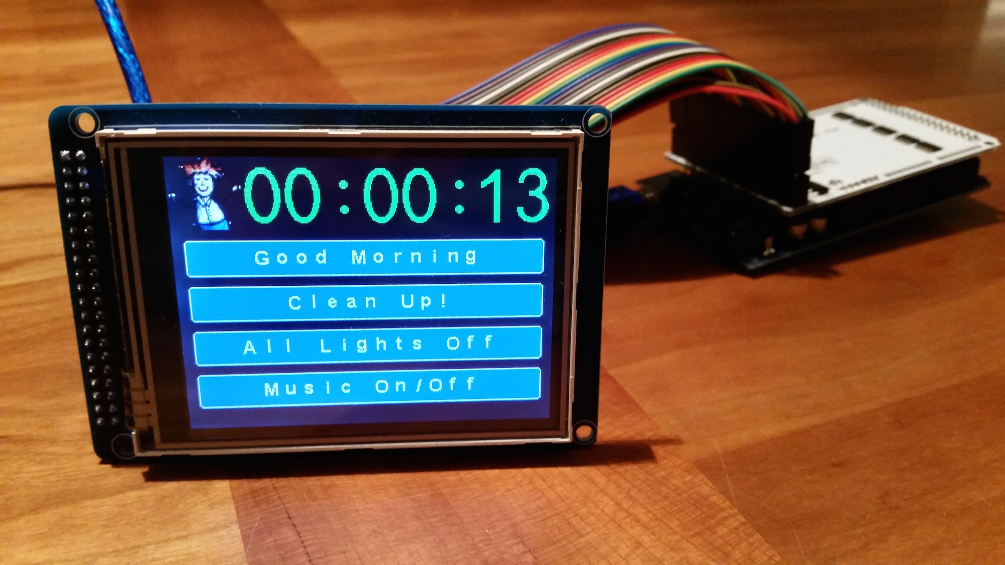
    scenecontroller.jpg

    Wow, was this started only when I mentioned it? Because if so, kudos on the quick turn around! Looks great! You as well, @korttoma , what's yours like??

    Do you need a pen to touch the buttons or are your fingers okay?

    Does it seem pretty accurate (how many buttons could you cram on that screen)?

    I'm wondering if its worth putting some serious time in to print a nice body and get a rechargeable LiIon and a charging dock, or if its just simpler to get a cheap android tablet or something.


  • Hero Member

    @hek
    Fantastic Hek! You just keep amazing us!

    Can you turn on/off/dim the LCD but keep the touch enabled? Im sure the answer is yes, but just asking for sure.

    For night time you'd likely want the screen to dim to 5% and wake up when user touches? Perhaps add a light sensor..or just do this based of the time of day...

    Whilst i love the Imperihome interface, using these on some wallplates would be equally cool!


  • Admin

    @naveen said:

    Do you need a pen to touch the buttons or are your fingers okay?

    FIngers works great.

    Does it seem pretty accurate (how many buttons could you cram on that screen)?

    Depends a bit on screen orientation. If you use short texts you could add dual columns (not supported). And maybe squeeze in another row (the sketch adopts button height after the number of buttons).

    I'm wondering if its worth putting some serious time in to print a nice body and get a rechargeable LiIon and a charging dock, or if its just simpler to get a cheap android tablet or something.

    Oh.. so intent to use it as a carry around remote? I have no idea how long the batteries would last. I was more thinking of permanently install it somewhere on a wall with power.

    Can you turn on/off/dim the LCD but keep the touch enabled? Im sure the answer is yes, but just asking for sure.

    Yes.

    For night time you'd likely want the screen to dim to 5% and wake up when user touches? Perhaps add a light sensor..or just do this based of the time of day...

    Based on time would probably be easiest option here. This has not been implemented yet though.

    I still need to add some deboucing to avoid multiple sends when user touches a button. The touch function sometimes report multiple touches sometimes.

    HELP: When connecting radio yesterday I ran into some troubles getting radio to initialize when sharing SPI with screen/touch/SD card reader on the display.
    Do we have any SPI experts around?


  • Admin

    Maybe SoftSPI would be an option.

    Created an issue over at TMRh20's RF24 fork.
    https://github.com/TMRh20/RF24/issues/24

    Has Anyone actually gotten W5100 ethernet module woking with MySensors?
    http://shanes.net/how-to-use-an-nrf24l01-rf24-with-an-arduino-ethernet-shield/


  • Contest Winner

    I will dig around some with mixing W5100 and RF24 sometime next week. I believe using soft SPI for RF24 is the answer due to the fact that many reports that W5100 is misusing the SPI bus (and the library uses the HW SPI block).
    I have verified that W5100 module is working using a simple webserver on my Nano, so if it can keep the SPI bus for itself it is happy.
    I do not like it, but since I already got one W5100 and only intend to use it for my gateway, I can live with customizing the RF24 implementation to use software SPI in this case.


  • my w5100 shield was giving me trouble when trying to use it with the rf24. check wires error. Will try soft spi today and see if I can get it working.


  • Admin

    @Rek

    Yep, check out the github issue above. TMRh20 has already created a branch for us to test.


  • Hero Member

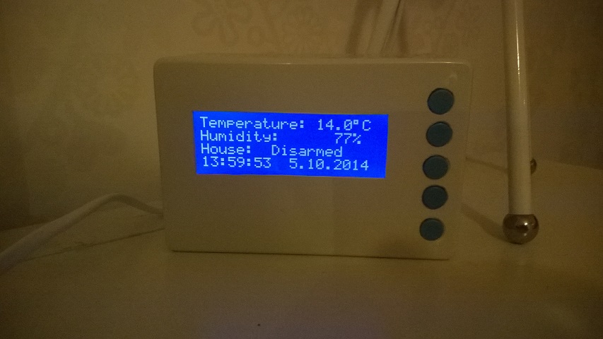
    @naveen said:

    @korttoma , what's yours like??

    WP_20141005_005.jpg

    The picture is a little dark but you get the idea. White box with blue buttons.


  • Contest Winner

    nice job thomas!


  • @korttoma Hey, that looks good! Where did you get the enclosure?


  • Hero Member

    @Nuubi from a local electronics shop

    the producer of the box seems to be Hammond Manufacturing maybe your local supplier have the same box 😉


  • Hero Member

    @BulldogLowell said:

    nice job thomas!

    Thanks Jim, btw I figured out a neet way to dim the backlight using just a resistor and a transistor. On the I2C LCD driver board there is a jumper for the backlight and I just connected the transistor to these 2 pins and the gate via a 10kR to a PWM pin. Works great.

    Also I want to thank you Jim again cause I started from your weather station scene controller and ended up with this:

    https://codebender.cc/sketch:44676


  • Admin

    Finally got around wrapping this up. Hope to provide a youtube demo clip in the coming days. But everything is checked in on github.

    Used the following touch screen when creating the example.

    https://codebender.cc/sketch:54953


  • Hero Member

    Hi Hek - Can you advise what the physical size of the LCD pcb is?

    I have a really nice bamboo box that my wifes sunglasses came in ( image here) and this might be an ideal case for it!
    http://www.pinterest.com/pin/201958364513700248/

    ( imho...the box is nicer than her sunglasses ( which are now broken anyway )


  • Admin

    10x6.5 (cm)
    Stacked height about 3.2 cm (2650+shield+display)


  • Admin

    First post updated with youtube clip and a link to the build page.


  • Hero Member

    @hek thanks Hek


  • Hero Member

    @hek
    Man you are costing me a fortune... Now there's another project I will need to try.. 🙂

    Seriously though, very cool!


  • Will it be possible to use with 3.5 LCD instead of 3.2 ? Many differences for the code to make ?
    Because now we can find 3.5LCD directly connectable on 2560 and total is cheaper too.


  • Admin

    @lunarok

    It depends on if the display is supported by the UTFT library I used in the example.


  • Plugin Developer

    Very cool display, well done!


  • Hi,

    Can't use the sketch.
    From codebender include on mysensors it just say there was an error compiling it.
    When I clone it, directly on codebenders it say there was a communication error.
    When try with local IDE, there is a lot of errors about the time library

    This type (for each month and day)
    libraries/Time/DateStrings.cpp:18:18: error: variable ‘monthStr1’ must be const in order to be put into read-only section by means of ‘attribute((progmem))’
    char monthStr1[] PROGMEM = "January";


  • @hek : can you update the mysensors lib in codebenders ? On scene controller page you ask to modify SOFTSPI, it's not on codebenders (unless it makes a copy for me) but it is on git


  • Admin

    Codebender has a bug when library contains large files (UTFT in this case). This has been reported to them and they will fix it eventually. In the meantime I have just re-uploaded the libraries without these binary (pdf files). But I think they need to clear some caches before it actually compiles.

    Enabling SOFTSPI in the MySensors lib-config just for the SceneController is harder because we can only keep one version of the MySensors library at the time in our "repository" on codebender.

    Regarding the DateStrings compilation error .. I've just pushed an update which works in IDE 1.5.8 now.


  • Admin

    @hek
    Can't you define the SoftSPI settings in the sketch, before you load the library header file? (And then make some conditional defines in the library)

    (I admit, I don't know the arduino toolchain fully, so I could be mistaken here.. But in "normal" c/c++ compilers you can do it)

    Or is the libraries at codebender precompiled?


  • Admin

    Nope, it doesn't work in the crappy Arduino builder.

    And I thing codebender tries to simulate Arduino as much as possible.


  • SC.JPG

    Does this look right?

    I ask because i have installed tge scene controller
    But i cant understand how i will set up a scene with this


  • Admin

    Looks right.

    1. Cretate a scene (under Automation).
    2. Create new trigger on "Arduino ScheneCtrl 2:1"
    3. Choose the appropriate scene action

    Screen Shot 2014-11-24 at 15.04.19.png


  • I've been playing around with this quite a bit and have it working great. That said, I know I remember seeing a thread where cases (3D printed) were being discussed . However, I can't find the link.

    Anyone have it handy?


  • Still trying to find a case while tinkering and came up with another question.

    Has anyone figured out how to "toggle" a scene? I think it'd be cool to have it somehow know if a scene was active and if so run an "off" version of that scene. Likewise, if the scene is "off", run an "on" version.

    Maybe another way is to abandon the scene functionality altogether and just somehow control the zwave switch individually.

    Just thinking out loud.

    Very cool project.


  • Can i use Arduino Uno to make scene controller? If okie, please teach me to do it? thanks


  • Admin


  • Bringing back an old thread. As you can tell, I'm not much of a developer. ..... apologies....

    I'm updating all of my sensors to 1.5 but am having issues with this one. When I compile (using IDE 1.6.5) and a new libraries directory, I get the following error.

    Any ideas?

    
    TouchDisplaySceneControllerSensor:67: error: no matching function for call to 'MySensor::MySensor(int, int)'
    TouchDisplaySceneControllerSensor.ino:67:18: note: candidates are:
    In file included from TouchDisplaySceneControllerSensor.ino:37:0:
    C:\Users\tbully\Documents\Arduino\libraries\MySensors/MySensor.h:158:2: note: MySensor::MySensor(MyTransport&, MyHw&)
      MySensor(MyTransport &radio =*new MyTransportNRF24(), MyHw &hw=*new MyHwDriver()
      ^
    C:\Users\tbully\Documents\Arduino\libraries\MySensors/MySensor.h:158:2: note:   no known conversion for argument 1 from 'int' to 'MyTransport&'
    C:\Users\tbully\Documents\Arduino\libraries\MySensors/MySensor.h:149:7: note: MySensor::MySensor(const MySensor&)
     class MySensor
           ^
    C:\Users\tbully\Documents\Arduino\libraries\MySensors/MySensor.h:149:7: note:   candidate expects 1 argument, 2 provided
    no matching function for call to 'MySensor::MySensor(int, int)'
    

  • Hero Member

    @tbully It looks like you are using the "old" gw(pin,pin) call. This has been replaced with a separate initialisation for the radio. In case you use the default pin definitions gw(9,10) you can just replace gw(.., ..) ; by gw ;


  • Thanks @awi. I meant to come back and correct my post. I did see that after going back and looking at the old 1.4 API (you are correct). It has been many months since I've looked at this sketch. However, I'm not using the default PINs here so I guess I have to change MyConfig for this sketch?

    /**********************************
    *  NRF24L01 Driver Defaults
    ***********************************/
    #define RF24_CE_PIN		   9
    #define RF24_CS_PIN		   10


  • Hero Member

    @tbully The new API uses a separate radio class initiator Something like (from one of my own 'learnings' , Ceech board in this case)

    MyTransportNRF24 transport(7, 8); // Sensoduino (8,7) Ceech board, 3.3v (7,8)  (pin default 9,10)
    MySensor gw(transport);       


  • @awi , not surprisingly, this worked as expected.

    I changed the following in Hek's script and it worked fine:

    MyTransportNRF24 transport(17, 18);
    MySensor gw(transport);


  • Bringing back this old thread as I am building the scene controller now.
    I am having a problem with a lot of garbage like this:

    send: 7-7-0-0 s=255,c=3,t=15,pt=2,l=2,sg=0,st=ok:0
    send: 7-7-0-0 s=255,c=0,t=17,pt=0,l=5,sg=0,st=ok:1.5.2
    send: 7-7-0-0 s=255,c=3,t=6,pt=1,l=1,sg=0,st=ok:0
    read and drop: 7-7-0 s=255,c=3,t=6,pt=1,l=1,sg=0:0
    read and drop: 0-224-0 s=0,c=0,t=0,pt=0,l=0,sg=0:
    ver mismatch
    read and drop: 0-224-0 s=0,c=0,t=0,pt=0,l=0,sg=0:
    ver mismatch
    .....
    goes on and on
    

    I do not have different MySensors GW/nodes. All of my GW/Nodes have MYS 1.5.2 Where does ver mismatch come from? Also time is not getting pulled into the scene controller from the controller (Domoticz).
    Cannot get time from the controller either...


  • OK, just to revive this project, I decided to modify it as follows:

    0_1465644897970_2016-06-10 14.25.29.jpg

    This would make the transmitter fit between the screen and the adapter

    0_1465644955871_2016-06-10 14.25.53.jpg

    The problem is that this sandwich is super thick. So I got a new screen from itead studio, which can be used without the adapter. In this photo I desoldered D14-D21 pins as they are not used in order to hook up nrf24l01+:

    0_1465645049555_2016-06-10 14.26.45 HDR-2.jpg


  • This is a semi finished project. The power is fed via ICSP through 662k (under the red tape):

    0_1465645782812_2016-06-10 14.27.18.jpg

    Now I need to isolate everything:

    0_1465645826597_2016-06-11 12.05.59.jpg

    This is how Mega + the screen looks:

    0_1465645871949_2016-06-11 12.07.50.jpg

    0_1465645883516_2016-06-11 12.07.56.jpg

    Now I need to figure out how to stick the battery between the screen and Mega 🙂
    Any suggestions welcome!


  • Additionally, I have recently received a new Enhanced Nextion screen (again from Itead Studio) and a new ESP8266 PCB:

    0_1465645976276_2016-06-11 12.10.27.jpg

    0_1465645991137_2016-06-11 12.10.36.jpg

    Much thinner 🙂 so watch this space....


  • Hardware Contributor

    @alexsh1
    cool 😉 I made one like this some time ago https://forum.mysensors.org/topic/2766/an-esp8266-nextion-scene-controller/5
    but it's not with the new nextion rev. i like these hmi screens, easy to use.


  • @scalz Yeah, I saw your post a few months ago and it made me think seriously about getting my hands dirty with ESP8266. I have just started so do not expect to come up with anything fully working tomorrow as there are many peculiarities concerning ESP8266 from firmware to programming.

    You have fully finished integration of your thermostat/scene controller with the controller?
    Are you using Domoticz?


  • Hardware Contributor

    @alexsh1 i'm using mqtt and jeedom for this (jeedom has plugin for thermostat etc..) and i have another board which does energy monitoring+heater management. just for curiosity, i have enough pcb lol, but where did you buy your pcb for nextion? or maybe you did it?


  • @scalz I am not that smart yet to design my own boards. Having said that I have made a good progress on C++ and MySensors over a year. So designing my own PCB is a next logical step.
    The problem is that my home has been fully automated. I have to challenge myself with a more difficult projects or move on to automate my neighbours house lol 🙂
    The most difficult part though is finding the right case. Printing on 3D printer is not cheap as I do not have one and finding something of the shelf is literally impossible.

    Talking about the PCB, I took the one design by
    Peter and Aidan:

    http://tech.scargill.net/new-pcb/

    However, I'm redesigning the software part to make it a multi functioning scene controller for Domoticz.


  • A small teaser - quick menu. One has to be a graphic designer to get the menu nailed.

    0_1466201059540_image.jpg


  • This is still in an alpha state and ESP8266 development may take some time.

    This is a TFT screen with the daughter board:

    0_1466201111358_image.jpg


Log in to reply
 

Suggested Topics

  • 1
  • 3
  • 6
  • 3
  • 1
  • 6

97
Online

11.5k
Users

11.1k
Topics

112.7k
Posts