💬 Just RFM gateway
-
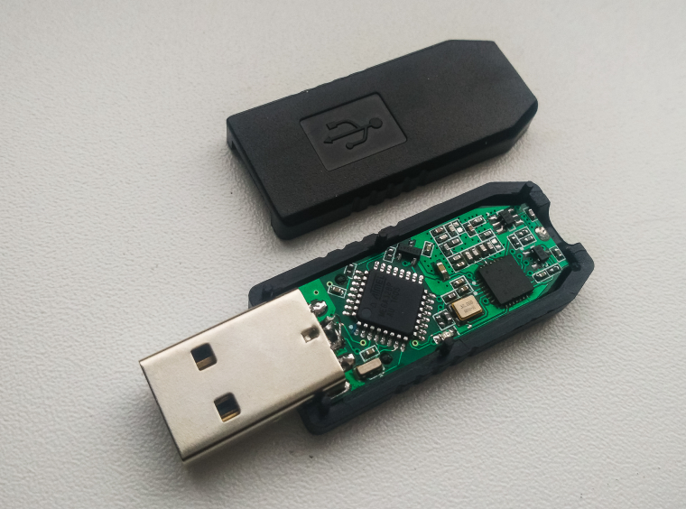
It appears to be one of the rare projects that doesn't use a pre-made radio module but instead does it's own radio from scratch on the PCB. That opens the door to overcoming some of the known shortcomings of, for example, the HopeRF modules.
-
Will you sell this one also?
@Cliff-Karlsson
Thanks for your attention to this project. Unfortunately I can't sell this board yet, I just designed it last night :) But many of my boards are under production now. May be those will be interesting for you too. I will show them as soon as they are produced and tested :stuck_out_tongue_winking_eye:
This board is relatively difficult to assemble and I'm not sure there is sense in producing it exactly in this variant. So I've shown it to get your feedback and make a decision about this project.@NeverDie
Can you list some of standard rfm modules shortcomings that you know? This board was designed strictly according to the reference design and manufacturer recommendations. -
@koresh as usual, looks very neat ;)
Just curious :blush:
- is it the high power circuit for rfm69H ?
- where do you get your usb box?
I did my gw a while now.. I don't know if it would fit in.. perhaps my sma connector (well i have a printer in case).
looks the same a bit to your! Are we connected ? :smile:
Mine is 32bits atsam though, radio module because i wanted it RFM69 or RFM95 (so RFM69HCW footprint). I also have an uid i2c eeprom, and love rgb led :) If it can give you inspi! I'll update my topic so if people want to play. I already tested rev1..Keep the good work, i'm always impressed :)
-
@koresh as usual, looks very neat ;)
Just curious :blush:
- is it the high power circuit for rfm69H ?
- where do you get your usb box?
I did my gw a while now.. I don't know if it would fit in.. perhaps my sma connector (well i have a printer in case).
looks the same a bit to your! Are we connected ? :smile:
Mine is 32bits atsam though, radio module because i wanted it RFM69 or RFM95 (so RFM69HCW footprint). I also have an uid i2c eeprom, and love rgb led :) If it can give you inspi! I'll update my topic so if people want to play. I already tested rev1..Keep the good work, i'm always impressed :)
@scalz
Thanks!
Oh. Your current version is perfect!Yes - it is high power version. So we have high power circuit and antenna switch to commutation it between transmitter and receiver.
You can find this case on aliexpress easy. The maximum width of the board is 14mm so I decided to try route rfm myself. About your pereferials... It's nice but I have no enough free space, because I'm using old widely popular cpu and onboard usb-ttl convertor requires space. So I decided to discard any additional functions.
-
i was sure, great work! i like your too :)
thx for precision ;)
yep atsam is native usb so no need of ttl converter, but need to burn the bootloader first through swd -
@Cliff-Karlsson
Thanks for your attention to this project. Unfortunately I can't sell this board yet, I just designed it last night :) But many of my boards are under production now. May be those will be interesting for you too. I will show them as soon as they are produced and tested :stuck_out_tongue_winking_eye:
This board is relatively difficult to assemble and I'm not sure there is sense in producing it exactly in this variant. So I've shown it to get your feedback and make a decision about this project.@NeverDie
Can you list some of standard rfm modules shortcomings that you know? This board was designed strictly according to the reference design and manufacturer recommendations.@Koresh said:
@NeverDie
Can you list some of standard rfm modules shortcomings that you know? This board was designed strictly according to the reference design and manufacturer recommendations.The two that I'm aware of are:
- The RF switch that HopeRF uses on the RFM69HW is, allegedly, only rated down to 2.4v instead of the 1.8v minimum voltage that the Semtech SX1231h chip supports.
- The RFM69HW can't cover the full Tx power range that, in theory, a proper implementation could. The RFM69HW's minimum Tx power is greater than for the RFM69W, and obviously the RFM69W's max Tx power is less than the RFM69HW. In theory, it should be possible for one module (or, in your case, radio on a PCB) to cover the entire range.
-
Great project! :+1: Can you share the scheme of your project? I want to
familiarize with your device more closely. -
If you have time maybe it is not so much more work to also release a similar sensor board? Like a sensebender with rfm radio
-
Great project! :+1: Can you share the scheme of your project? I want to
familiarize with your device more closely. -
If you have time maybe it is not so much more work to also release a similar sensor board? Like a sensebender with rfm radio
@Cliff-Karlsson See PM :smirk:
-
@Koresh said:
@NeverDie
Can you list some of standard rfm modules shortcomings that you know? This board was designed strictly according to the reference design and manufacturer recommendations.The two that I'm aware of are:
- The RF switch that HopeRF uses on the RFM69HW is, allegedly, only rated down to 2.4v instead of the 1.8v minimum voltage that the Semtech SX1231h chip supports.
- The RFM69HW can't cover the full Tx power range that, in theory, a proper implementation could. The RFM69HW's minimum Tx power is greater than for the RFM69W, and obviously the RFM69W's max Tx power is less than the RFM69HW. In theory, it should be possible for one module (or, in your case, radio on a PCB) to cover the entire range.
@NeverDie
Thanks for the known shortcomings. Some thoughts about solutions.- This board is not a battery device, but I'm sure it is possible to solve this problem for battery devices. I can't find a spdt switch with recommended control voltage lower than 3v (2.5v is absolute minimum). But all of them require very low control current. So it is possible to use charge-pump converters (inductorless) as 3.3-5v low power supply (controllable by a controller like REG710, so it is possible to shut it down). This power supply can be used to control spdt switch.
- Is this problem widespread? I can suppose it is caused by omitting some components in some modules.
-
It works! :smile:
Have uploaded some photos. Will share project sources soon :wink: -
@Koresh - woaw, RF PCB design - 4 layer or what do you use?
Via stitching for analog ground? How do you connect analog/digital groundplane together? F. Bead?
Man... so much to learn!
Please release the design... Im sure I have alot to learn from it. -
I'm also here for some design files to learn from. It looks awesome, not too sure how applicable it would be, how do you plan on utilising this, is the usb port there for data or just power? If it is data, are you having it connected to your home automation server constantly?
-
@Koresh - woaw, RF PCB design - 4 layer or what do you use?
Via stitching for analog ground? How do you connect analog/digital groundplane together? F. Bead?
Man... so much to learn!
Please release the design... Im sure I have alot to learn from it.@sundberg84 Do not worry. It's not a very difficult design. :wink: ATmega is a relatively slow chip (I mean slow edges) and we have not long high speed data lines. So we do not need impedance control production and it is just 2-layer board (I have experience in multilayer design but it's really not needed in this case ;)). RF69 chip has no separate analog ground and even in reference boards all gnd pins are connected directly. RF ground planes are just decoupled without ferrite beads but may be I will add them, not sure yet if they are needed.
@Samuel235 This board contains usb UART-TTL converter (CH340, see bottom layer of the board and schematic which I will upload soon) so of course you can use usb to connect gate to controller. I have been using this device only for one day today and I find it really awesome. Very convenient :satisfied:
-
@sundberg84 Do not worry. It's not a very difficult design. :wink: ATmega is a relatively slow chip (I mean slow edges) and we have not long high speed data lines. So we do not need impedance control production and it is just 2-layer board (I have experience in multilayer design but it's really not needed in this case ;)). RF69 chip has no separate analog ground and even in reference boards all gnd pins are connected directly. RF ground planes are just decoupled without ferrite beads but may be I will add them, not sure yet if they are needed.
@Samuel235 This board contains usb UART-TTL converter (CH340, see bottom layer of the board and schematic which I will upload soon) so of course you can use usb to connect gate to controller. I have been using this device only for one day today and I find it really awesome. Very convenient :satisfied:
Hello! It looks like you're interested in this conversation, but you don't have an account yet.
Getting fed up of having to scroll through the same posts each visit? When you register for an account, you'll always come back to exactly where you were before, and choose to be notified of new replies (either via email, or push notification). You'll also be able to save bookmarks and upvote posts to show your appreciation to other community members.
With your input, this post could be even better 💗
Register Login