Is there a schematic of the NRF24 board?
-
@ServiceXp said:
I think finding a solution to fix inside the electrical box with the outlet is going to be difficult, but I'm very interested in what you come up with.
Yeah, I know.. although I know it must be possible otherwise this wouldn't exist:
Dimensions: 49,5 x 48,5 x 15 mm.
Habeetat® HPA-2130
Habeetat® HPA-2130 DatasheetThat's exactly what I want.. but a cheaper, hack-friendly and MySensors compatible version of it.
@ivan.todorovich
Oh it's possible, but I think you will need to build from the pcb up to meet the goal. -
@ivan.todorovich
Oh it's possible, but I think you will need to build from the pcb up to meet the goal.@ServiceXp said:
@ivan.todorovich
Oh it's possible, but I think you will need to build from the pcb up to meet the goal.And that is what I intend to do.
The first application would be controlling our shutters.
I am not sure yet how I am going to do this.
- In wall behind (or replacing) the current timer that operates the shutters;
- Next to the shutter motor (would give more room);
In any case they will be operated with 220v. There are enough ways to do that...
-
@ServiceXp said:
@ivan.todorovich
Oh it's possible, but I think you will need to build from the pcb up to meet the goal.And that is what I intend to do.
The first application would be controlling our shutters.
I am not sure yet how I am going to do this.
- In wall behind (or replacing) the current timer that operates the shutters;
- Next to the shutter motor (would give more room);
In any case they will be operated with 220v. There are enough ways to do that...
@marceltrapman
Would love to see the results. What type of chips are planing to use DIP, QFP, QFN.?If you are successful, it's going to open up another world of possibilities for MySensors users, Providing it doesn't involve SMD work that is... ;-)
-
@marceltrapman
Would love to see the results. What type of chips are planing to use DIP, QFP, QFN.?If you are successful, it's going to open up another world of possibilities for MySensors users, Providing it doesn't involve SMD work that is... ;-)
@ServiceXp all SMD including
ATMEGA328P-AU, TQFP-32
Winbond W25X40, SOP-8 -
Hello @marceltrapman, how will you power the board from the mains?
I'm a noob in this things yet.. and I'm trying to make a relay sensor to control lights, also put behind the electrical outlet (220vac).. I'm having trouble figuring out if I should add some kind of transformer for every sensor or maybe distribute a 5vdc line from the controller itself..
@ivan.todorovich I'm thinking about re-using the power supply and possibly touch board of this project: http://www.elektor-magazine.com/en/magazine-contents/previous-issues.html?tx_elektorarticle_listissues[article]=26510&tx_elektorarticle_listissues[action]=show&cHash=830afaabd7423433a83dca9198de8e12
Magazine:http://lasersoft.com.au/books/Archived/rocvm.Elektor.Electronics.USA..June.2014.pdf
-
@ServiceXp all SMD including
ATMEGA328P-AU, TQFP-32
Winbond W25X40, SOP-8@marceltrapman
Bummer. Don't think I would be able to handle the SMD requirement. -
@marceltrapman
Bummer. Don't think I would be able to handle the SMD requirement.@ServiceXp said:
@marceltrapman
Bummer. Don't think I would be able to handle the SMD requirement.It is really not that hard.
People seem to solder it I use a rework blower.
A real cheap one (to see what it brings me) but with good result.
With the # of components and the # of boards we need it is really doable... -
@marceltrapman I'd love to see your work when its done.
I'm currently considering wiring 12v around the house to feed sensors, and maybe replace the wireless board by implementing a wired signal protocol (modbus for instance).
I have a feeling it would be more efficient regarding power consumption, and the house wouldn't be so saturated with 2.4ghz radio signals.. which might not be so healthy
I must reiterate though, I'm a noob.. so if anything I just said doesn't make sense please object me :D I would appreciate
-
@ServiceXp said:
@marceltrapman
Bummer. Don't think I would be able to handle the SMD requirement.It is really not that hard.
People seem to solder it I use a rework blower.
A real cheap one (to see what it brings me) but with good result.
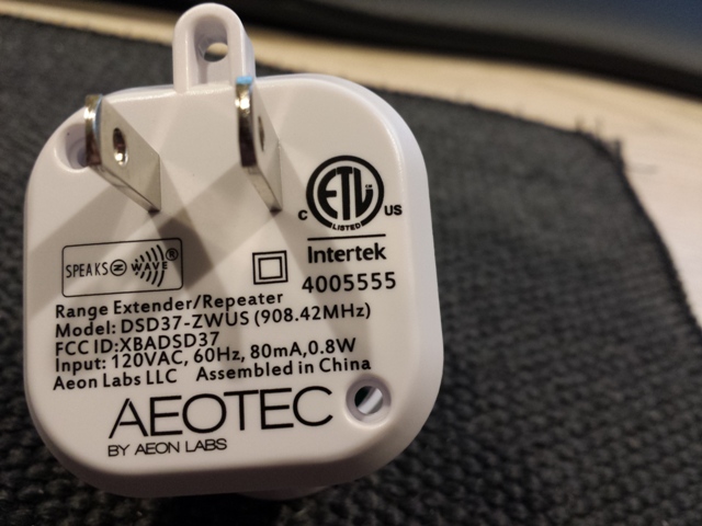
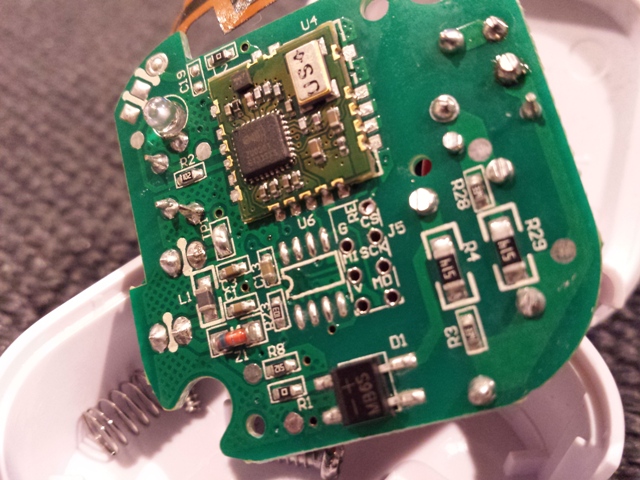
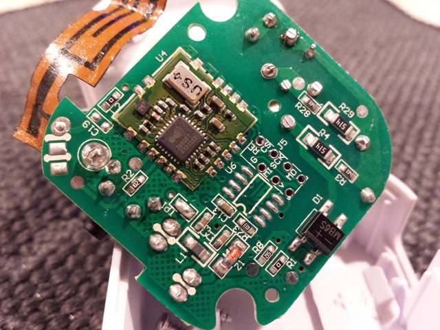
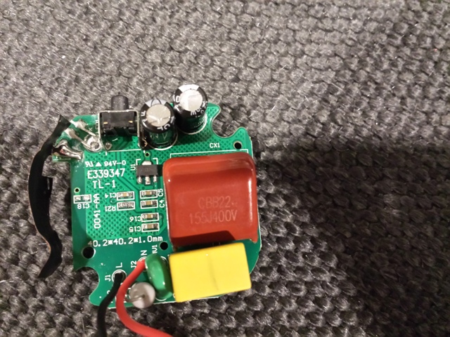
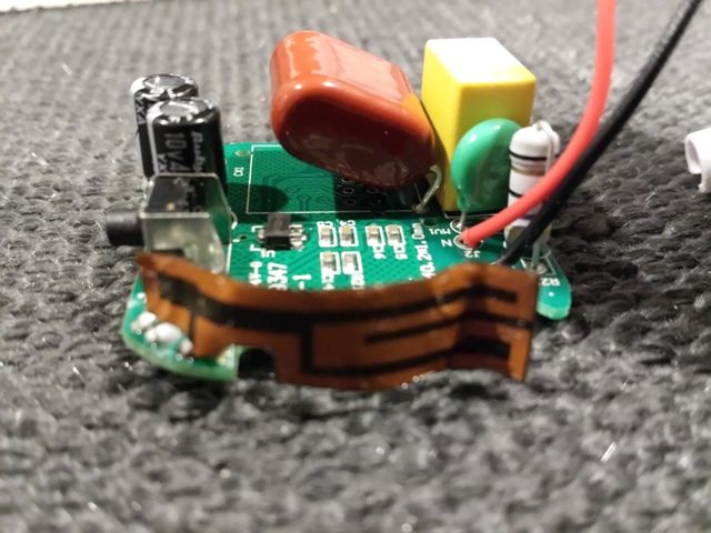
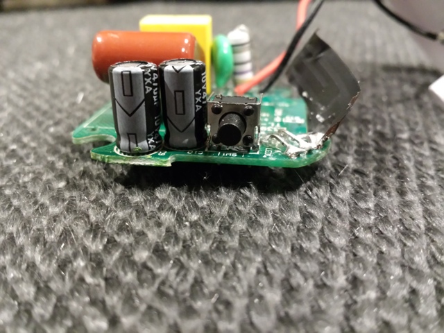
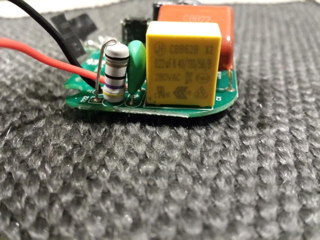
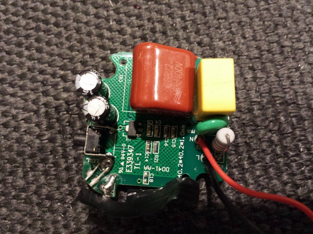
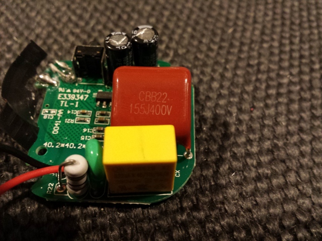
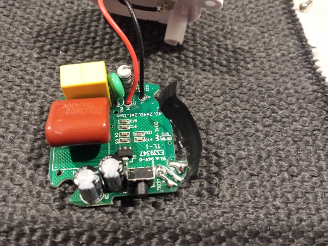
With the # of components and the # of boards we need it is really doable...Don't know if this will help you with some idea's but I pulled apart my Aeotec Zwave extender and took some pics. If you need me to get any other info from any of the components just let me know.
This thing is pretty small. and is powered from Mains
-
Don't know if this will help you with some idea's but I pulled apart my Aeotec Zwave extender and took some pics. If you need me to get any other info from any of the components just let me know.
This thing is pretty small. and is powered from Mains
-
Don't know if this will help you with some idea's but I pulled apart my Aeotec Zwave extender and took some pics. If you need me to get any other info from any of the components just let me know.
This thing is pretty small. and is powered from Mains
@ServiceXp Thanks it looks pretty much the same as my AEOTEC range extenders.
The only difference is 220v :) -
Hello @marceltrapman, how will you power the board from the mains?
I'm a noob in this things yet.. and I'm trying to make a relay sensor to control lights, also put behind the electrical outlet (220vac).. I'm having trouble figuring out if I should add some kind of transformer for every sensor or maybe distribute a 5vdc line from the controller itself..
Hi! See this examples how to power it from 220V without tranformer.
http://www.designercircuits.com/DesignNote1a.pdf
Hello! It looks like you're interested in this conversation, but you don't have an account yet.
Getting fed up of having to scroll through the same posts each visit? When you register for an account, you'll always come back to exactly where you were before, and choose to be notified of new replies (either via email, or push notification). You'll also be able to save bookmarks and upvote posts to show your appreciation to other community members.
With your input, this post could be even better 💗
Register Login