Skip to content
  • MySensors
  • OpenHardware.io
  • Categories
  • Recent
  • Tags
  • Popular
Skins
  • Light
  • Brite
  • Cerulean
  • Cosmo
  • Flatly
  • Journal
  • Litera
  • Lumen
  • Lux
  • Materia
  • Minty
  • Morph
  • Pulse
  • Sandstone
  • Simplex
  • Sketchy
  • Spacelab
  • United
  • Yeti
  • Zephyr
  • Dark
  • Cyborg
  • Darkly
  • Quartz
  • Slate
  • Solar
  • Superhero
  • Vapor

  • Default (No Skin)
  • No Skin
Collapse
Brand Logo
  1. Home
  2. My Project
  3. Powering mote 24/7 using only a supercap and solar

Powering mote 24/7 using only a supercap and solar

Scheduled Pinned Locked Moved My Project
239 Posts 10 Posters 122.5k Views 14 Watching
  • Oldest to Newest
  • Newest to Oldest
  • Most Votes
Reply
  • Reply as topic
Log in to reply
This topic has been deleted. Only users with topic management privileges can see it.
  • N Offline
    N Offline
    NeverDie
    Hero Member
    wrote on last edited by NeverDie
    #23

    After playing around with the Tindie board, I think it's safe to say that for a low light energy harvesting application, having the LED on the board is a bug, not a feature because it rapidly throws away the harvested energy.

    So, I'm making my own BQ25504 board. I'm pretty much done with Version 1, except that the land pattern (see attached) may be a little tricky to do in Diptrace because the pads are not purely rectangle nor purely circular.
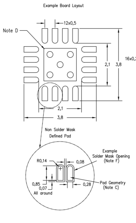
    0_1479826876695_land_pattern.png

    1 Reply Last reply
    0
    • S Offline
      S Offline
      scalz
      Hardware Contributor
      wrote on last edited by scalz
      #24

      i think simple pads should work. But sure it's better to follow recommanded footprint, that can avoid some short during soldering, and is also especially important when using stencils. This kind of shape can help for escaping solder during the process.

      That said, I'm using Eagle...and already did mine :)
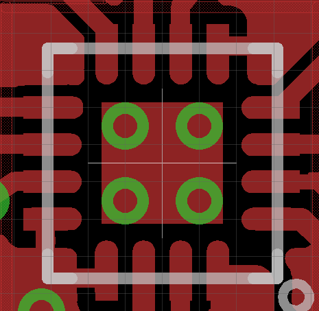
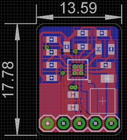
      0_1479833474563_bq25504 footprint.png
      0_1479842780247_bq25504_eval.png
      without led of course!

      I think in parameters you will also need to know how long take your capa to charge (if you want to press twice), what capa voltage range needed regarding bq25504 setup res etc.. I still think indoor it would need a little additional bat, because if it's a mote, lot of chance you could press once, and then wait for x sec/min before pushing again. especially if signing enabled. but perhaps you don't need signing with your mote..

      I hope this helps :)

      Edit: i updated the pic with the bottom. but if you want i can share gerbers if you want, as you're using diptrace

      N 1 Reply Last reply
      0
      • S scalz

        i think simple pads should work. But sure it's better to follow recommanded footprint, that can avoid some short during soldering, and is also especially important when using stencils. This kind of shape can help for escaping solder during the process.

        That said, I'm using Eagle...and already did mine :)
        0_1479833474563_bq25504 footprint.png
        0_1479842780247_bq25504_eval.png
        without led of course!

        I think in parameters you will also need to know how long take your capa to charge (if you want to press twice), what capa voltage range needed regarding bq25504 setup res etc.. I still think indoor it would need a little additional bat, because if it's a mote, lot of chance you could press once, and then wait for x sec/min before pushing again. especially if signing enabled. but perhaps you don't need signing with your mote..

        I hope this helps :)

        Edit: i updated the pic with the bottom. but if you want i can share gerbers if you want, as you're using diptrace

        N Offline
        N Offline
        NeverDie
        Hero Member
        wrote on last edited by
        #25

        @scalz
        Are you connecting your BQ25504 thermal pad to anything on the other side of the board using the via holes? I tentatively connected mine to the large copper ground pour on the other side of the board, on the theory that doing so would help dissipate heat.

        1 Reply Last reply
        0
        • S Offline
          S Offline
          scalz
          Hardware Contributor
          wrote on last edited by
          #26

          @NeverDie nope. just copper on bottom. ground return through your powerpad, in this case, can give less perf.

          N 2 Replies Last reply
          0
          • S scalz

            @NeverDie nope. just copper on bottom. ground return through your powerpad, in this case, can give less perf.

            N Offline
            N Offline
            NeverDie
            Hero Member
            wrote on last edited by NeverDie
            #27

            Yesterday it was sunny outside, and the indoor ambient light was plenty for driving the BQ25504. Today, in stark contrast, it's very overcast outdoors, and the BQ25504 is really struggling. Input voltage from the PV cell with the BQ25504 as the load is hovering around 0.5v or 0.6v. Just a preliminary observation, but I'm not sure the BQ25504 will be useful at input voltages less than about 0.7v. Or maybe the Tiindie board cut some corners or something. I'll have a better idea after I make my own board and compare its performance against the Tindie board.

            1 Reply Last reply
            1
            • S scalz

              @NeverDie nope. just copper on bottom. ground return through your powerpad, in this case, can give less perf.

              N Offline
              N Offline
              NeverDie
              Hero Member
              wrote on last edited by
              #28

              @scalz said:

              @NeverDie nope. just copper on bottom. ground return through your powerpad, in this case, can give less perf.

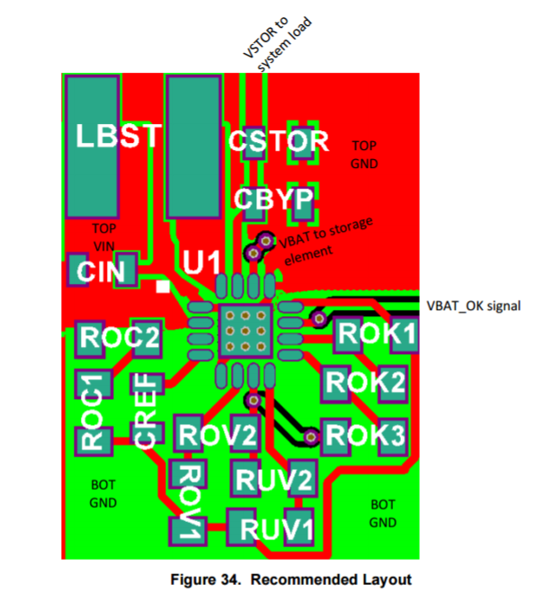
              Are you using tented via's? Because otherwise, it looks as though your thermal pad is electrically connected to the "just copper" on the bottom. But I guess you're not referring to the "just copper" as "ground" because it's not being used as a return path per se? Looking at the "Recommended Layout" (Figure 34 on page 26 of the datasheet), I see it refers to a "Top BND" and a "Bottom GND."

              At the moment I'm not sure what to do, so I changed from having almost the entire bottom connected to ground to just creating an equivalent thermal pad on the bottom that's the same size as on the top, which is electrically connected via the 5 via's. I haven't specified that the via's be electrically isolated from the top thermal pad, because in the TI diagram (which I posted above) it doesn't appear that they are.

              1 Reply Last reply
              0
              • N Offline
                N Offline
                NeverDie
                Hero Member
                wrote on last edited by NeverDie
                #29

                Problem solved. Looking more closely at the datasheet's "recommended layout," regular oval pads should be fine:
                0_1479917570580_oval.png
                So, no need to go exotic on the pad geometry. I can't tell from looking at it whether the thermal pad on the bottom is isolated from "bottom GND" or not, though.

                N 1 Reply Last reply
                0
                • N NeverDie

                  Problem solved. Looking more closely at the datasheet's "recommended layout," regular oval pads should be fine:
                  0_1479917570580_oval.png
                  So, no need to go exotic on the pad geometry. I can't tell from looking at it whether the thermal pad on the bottom is isolated from "bottom GND" or not, though.

                  N Offline
                  N Offline
                  NeverDie
                  Hero Member
                  wrote on last edited by NeverDie
                  #30
                  This post is deleted!
                  N 1 Reply Last reply
                  0
                  • N NeverDie

                    This post is deleted!

                    N Offline
                    N Offline
                    NeverDie
                    Hero Member
                    wrote on last edited by NeverDie
                    #31
                    This post is deleted!
                    1 Reply Last reply
                    0
                    • N Offline
                      N Offline
                      NeverDie
                      Hero Member
                      wrote on last edited by
                      #32
                      This post is deleted!
                      1 Reply Last reply
                      0
                      • N Offline
                        N Offline
                        NeverDie
                        Hero Member
                        wrote on last edited by NeverDie
                        #33

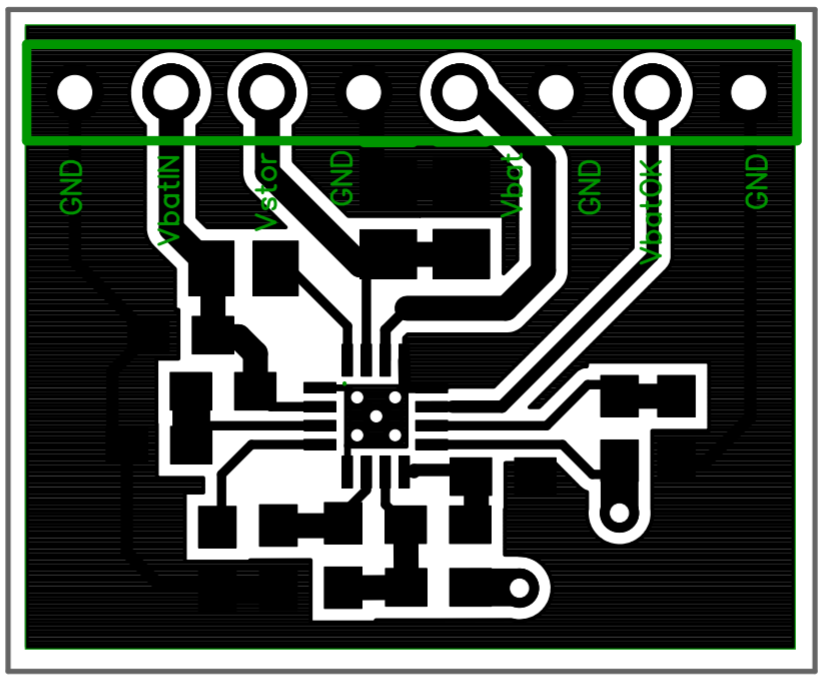
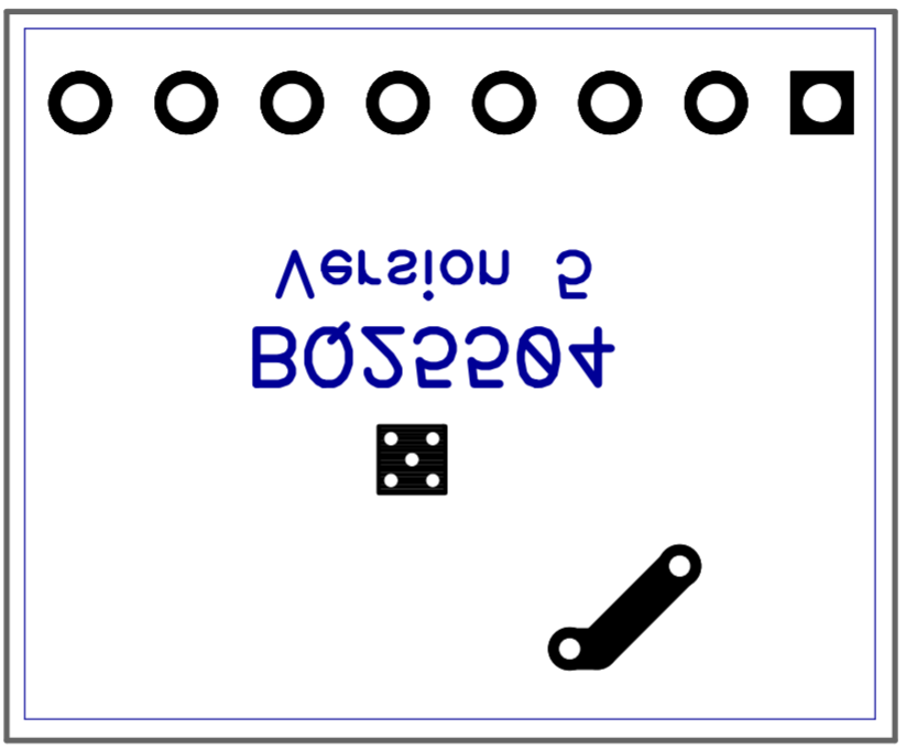
                        Here's what I'm going with for now:
                        0_1479924552790_BQ25504_v5_top.png
                        0_1479924566770_BQ25504_v5_bottom.png

                        As you can see, this one uses only one ground plane. Board size is 22mmx18mm. It uses 0603 and 0805 discrete parts, which for me makes it easier to hand solder. The only tricky part to hand solder will be the BQ25504 itself, but there's nothing I can do about that.

                        1 Reply Last reply
                        0
                        • S Offline
                          S Offline
                          scalz
                          Hardware Contributor
                          wrote on last edited by
                          #34

                          @NeverDie
                          sorry for delay..
                          i have a pad on bottom but it's not grounded on the bottom side. the power pad is grounded only on top. i don't remember but you should have a layout guideline included with the circuit footprint, for explaining.
                          i also use 0603/0805.

                          N 1 Reply Last reply
                          0
                          • N Offline
                            N Offline
                            NeverDie
                            Hero Member
                            wrote on last edited by NeverDie
                            #35

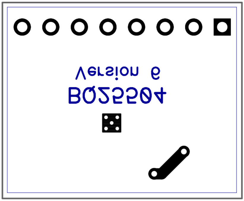
                            I guess my oval pads reverted to the default pattern when I re-synced with the schematic. So, fixing that again, here's what I'm going with:
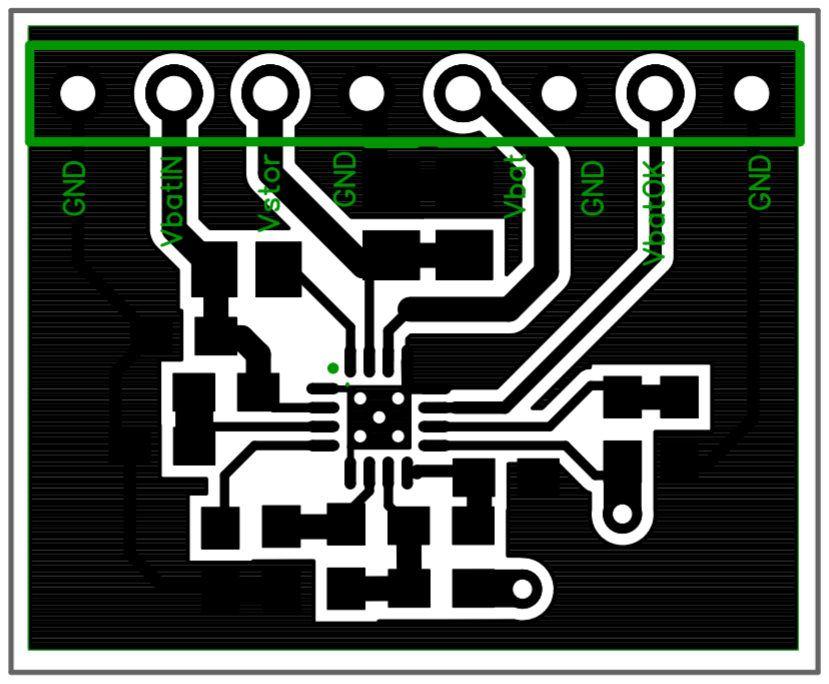
                            0_1479927030669_BQ25504_v6_top.png
                            0_1479927049360_BQ25504_v6_bottom.png
                            There's a bit more clean-up I should probably do, but I need to learn a bit more about Diptrace before I can do it. Meanwhile, I sent Version 6 to the fab, since fabbing is the critical path.

                            1 Reply Last reply
                            0
                            • S scalz

                              @NeverDie
                              sorry for delay..
                              i have a pad on bottom but it's not grounded on the bottom side. the power pad is grounded only on top. i don't remember but you should have a layout guideline included with the circuit footprint, for explaining.
                              i also use 0603/0805.

                              N Offline
                              N Offline
                              NeverDie
                              Hero Member
                              wrote on last edited by
                              #36

                              @scalz said:

                              i also use 0603/0805.

                              In that case, if you want to post your fab files, I can post mine. Then we can have a healthy competition to see whether they work the same or whether one works better than the other.

                              1 Reply Last reply
                              0
                              • S Offline
                                S Offline
                                scalz
                                Hardware Contributor
                                wrote on last edited by scalz
                                #37

                                @NeverDie
                                oh, no competition... or let me win please :laughing: I'm joking. that said i'm not sure, but I think i see Wally on your board ;)
                                I'm back in an hour for sharing. i need to assemble few boards for myself :)

                                N 1 Reply Last reply
                                0
                                • S scalz

                                  @NeverDie
                                  oh, no competition... or let me win please :laughing: I'm joking. that said i'm not sure, but I think i see Wally on your board ;)
                                  I'm back in an hour for sharing. i need to assemble few boards for myself :)

                                  N Offline
                                  N Offline
                                  NeverDie
                                  Hero Member
                                  wrote on last edited by NeverDie
                                  #38

                                  @scalz said:

                                  i'm not sure, but I think i see Wally on your board ;)

                                  LOL. You probably need better ventilation when you're soldering. The fumes are getting to you. :laughing:

                                  N S 2 Replies Last reply
                                  0
                                  • N NeverDie

                                    @scalz said:

                                    i'm not sure, but I think i see Wally on your board ;)

                                    LOL. You probably need better ventilation when you're soldering. The fumes are getting to you. :laughing:

                                    N Offline
                                    N Offline
                                    NeverDie
                                    Hero Member
                                    wrote on last edited by NeverDie
                                    #39

                                    Interestingly, in today's mail I received the "BQ25504 Stripped" PCB
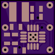
                                    alt text
                                    https://oshpark.com/shared_projects/CYdxpE9S

                                    that I ordered on November 16. That's about twice faster than their normal turnaround speed when I send them new fab files. The board itself is noticeably smaller than the Tindie board.

                                    1 Reply Last reply
                                    0
                                    • N NeverDie

                                      @scalz said:

                                      i'm not sure, but I think i see Wally on your board ;)

                                      LOL. You probably need better ventilation when you're soldering. The fumes are getting to you. :laughing:

                                      S Offline
                                      S Offline
                                      scalz
                                      Hardware Contributor
                                      wrote on last edited by scalz
                                      #40

                                      @NeverDie said:

                                      @scalz said:

                                      i'm not sure, but I think i see Wally on your board ;)

                                      LOL. You probably need better ventilation when you're soldering. The fumes are getting to you. :laughing:

                                      :laughing: no fumes tonight, reflow oven working for me :)

                                      Wally is in your GND pour, in each of your board I think.
                                      I mean you should not have any gnd around some settings resistors and capa.
                                      Check carefully the section 11.1 Layout Guidelines in datasheet.
                                      This is why on the reference layout you see Top GND only on half board. Or then it may happen less performance depending of mutliple factors.
                                      It's also explained how to route the GND.

                                      That said, in case it can help, here is my gerbers https://www.dropbox.com/s/tugdbc3cfrlmdu7/bq25504_gerbers.rar?dl=0

                                      Enjoy

                                      N 1 Reply Last reply
                                      0
                                      • S scalz

                                        @NeverDie said:

                                        @scalz said:

                                        i'm not sure, but I think i see Wally on your board ;)

                                        LOL. You probably need better ventilation when you're soldering. The fumes are getting to you. :laughing:

                                        :laughing: no fumes tonight, reflow oven working for me :)

                                        Wally is in your GND pour, in each of your board I think.
                                        I mean you should not have any gnd around some settings resistors and capa.
                                        Check carefully the section 11.1 Layout Guidelines in datasheet.
                                        This is why on the reference layout you see Top GND only on half board. Or then it may happen less performance depending of mutliple factors.
                                        It's also explained how to route the GND.

                                        That said, in case it can help, here is my gerbers https://www.dropbox.com/s/tugdbc3cfrlmdu7/bq25504_gerbers.rar?dl=0

                                        Enjoy

                                        N Offline
                                        N Offline
                                        NeverDie
                                        Hero Member
                                        wrote on last edited by NeverDie
                                        #41

                                        @scalz

                                        What is "Wally"? I haven't heard that term before, and it's not in the datasheet either. I thought you were jokingly making an obscure reference to Waldo, as in "Where's Waldo?" That's why I had thought the fumes must have gotten to you. I realize now that Wally must instead be a French electrical term of some kind.

                                        1 Reply Last reply
                                        0
                                        • S Offline
                                          S Offline
                                          scalz
                                          Hardware Contributor
                                          wrote on last edited by
                                          #42

                                          @NeverDie
                                          lol
                                          yep you were right, where's waldo/wally but where i live we say Charlie :)

                                          N 1 Reply Last reply
                                          0

                                          Hello! It looks like you're interested in this conversation, but you don't have an account yet.

                                          Getting fed up of having to scroll through the same posts each visit? When you register for an account, you'll always come back to exactly where you were before, and choose to be notified of new replies (either via email, or push notification). You'll also be able to save bookmarks and upvote posts to show your appreciation to other community members.

                                          With your input, this post could be even better 💗

                                          Register Login
                                          Reply
                                          • Reply as topic
                                          Log in to reply
                                          • Oldest to Newest
                                          • Newest to Oldest
                                          • Most Votes


                                          9

                                          Online

                                          12.0k

                                          Users

                                          11.2k

                                          Topics

                                          113.4k

                                          Posts


                                          Copyright 2025 TBD   |   Forum Guidelines   |   Privacy Policy   |   Terms of Service
                                          • Login

                                          • Don't have an account? Register

                                          • Login or register to search.
                                          • First post
                                            Last post
                                          0
                                          • MySensors
                                          • OpenHardware.io
                                          • Categories
                                          • Recent
                                          • Tags
                                          • Popular