[SOLVED] ADAFRUIT rfm69hcw breakout - doesnt respond
-
@tboha
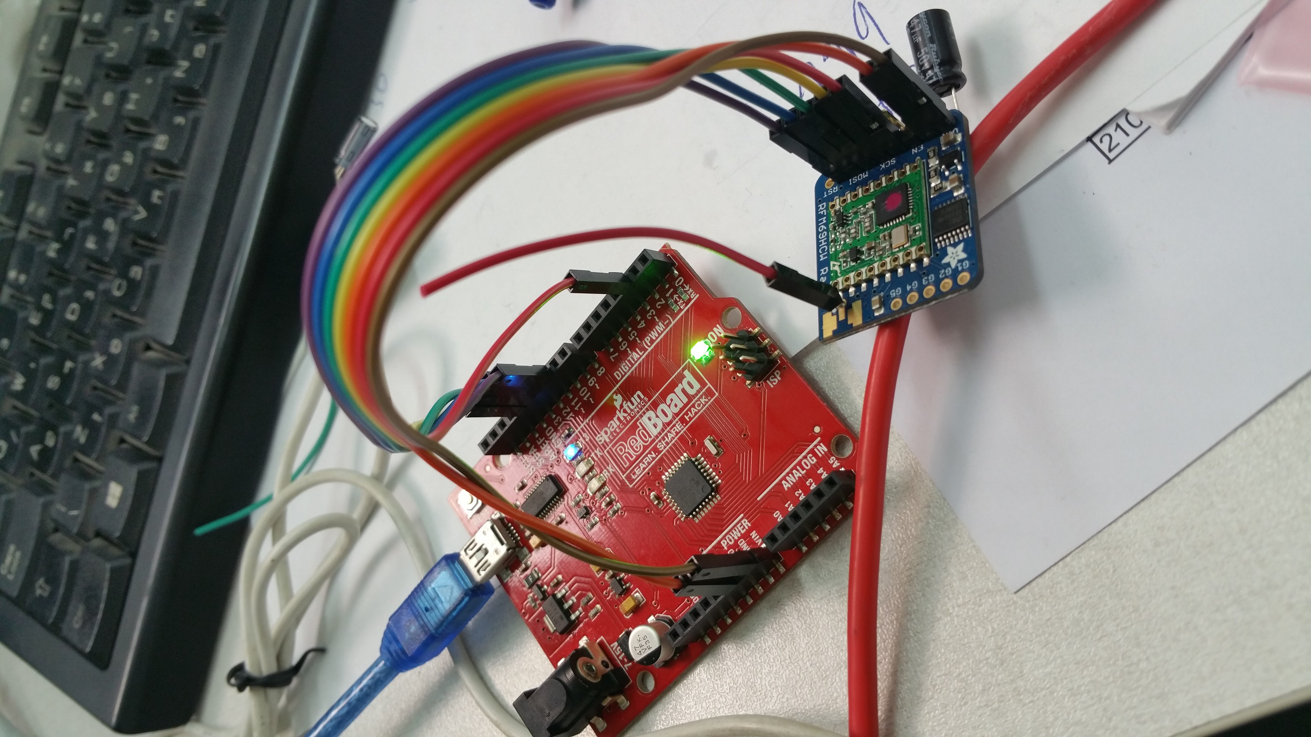
Well, no, the Vin on the adafruit (brown wire) is connected to the vin pin on the uno. I've tried also connecting it to the 5v pin with no success. Also tried switching gnd sockets on the uno.
Im close to sign this issue with recall to adafruit - i ordered 4 boards and they're all with the same behavior. Or maybe i shorted out the ground when i soldered the antenna?@abrasha
Well, I was short of sight (and offset the holes by one...). Sorry.According to https://www.arduino.cc/en/Main/arduinoBoardUno
The power pins are as follows:
- Vin. The input voltage to the Arduino/Genuino board when it's using an external power source (as opposed to 5 volts from the USB connection or other regulated power source). You can supply voltage through this pin, or, if supplying voltage via the power jack, access it through this pin.
- 5V.This pin outputs a regulated 5V from the regulator on the board. The board can be supplied with power either from the DC power jack (7 - 12V), the USB connector (5V), or the VIN pin of the board (7-12V). Supplying voltage via the 5V or 3.3V pins bypasses the regulator, and can damage your board. We don't advise it.
Vin is used to access power from powerjack - before 5V regulators so it may be up to 12V (minus Diode). Supplying your Arduino from USB this pin should be without any voltage (in theory). So Vin (on Arduino) may not be a good choice to supply power to your extension boards.
Before sending back the modules - you got a multimeter and a steady hand?
Just checking power supply on Arduino Vin, breakout board and RFM module? -
@abrasha
Well, I was short of sight (and offset the holes by one...). Sorry.According to https://www.arduino.cc/en/Main/arduinoBoardUno
The power pins are as follows:
- Vin. The input voltage to the Arduino/Genuino board when it's using an external power source (as opposed to 5 volts from the USB connection or other regulated power source). You can supply voltage through this pin, or, if supplying voltage via the power jack, access it through this pin.
- 5V.This pin outputs a regulated 5V from the regulator on the board. The board can be supplied with power either from the DC power jack (7 - 12V), the USB connector (5V), or the VIN pin of the board (7-12V). Supplying voltage via the 5V or 3.3V pins bypasses the regulator, and can damage your board. We don't advise it.
Vin is used to access power from powerjack - before 5V regulators so it may be up to 12V (minus Diode). Supplying your Arduino from USB this pin should be without any voltage (in theory). So Vin (on Arduino) may not be a good choice to supply power to your extension boards.
Before sending back the modules - you got a multimeter and a steady hand?
Just checking power supply on Arduino Vin, breakout board and RFM module?@tboha
on uno:
VIN on uno gives 4.55v
5v gives 4.99von adafruit:
vin to gnd gives 4.99v
cs and mosi gets 4.99v
miso and sck gets 0vnow checking on the green rfm69 original board in the middle:
mosi and nss(cs) recieves 3.2v but after some seconds the d13 led lights on and stays on and then mosi gets 2.87v and nss 1.54v
sck shows 0v and afterwards (d13 led lighting) 0.2v
miso shows 0v all the time.did you meant current measuring? because i didnt succed measuring it by touching with multimeter between the vin on adafruit and 5v on uno (i read somewhere that the MM should be inside the circuit )
-
@tboha
on uno:
VIN on uno gives 4.55v
5v gives 4.99von adafruit:
vin to gnd gives 4.99v
cs and mosi gets 4.99v
miso and sck gets 0vnow checking on the green rfm69 original board in the middle:
mosi and nss(cs) recieves 3.2v but after some seconds the d13 led lights on and stays on and then mosi gets 2.87v and nss 1.54v
sck shows 0v and afterwards (d13 led lighting) 0.2v
miso shows 0v all the time.did you meant current measuring? because i didnt succed measuring it by touching with multimeter between the vin on adafruit and 5v on uno (i read somewhere that the MM should be inside the circuit )
@abrasha
Last first: no, I wasn't aiming on current measurement, but it is a really good idea. It would be interesting where does the current come from, and much more interesting where does it go to when you disconnect ground (assuming your circuit is still working without ground connection...)?Yes, your multimeter should go in series with either VCC or GND.
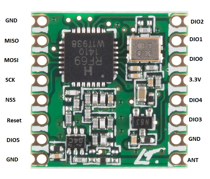
In the photos above the RFM module doesn't match the module on the breakout board. Please have a look at https://www.sparkfun.com/products/13910 here especially photo 4 (and have photo 3 in mind - it has to be flipped over and it is top down).
I tried to label the photo of the RFM69HCW, but I was kind of dazzled by transposition. Please crosscheck this.
 .
.But either way - your measurements give already some hints. Assuming you are powering your Arduino from USB - where do 4.55v come from? Backward current through your power regulator? Although 4.55v would be OK for the adafruit board (because power regulator needs only 3.5 V to start operation).
Did you measure Vin (from Arduino) under load? Is it capable of driving this load (i.e. does voltage drop down significantly under load)?
Next hint: why ever - 3.2V are generated on your board. So your power regulator (probably AP2112-3.3) is oK. But measuring at RFM- 3.3V connector (under load) won't hurt.
If labeling is correct, NSS = 1.54v doesn't make much sense - it would indicate a high frequent switching action (to be expected on SCK or MISO/MOSI during data transfer). NSS (CS) shouldn't probably switch at this high rate.
miso shows 0v all the time.
There should be at least a little data on miso , so it should not be 0 all the time.
And just for completeness - please measure voltage at "EN" at your adafruit board. Voltage should be constant 4.XX Volts (should be Vin), if not - module is disabled.
-
@tboha
on uno:
VIN on uno gives 4.55v
5v gives 4.99von adafruit:
vin to gnd gives 4.99v
cs and mosi gets 4.99v
miso and sck gets 0vnow checking on the green rfm69 original board in the middle:
mosi and nss(cs) recieves 3.2v but after some seconds the d13 led lights on and stays on and then mosi gets 2.87v and nss 1.54v
sck shows 0v and afterwards (d13 led lighting) 0.2v
miso shows 0v all the time.did you meant current measuring? because i didnt succed measuring it by touching with multimeter between the vin on adafruit and 5v on uno (i read somewhere that the MM should be inside the circuit )
@abrasha
PS: Just found schematics of adafruit breakout board. There is already a capacitor (10µF) across Vin - maybe your additional capacitor has some unwanted side effects?
MySensors building instructions advise a capacitor for 3.3V with range problems - not for 5V.Adafruits wiring instructions (very nice and instructive picture) don't mention a capacitor either.
Maybe stripping this capacitor will reduce trouble?
-
@abrasha
PS: Just found schematics of adafruit breakout board. There is already a capacitor (10µF) across Vin - maybe your additional capacitor has some unwanted side effects?
MySensors building instructions advise a capacitor for 3.3V with range problems - not for 5V.Adafruits wiring instructions (very nice and instructive picture) don't mention a capacitor either.
Maybe stripping this capacitor will reduce trouble?
@tboha
The picture you referred to shows the rfm69HW from my sensors page and the adafruit is rfm69Hcw that's why they're don't identical.And I've tried also without capacitor.
Tomorrow I'll check the EN. Maybe I'll wire it and write it high or whatever needed.
Thanks a lot -
@tboha
The picture you referred to shows the rfm69HW from my sensors page and the adafruit is rfm69Hcw that's why they're don't identical.And I've tried also without capacitor.
Tomorrow I'll check the EN. Maybe I'll wire it and write it high or whatever needed.
Thanks a lot@tboha
stripped the CAP
tried this with EN pin: (connected to D7)void setup() { pinMode(7, OUTPUT); digitalWrite(7, LOW); delay(500); digitalWrite(7, HIGH); // Setup locally attached sensors }nothing..
and ther is a steady 4.4v on EN (checking from EN to GNDwhat does the steady 13 led light means?
-
@tboha
stripped the CAP
tried this with EN pin: (connected to D7)void setup() { pinMode(7, OUTPUT); digitalWrite(7, LOW); delay(500); digitalWrite(7, HIGH); // Setup locally attached sensors }nothing..
and ther is a steady 4.4v on EN (checking from EN to GNDwhat does the steady 13 led light means?
@abrasha
I tested Vin behavior under load on my "original" UNO which displays 4.5V at Vin when powered through USB.
No Load = 4.5V, load 10mA results in 4.2V, load 150mA (which is required by RFM69HCW-breakout board so far I remember) results in 3.8V. Maybe transient load response is much worse than this, but my Multimeter does only 2 measurements per second.
I think it is safe to stay away from Vin on your Arduino (which you apparently are doing already).According to schematics, "EN" is tied to Vin via 100k. Supplying Vin with 4.99V and measuring 4.4V on Pin "EN" could indicate your multimeter having a relatively low input impedance (about 1M ?). But either way - EN shuts off only below 0.4V, and 4V seem to be a reasonable margin (transients excluded). So this is not the reason for strange behavior.
D13 may be a good point. D13 is tied to Pin 13 (SCK) and via 1k and a (blue?) LED to GND. In my setup (NRF24L01+) there is only a dim flashing when data transmissions occur. So "bright" light on D13 could indicate a permanent data transmission (which your measurements on MISO/MOSI don't support) or there is a noticeable DC component -- which shouldn't be there. Measuring DC on Pin 13 may give a hint.
It is not likely that Pin 13 is our "lost" GND - in theory impedance (especially with a blue LED) is way to high.To save some time - you got a spare Arduino? Consider building a second sensor (you wrote you got some more Adafruit breakout boards). Take the Adafruit wiring instructions mentioned above and do a close copy of that setup.
Another option would be to exchange the RFM69 module from your GW with the Adafruit breakout boards. If this would be functional - the board(s) are ok.
If you could afford, keep your current setup for further examinations. Although your basic question is quite interesting and unique (my setup works - but it shouldn't) don't get distracted from your way which is probably doing some measurements of your home environment and not of some hardware ( though it is still interesting anyway).
-
@abrasha
I tested Vin behavior under load on my "original" UNO which displays 4.5V at Vin when powered through USB.
No Load = 4.5V, load 10mA results in 4.2V, load 150mA (which is required by RFM69HCW-breakout board so far I remember) results in 3.8V. Maybe transient load response is much worse than this, but my Multimeter does only 2 measurements per second.
I think it is safe to stay away from Vin on your Arduino (which you apparently are doing already).According to schematics, "EN" is tied to Vin via 100k. Supplying Vin with 4.99V and measuring 4.4V on Pin "EN" could indicate your multimeter having a relatively low input impedance (about 1M ?). But either way - EN shuts off only below 0.4V, and 4V seem to be a reasonable margin (transients excluded). So this is not the reason for strange behavior.
D13 may be a good point. D13 is tied to Pin 13 (SCK) and via 1k and a (blue?) LED to GND. In my setup (NRF24L01+) there is only a dim flashing when data transmissions occur. So "bright" light on D13 could indicate a permanent data transmission (which your measurements on MISO/MOSI don't support) or there is a noticeable DC component -- which shouldn't be there. Measuring DC on Pin 13 may give a hint.
It is not likely that Pin 13 is our "lost" GND - in theory impedance (especially with a blue LED) is way to high.To save some time - you got a spare Arduino? Consider building a second sensor (you wrote you got some more Adafruit breakout boards). Take the Adafruit wiring instructions mentioned above and do a close copy of that setup.
Another option would be to exchange the RFM69 module from your GW with the Adafruit breakout boards. If this would be functional - the board(s) are ok.
If you could afford, keep your current setup for further examinations. Although your basic question is quite interesting and unique (my setup works - but it shouldn't) don't get distracted from your way which is probably doing some measurements of your home environment and not of some hardware ( though it is still interesting anyway).
@tboha
checked now.
D13 shows 0v (measuring on the uno itself) and after some seconds, when it lits up forever it shows 0.3v and the serial output prints these two new lines:0;255;3;0;9;TSM:FAIL:RE-INIT
0;255;3;0;9;TSM:INITalso , about the VIN discussion, why does mysensors advice to connect 5v to 3,3v regulator to VIN? on the connect the radio page
about more boards - i only have these 5 adafruit breakouts. all other nodes and GW are working on nrf24. so nothing to compare. and all 5 do the same error
-
@abrasha
I tested Vin behavior under load on my "original" UNO which displays 4.5V at Vin when powered through USB.
No Load = 4.5V, load 10mA results in 4.2V, load 150mA (which is required by RFM69HCW-breakout board so far I remember) results in 3.8V. Maybe transient load response is much worse than this, but my Multimeter does only 2 measurements per second.
I think it is safe to stay away from Vin on your Arduino (which you apparently are doing already).According to schematics, "EN" is tied to Vin via 100k. Supplying Vin with 4.99V and measuring 4.4V on Pin "EN" could indicate your multimeter having a relatively low input impedance (about 1M ?). But either way - EN shuts off only below 0.4V, and 4V seem to be a reasonable margin (transients excluded). So this is not the reason for strange behavior.
D13 may be a good point. D13 is tied to Pin 13 (SCK) and via 1k and a (blue?) LED to GND. In my setup (NRF24L01+) there is only a dim flashing when data transmissions occur. So "bright" light on D13 could indicate a permanent data transmission (which your measurements on MISO/MOSI don't support) or there is a noticeable DC component -- which shouldn't be there. Measuring DC on Pin 13 may give a hint.
It is not likely that Pin 13 is our "lost" GND - in theory impedance (especially with a blue LED) is way to high.To save some time - you got a spare Arduino? Consider building a second sensor (you wrote you got some more Adafruit breakout boards). Take the Adafruit wiring instructions mentioned above and do a close copy of that setup.
Another option would be to exchange the RFM69 module from your GW with the Adafruit breakout boards. If this would be functional - the board(s) are ok.
If you could afford, keep your current setup for further examinations. Although your basic question is quite interesting and unique (my setup works - but it shouldn't) don't get distracted from your way which is probably doing some measurements of your home environment and not of some hardware ( though it is still interesting anyway).
-
@tboha
checked now.
D13 shows 0v (measuring on the uno itself) and after some seconds, when it lits up forever it shows 0.3v and the serial output prints these two new lines:0;255;3;0;9;TSM:FAIL:RE-INIT
0;255;3;0;9;TSM:INITalso , about the VIN discussion, why does mysensors advice to connect 5v to 3,3v regulator to VIN? on the connect the radio page
about more boards - i only have these 5 adafruit breakouts. all other nodes and GW are working on nrf24. so nothing to compare. and all 5 do the same error
@abrasha
Sorry about the delay - I ran out of ideas, and your new measurements are confusing to me.
About Vin:
Could it be possible we talk at cross-purposes?
From the MySensors wiring advice I conclude to connect Arduino-5V to Adafruit-Vin (just the way NRF24L01 with power adapter board).From your picture (which I misinterpreted firstly due to bad sight) you said
Well, no, the Vin on the adafruit (brown wire) is connected to the vin pin on the uno. I've tried also connecting it to the 5v pin with no success. Also tried switching gnd sockets on the uno.
Im close to sign this issue with recall to adafruit - i ordered 4 boards and they're all with the same behavior. Or maybe i shorted out the ground when i soldered the antenna?Connecting Arduino-Vin to Adafruit-Vin would not exactly be according to the rules - but it might work - more likely it would result in unforced errors due to insufficient stabilisation of 5V.
From your measurement 4.99V on Adafruit-Vin I conclude you switched to a 5V Arduino socket - have you?D13 at 0.2V (or 0.3V) shouldn't light up the LED at all unless its really continuous SCK with predominantly low phases.
To solve this you would need an oscilloscope - and this would be inappropriate in my opinion.
No, I don't think it is a library malfunction. I experienced MySensors library as stable and library malfunctions are mostly detected by community at once. For special cases there maybe a lack of functionality but I don't think your setup is very special (besides the breakout-board). And 5 defective boards in a row - not very likely (and Adafruit has a good reputation for engeneering as well as for production).
I am not familiar with RFM69 (altough I was thinking of adding some RFM69 to my setup, but level converters scared me, so I was interested in your type of setup). So far I read about RFM69 you did the approriate #defines. Maybe someone who is working often with RFM69 could check the above sketch?
None of the above explains why your sketch works without GND connection. It's still a miracle.
And as I said before - I ran out of practicable ideas. Next I would try to get a functional two Arduino system according to Adafruit instructions (as well hardware as software). Ok - it's a little like giving up (only a little) - but maybe a practical approach.
-
im starting my movement toward replacing my nrf24 to rfm69-433mhz, and on the same time upgrade to 2.1 library,
i have adafruit rfm69hcw conneced to arduino uno:
by this pinout:
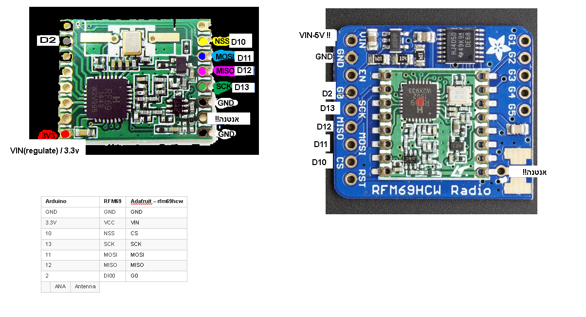
**the word אנטנה!! in the right side of the pcb means antenna...now i uploaded the serial gateway sketch and added all the neccesarry rows:
#define MY_RADIO_RFM69
#define MY_RFM69_FREQUENCY RF69_433MHZ
#define MY_IS_RFM69HW
#define MY_RFM69_NETWORKID 100now all i got is this serial output:
0;255;3;0;9;MCO:BGN:INIT GW,CP=RRNGA--,VER=2.1.0
0;255;3;0;9;TSM:INIT
0;255;3;0;9;TSF:WUR:MS=0
0;255;3;0;9;!TSM:INIT:TSP FAIL
0;255;3;0;9;TSM:FAIL:CNT=1
0;255;3;0;9;TSM:FAIL:PDT
0;255;3;0;9;TSM:FAIL:RE-INIT
0;255;3;0;9;TSM:INIT
both happens with serial gateway sketch and ethernet gateway sketch.
maybe my antenna isnt good? its an ordinary dupont cable with the male connector soldered inside the ANT hole
uno powered by PC usb, and the rfm69 vin connected to VIN (5V also didnt do anything) -
@abrasha I didn't read the whole conversation, but RST is not connected? Leaving RST floating could cause a problem.
-
Tried this on d9 inside the void setup:
pinMode(9, OUTPUT);
  digitalWrite(9, HIGH);
  delay(100);
  digitalWrite(9, LOW);
  delay(100);
The adafruit test sketch put this in order to reset the board in the setup phase.
Didn't workok. case solved. my mistake from the beginning...
i ran the adafruit test sketch without the reset lines, and after the guy in their forum reminded me, i tried this inside void setup, and than i realized that the rfm69 initializes before void setup, so i inserted these lines inside MyTransport.cpp:
void stInitTransition(void)
{
	pinMode(9, OUTPUT); //adafruit rfm69hcw board fix
     digitalWrite(9, HIGH);
     delay(100);
     digitalWrite(9, LOW);
     delay(100);
     TRANSPORT_DEBUG(PSTR("TSM:INIT\n"));
	// initialise status variables
	_transportSM.pingActive = false;
	_transportSM.transportActive = false;
	_transportSM.lastUplinkCheck = 0ul;
and everything is fine.
now i have a running serial-gw and 3 nodes that one of them talks to the gateway directly from a distance which a similar nrf node needed 2 repeaters to do so. exciting! its about 117 meters of direct line, with one plastic transperant door between and only simple standing wire antenna without dipole.thanks everyone,
and a letter to the honorable @Admin (s):
may i propose a sticky thread dedicated to all compatible hardwares which need special configuration in order to work with mysensors. some examples:
this thread :blush:
adafruit feather
w5100 with rfm69i think many members will benefit from such thread for saving time sweat and unnecessary effort for something that should be written somewhere in some dust covered manual
-
ok. case solved. my mistake from the beginning...
i ran the adafruit test sketch without the reset lines, and after the guy in their forum reminded me, i tried this inside void setup, and than i realized that the rfm69 initializes before void setup, so i inserted these lines inside MyTransport.cpp:
void stInitTransition(void)
{
	pinMode(9, OUTPUT); //adafruit rfm69hcw board fix
     digitalWrite(9, HIGH);
     delay(100);
     digitalWrite(9, LOW);
     delay(100);
     TRANSPORT_DEBUG(PSTR("TSM:INIT\n"));
	// initialise status variables
	_transportSM.pingActive = false;
	_transportSM.transportActive = false;
	_transportSM.lastUplinkCheck = 0ul;
and everything is fine.
now i have a running serial-gw and 3 nodes that one of them talks to the gateway directly from a distance which a similar nrf node needed 2 repeaters to do so. exciting! its about 117 meters of direct line, with one plastic transperant door between and only simple standing wire antenna without dipole.thanks everyone,
and a letter to the honorable @Admin (s):
may i propose a sticky thread dedicated to all compatible hardwares which need special configuration in order to work with mysensors. some examples:
this thread :blush:
adafruit feather
w5100 with rfm69i think many members will benefit from such thread for saving time sweat and unnecessary effort for something that should be written somewhere in some dust covered manual
@abrasha ,
I know this is a old post. Glad to see someone else had this problem with these breakout boards. Thanks for the hard work hashing this out. I am new to mysensors. I have been pulling my hair out to get the RFM69HW radios to work with the ESP8266 mqtt gateway. I want to use this with openhab. I was able to back track and get the nRF modules to work, but really would like to get the RFM69HW radios to work. I had several RFM chips and hooked them up to pro min 3.3V 8mhz boards but could only sporadically get one to initialize, but then stop. I broke down and bought the adafruit breakout boards thinking that maybe I could get them to work, but ran into your problem.
I am glad I found your topic on the forum. To clarify, What did you attach to pin 9? Is this the only thing you did fix the problem?
Do the breakout boards have to be used with a 5v arduino?Thanks.
-
Hi, I am also trying to get them to work and stumbled upon this. I will try that and let you know if it works.
@webzter30 I guess he connected it to RST on the Adafruit-board. He mentioned that before. And the breakout does work with 3-5V, so it should work with almost anything. But Adafruit stated that you should use the same power on VIN as on the logic circuits. So for a Nano that would be 5V
EDIT: Works for me! Thanks.
Hello! It looks like you're interested in this conversation, but you don't have an account yet.
Getting fed up of having to scroll through the same posts each visit? When you register for an account, you'll always come back to exactly where you were before, and choose to be notified of new replies (either via email, or push notification). You'll also be able to save bookmarks and upvote posts to show your appreciation to other community members.
With your input, this post could be even better 💗
Register Login