πŸ’¬ Sensebender Gateway


  • Is this device capable of being a gateway for both nRF24L01+ radio and the Hope RF RFM69HCW radio simultaneously ?
    I have some nRF24 nodes and see a lot of new goodies equiped with the RFM69 radio. One gateway to serve both would be excellent !


  • Admin

    No, only one radio type or rs485 is possible at the moment.


  • Admin

    @Sander-Teunissen

    The hardware supports both NRF and RFM69 at the same time, they share the same SPI bus, but has separate chip select lines etc.

    Unfortunately the MySensors library doesn't support multiple transports, so this time it's the software that limits things.


  • Yes ! Itead send me the gateway today


  • @Fabien said in πŸ’¬ Sensebender Gateway:

    Yes ! Itead send me the gateway today

    I have got mine today. Very quick


  • Hardware Contributor

    @tbowmo
    The fact, that MySensors doesn't support more then one radio, was the reason for me not to order the sensebender gateway.

    I am working on a gateway⁄controller based on an arduino due, which supports at least up to 3 serial gateways via hardware serial. It handles ID and time (synced with ntp) requests and does pub/sub to mqtt with readable topics.(inspired by the old mqtt client gateway)


  • @FotoFieber this is a software limitation. Hardware wise I do not see why Sensebender GW cannot handle two (nrf24l01+ and rfm69/rfm95) GWs at the same time


  • Hardware Contributor

    @alexsh1
    The question is: will the software restriction be solved? If not, I do not care if it is a software or a hardware restriction. πŸ™‚


  • Admin

    @FotoFieber

    Well, you need to hack the core anyways, if you want to accomplish your goal.

    You could also help out with the core development, so we can get support for multiple transport on one gateway πŸ˜‰


  • Hardware Contributor

    @tbowmo
    No, I don't have to hack the core. I use the serial API. From an architectural point of view, I don't see the need to change anything in MySensors. A serial controller can be built for under 20€ Including the radio. Why should I add complexity to support more than one radio support with one cpu in MySensors, if I can have the functipnality with the abstraction layer of the serial API? Please keep MySensors s simple as possible.


  • Contest Winner

    @FotoFieber simple for who? Simplicity also involve maintenance and code complexity. What about testability and regression testing? Nobody gets paid for maintaining mysensors.


  • Admin

    @FotoFieber

    But you ditched the sensebender Gateway, as it doesn't support multiple radios at the same time? Now you are saying that you would keep it as one radio per gateway?

    This doesn't make sense πŸ™‚


  • Hardware Contributor

    @tbowmo
    Maybe the design of the sensebender gateway doesn't make sense to my architectural viewpoint....


  • @FotoFieber This is a question for the MySensors dev team. Sensebender can handle both radios. Currently, there is a software restriction.


  • @FotoFieber No, you do have to hack the core if you want both radios to be handled properly, i.e. to handle message queues with corresponding radios. For example, sending a message is done via rfm69 only and not via nrf24l01+


  • Contest Winner

    The architecture we use would place this kind of situation to the controller to solve. One gw per network. So one gw for nrf and one for rfm.
    HW is cheap, and library should be kept simple.


  • Hardware Contributor

    @Anticimex
    One gateway per radio, that is what I think is best. πŸ‘

    What I try to do, is to implement a controller with arduino due for up to three serial gateways. If there would be a solution for ethernet&rfm69 I may not have invested time in this. πŸ˜†

    0_1485703507553_DueMysMQTT_Steckplatine.png


  • Admin

    @FotoFieber

    Well sensebender GW supports rfm69 with ethernet πŸ˜‰


  • Hardware Contributor

    @tbowmo
    Yes, that is really nice. πŸ‘

    My other goal was to have a new MQTTClientGateway, as it existed with MySensors 1.1 (which is not only a gateway, but a controller too). It would have been really painful to add it to MySensors 2.1.x, as I would have to patch core files. It is much easier, to throw hardware at it. πŸ˜†


  • @tbowmo More practical question. I have received the GW and it already has MySensors 2.1.0 software. Excellent service by Itead. Can you please help me how to map LEDs in the GW sketch? I can see that they are connected to pins 38, 41, 42, 39, 40 as LED1, LED2, LED3, LED4 and LED5. Thanks


  • Admin

    @alexsh1

    you should be able to use LED_BLUE, LED_GREEN etc. defines (or even just LED_1, LED_2..) in your sketch, to access the different LED's on board the gateway. That is, if you are using the SenseBender GW hardware support files in arduino (installation instructions are here https://github.com/mysensors/ArduinoBoards)

    Also, look at the board definition files, located here https://github.com/mysensors/ArduinoHwSAMD/blob/master/variants/mysensors_gw/variant.cpp
    and here https://github.com/mysensors/ArduinoHwSAMD/blob/master/variants/mysensors_gw/variant.h


  • @tbowmo Excellent links, many thanks. BTW the board is working with the standard arduino samd, the problem I suppose comes with things LEDs.


  • Admin

    @alexsh1

    You might be able to compile with the standard arduino zero BSP files. But the IO mapping is not the same at all.. I have swapped some pins to make routing a bit easier. Also the SPI channels are configured a bit differently than the standard arduino, if I remember right. So I will advise to use the mysensors gateway BSP files..


  • @tbowmo it is already done. Thanks to your link I have now Sensebender Gateway board added.
    Waiting for an ethernet board now, it has stuck in the post


  • @tbowmo : Did you try to use this board with platformio ?


  • Admin

    @Fabien

    No, platformio is still on my bucketlist.. There is just not hours enough for everything πŸ™‚


  • @tbowmo Ok I will install arduino IDE to upgrade it to 2.1.1
    Please post here iwhen you have more information. I think I will try but I have no experience with this architecture.


  • Has anyone designed a case for the sensebender gateway ?


  • Admin

    @delivereath

    I designed one in freecad for the GW and a nrf24l01 with lna/pa and external antenna.

    But I still have some fine tuning to do before releasing it, as the lid locking mechanism didn't turn out like expected.


  • Hardware Contributor

    Tea time..

    Here is my custom box for your RFM69 Sensebender GW ! Beautiful board though πŸ˜‰

    No nail no screw πŸ™‚

    0_1486052016552_Custom box for Sensebender GW.jpg

    0_1486052034817_Plate for Sensebender GW.jpg

    0_1486052057656_Bottom plate for Sensebender GW.jpg

    Last final minor check and i release the files, sure! (i've done one for nrf too in case..)


  • @scalz beautiful box!!!
    Looking forward to print it too as soon as you publish it, but mine will be with nrf24l01+. Having been running both networks, I'm so much in favour of rfm69. It just works. No more caps to stabilise power or any other rf issues.

    I have decided to use Moteino Mega with a built-in antenna as rfm69 gateway though - it is very small and goes inside into an RPi box. And has got more memory than atmega328p


  • @scalz Yeah ! I will print this one.


  • Hardware Contributor

    Little gift.. πŸ™‚

    Custom box for the NRF non PA version:

    0_1486135733912_20170203_161524.jpg

    0_1486135777240_20170203_161550.jpg
    A bit enlarged for NRF.

    0_1486135802750_20170203_162026.jpg

    And here the 3d preview for both versions with my little cheat for bicolor as i've still not added this feature to my printer
    0_1486135971628_assembly_rfm69_nrf_1.png
    You can see i've added a little slot near usb on the NRF version, it's for the leds indication in case box wouldn't be white (no need for white box, you can see it by transparency). I'll do the same for rfm69, and put variant stl with it or not.

    Next Nrf PA version, and that'll be fine πŸ˜‰


  • Admin

    Thank you @scalz!

    0_1486143935594_20170203_182834.jpg


  • @scalz Please share the STL files!


  • Hardware Contributor

    @alexsh1 why, i don't understand 😜

    Here it is : http://www.thingiverse.com/thing:2084269


  • Hardware Contributor

    I'm proud to say enclosure files have been integrated in the MySensors Sensebender GW project and git.
    So you can find the files here at Mysensors.

    Enjoy πŸ™‚


  • Hey it should look like this?

    But you see the gap between the W5100 and Sensebende Gateway.

    0_1486208943376_Sensebender GW 006.JPG

    0_1486208957253_Sensebender GW 007.JPG

    0_1486208970805_Sensebender GW 008.JPG

    0_1486208982183_Sensebender GW 009.JPG

    Sorry for a very poor camera

    //Mattias


  • Admin

    @MLs

    Yes, according to the build instructions here, you can also raise the socket a bit over the pcb.

    The problem is that the ethernet connector is higher than a normal IDC socket, which means you can't insert the board fully in the socket. I have searched for a higher variant of the socket, but haven't found a suitable candidate..


  • @tbowmo What I did was soldering the socket a bit higher. Not a problem with some soldering skills...


  • @scalz Thank you Sir. I am going to probably wait for the PLA version as It has been working a bit better for me.


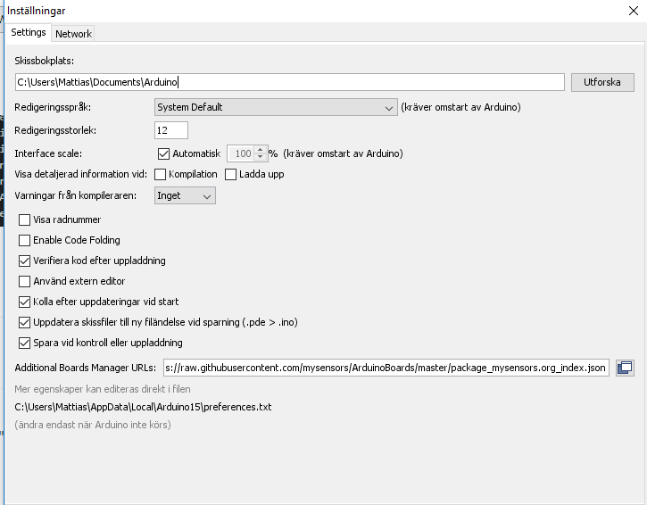
  • Few things about the software side of this. When you plug it into your computer it appears as a "Sensebender GW", with a custom USB VID/PID. You have to override the drivers and use the "Atmel Corp. EDBG CMSIS-DAP" serial port drivers or you will have no serial port at all to communicate with the board.

    Second issue, with the latest Arduino software (1.8.1), and the MySensors SAMD board package installed and MySensor library installed you get an error relating to a missing core "arduino:arduino". Solution to that one is to install the main Arduino SAMD board package which adds the necessary libraries. Secondly, after doing that you will now get another error regarding a missing "Sam.h" file, to fix that you have to manually edit the platform.txt file in "\AppData\Local\Arduino15\packages\MySensors\hardware\samd\1.0.3" with the contents of the one from "\AppData\Local\Arduino15\packages\arduino\hardware\samd\1.6.11" - just being careful to copy over the name and version lines from the top of the Mysensors platform.txt file. After that you are good to go and can finally program the board or get some data out of it πŸ™‚


  • Admin

    We are preparing a new release of the board definitions for our samd. Which fixes the issues with arduino samd 1.6.11.

    It should also contain a driver .inf file for Windows 7/8, for those that needs it (it's not needed on Linux, mac or Windows 10). I had completely forgotten that windows usually needs this inf file to operate correct (I have been using Linux the last 17 years for all my private projects)

    I hope the package will be out tomorrow (sunday) , as I just need to do a couple of tests to verify things.


  • Do you have any example sketch for this gateway? I want to use in my GW radio + wifi module.


  • Admin

    @Viktor-Zeman

    It only support wired ethernet, and USB. For wifi we have ESP8266 gateways instead.

    There are example sketches available in mysensors (see SensebenderGatewaySerial, or just plain GatewayW5100 would work if it's just ethernet module that you want to use)


  • @tbowmo Great, took a an hour or two to work out what was going on. Not used MySensors before so presumed it was something I was doing wrong. I have an RFM69HW soldered on the sensebender GW now with the serial sketch loaded and it appears to be working!


  • Admin

    for info, a new Mysensors SAMD board definition file have been released (1.0.4)

    Includes the following changes:
    Arduino SAMD 1.6.11 supported (the latest arduino board definitions for SAMD)
    Various bits and pieces regarding pin definitions are fixed (a couple of missing defines)
    Windows driver .inf file added.


  • @tbowmo Compiles fine now with 1.0.4, not convinced the drivers are being automatically picked up though. I can force install them by selecting the inf but presumably you want it automatic when someone plugs in the gateway?

    I notice in the arduino SAMD package they have a post-install.bat to seemingly install the inf file - possibly needed?

    It could also be that i've just messed things up with my manual driver install stuff yesterday. I'm on Windows 7 by the way.


  • @tbowmo Also, I notice on Linux (Raspberry Pi 3 running Debian) the device appears as an ACM device rather than the usual TTY device that some might expect. It works fine though so no issues but may confuse alot of people - worth making a note somewhere.


  • @tbowmo

    (for info, a new Mysensors SAMD board definition file have been released (1.0.4))

    Where?


  • @MLs reload board definition from IDE

    I have a little annoying bug : I can't reset de gateway. When resetting, I loose communication with my computer (linux) same after loading a new sketch (last version with IDE 1.8.1 and def 1.0.4))

    [13727.746445] usb 1-1: new full-speed USB device number 9 using xhci_hcd
    [13727.892970] usb 1-1: New USB device found, idVendor=1209, idProduct=6949
    [13727.892974] usb 1-1: New USB device strings: Mfr=1, Product=2, SerialNumber=3
    [13727.892977] usb 1-1: Product: Sensebender GW
    [13727.892980] usb 1-1: Manufacturer: MySensors.org
    [13727.895690] cdc_acm 1-1:1.0: ttyACM1: USB ACM device
    [13749.066589] usb 1-1: USB disconnect, device number 9
    

    So I can't check debug messages from init.


  • Admin

    @MLs

    Check out the setup instructions here

    and perhaps this


  • Admin

    @Fabien

    Are you using it as an ethernet gw, or standard serial gw? If serial GW, then the gateway waits until something connects to the serial device

    The ethernet gw doesn't wait for something to connect. But you can hack the core, change hwInit() function in MyHwSAMD.cpp:

    original

    void hwInit()
    {
            MY_SERIALDEVICE.begin(MY_BAUD_RATE);
    #if defined(MY_GATEWAY_SERIAL)
            while (!MY_SERIALDEVICE) {}
    #endif
            Wire.begin();
    }
    

    modify to this

    void hwInit()
    {
            MY_SERIALDEVICE.begin(MY_BAUD_RATE);
            while (!MY_SERIALDEVICE) {}
            Wire.begin();
    }
    

    It will make the gateway halt the initialization until something connects to the USB device.

    Be advised, that if you don't have it connected to a computer, then it will not start up correctly.. That is why you need to hack the core to enable it..


  • @tbowmo

    When I try to upload sketch

    Arduino:1.8.0 (Windows 10), Kort:"Arduino/Genuino Zero (Native USB Port)"
    
    Sketch uses 46488 bytes (17%) of program storage space. Maximum is 262144 bytes.
    No device found on COM4
    An error occurred while uploading the sketch
    Invalid version found: 1.04
    Invalid version found: 1.04
    
    This report would have more information with
    "Show verbose output during compilation"
    option enabled in File -> Preferences.
    

    When I use the serial monitor

    0;255;3;0;9;MCO:BGN:INIT GW,CP=RNNGS--,VER=2.1.0
    0;255;3;0;9;TSF:LRT:OK
    0;255;3;0;9;TSM:INIT
    0;255;3;0;9;TSF:WUR:MS=0
    0;255;3;0;9;TSM:INIT:TSP OK
    0;255;3;0;9;TSM:INIT:GW MODE
    0;255;3;0;9;TSM:READY:ID=0,PAR=0,DIS=0
    0;255;3;0;9;MCO:REG:NOT NEEDED
    0;255;3;0;14;Gateway startup complete.
    0;255;0;0;18;2.1.0
    0;255;3;0;9;MCO:BGN:STP
    0;255;3;0;9;MCO:BGN:INIT OK,TSP=1
    0;255;3;0;9;TSF:MSG:READ,27-27-0,s=0,c=1,t=1,pt=7,l=5,sg=0:45.6
    27;0;1;0;1;45.6
    0;255;3;0;9;TSF:MSG:READ,23-23-0,s=1,c=1,t=0,pt=7,l=5,sg=0:8.4
    23;1;1;0;0;8.4
    0;255;3;0;9;TSF:MSG:READ,23-23-0,s=1,c=1,t=0,pt=7,l=5,sg=0:8.3
    23;1;1;0;0;8.3
    0;255;3;0;9;TSF:MSG:READ,23-23-0,s=0,c=1,t=1,pt=7,l=5,sg=0:51.8
    23;0;1;0;1;51.8
    0;255;3;0;9;TSF:MSG:READ,22-22-0,s=1,c=1,t=0,pt=7,l=5,sg=0:3.4
    22;1;1;0;0;3.4
    0;255;3;0;9;TSF:MSG:READ,23-23-0,s=0,c=1,t=1,pt=7,l=5,sg=0:52.0
    23;0;1;0;1;52.0
    0;255;3;0;9;TSF:MSG:READ,22-22-0,s=1,c=1,t=0,pt=7,l=5,sg=0:3.5
    22;1;1;0;0;3.5
    0;255;3;0;9;TSF:MSG:READ,23-23-0,s=1,c=1,t=0,pt=7,l=5,sg=0:8.2
    23;1;1;0;0;8.2
    0;255;3;0;9;TSF:MSG:READ,23-23-255,s=255,c=3,t=7,pt=0,l=0,sg=0:
    0;255;3;0;9;TSF:MSG:BC
    0;255;3;0;9;TSF:MSG:FPAR REQ,ID=23
    0;255;3;0;9;TSF:PNG:SEND,TO=0
    0;255;3;0;9;TSF:CKU:OK
    0;255;3;0;9;TSF:MSG:GWL OK
    0;255;3;0;9;!TSF:MSG:SEND,0-0-23-23,s=255,c=3,t=8,pt=1,l=1,sg=0,ft=0,st=NACK:0
    0;255;3;0;9;TSF:MSG:READ,23-23-0,s=0,c=1,t=1,pt=7,l=5,sg=0:52.4
    23;0;1;0;1;52.4
    0;255;3;0;9;TSF:MSG:READ,22-22-0,s=1,c=1,t=0,pt=7,l=5,sg=0:3.4
    22;1;1;0;0;3.4
    0;255;3;0;9;TSF:MSG:READ,23-23-0,s=1,c=1,t=0,pt=7,l=5,sg=0:8.1
    23;1;1;0;0;8.1


    I USE IDE 1.80

    0_1486306348742_InstΓ€llningar.png

    Which card should I choose to get upload sketch on GW

    //Mattias


  • Admin

    @MLs

    have you installed the mysensors board files? And chosen the Sensebender Gateway as target platform?

    (Seems that you are using Arduino/Genuino Zero as target?)


  • @tbowmo I'm using the serial sketch.
    I have few issues (I think) :

    • when I want to upload a new sketch, first time after powering by computer, every led goes off and SBGW seems to be disconnected. When I unplug/plug, no led are on or blink, but detection is ok and I can upload a firmware.
    • When I press RESET after connecting SBGW on my computer, all led goes off and SBGW disconnect.

    And it doesn't seems to wait when I plug computer, led start blinking ...


  • Admin

    @Fabien

    Is it windows or linux? Linux (ubuntu) have a bad habit of letting modem manager snatch any ACM devices that is connected to the computer.


  • @tbowmo

    Yes, I have installed MYSensors boards but find only micro

    0_1486308954042_Boards.png

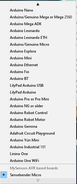
    So therefore, I tried another card.

    //Mattias


  • @MLs

    I found the problem myself. Had just installed Micro


  • @tbowmo said in πŸ’¬ Sensebender Gateway:

    modem manager snatch any ACM devices

    Yes it's ubuntu ... Do you know how to avoid this ? udev ?


  • Ok :

    sudo apt-get --purge remove modemmanager


  • @tbowmo

    Hi i get same error whit Sensebender Ga

    Arduino:1.8.0 (Windows 10), Kort:"Sensebender Gateway"
    
    Build options changed, rebuilding all
    Sketch uses 46720 bytes (17%) of program storage space. Maximum is 262144 bytes.
    No device found on COM4
    An error occurred while uploading the sketch
    Invalid version found: 1.04
    Invalid version found: 1.04
    
    This report would have more information with
    "Show verbose output during compilation"
    option enabled in File -> Preferences.```
    

    No device found on COM4
    But serial monitor works fine with COM4

    //Mattias


  • @MLs In Device Manager what com port is assigned to the sensebender GW? Have you manually installed the inf file?

    com4 is likely the last com port you used in the arduino interface not the one assigned to the GW.


  • @Disca

    No, I have not installed or selected com port.
    Device Manager COM4
    As I understood it so Windows 10 would fix everything, right?

    //Mattias


  • @tbowmo : It's better for seeing debug from start.
    But there is 2 bugs :

    • When you want to upload sketch. /dev/ttyACM0 disapear (and D4 goes off) afterunplu/plug it works for uploading sketch (D4 off) but at the end of uplaod ArduinoIDE makes a soft reset and /dev/ttyACM0 disapear. Works fine after plus/unplug (D4 ON)
    • When pressing reset /dev/ttyACM0 disapear (and D4 goes off). Works fine after plug/unplug


  • @MLs mmm not sure then, it works for me on Windows 7 with 1.8.1 (slightly newer version?)


  • Admin

    @MLs

    I don't have windows installed, so I'm sorry that I can't help with windows specifics.


  • @tbowmo

    Now, I think it feels like hardware failure more than software errors. Will try tomorrow on my second computer with Windows 7 and see if there is any difference.

    //Mattias


  • Admin

    @Fabien

    I added a couple of udev rules, to stop modemmanager take control over the device

    ACTION!="add|change|move", GOTO="local_usb_device_blacklist_end"
    SUBSYSTEM!="usb", GOTO="local_usb_device_blacklist_end"
    ENV{DEVTYPE}!="usb_device",  GOTO="local_usb_device_blacklist_end"
    
    ATTRS{idVendor}=="1209", ENV{ID_MM_DEVICE_IGNORE}="1"
    
    LABEL="local_usb_device_blacklist_end"
    

    Add the above to this file /etc/udev/rules.d/mysensors.rules

    As the USB is native in the arm processor, then it will re-enumerate on the USB port whenever a reset condition occurs. When you press the reset button it will act as a unplug / plug operation (you can see this in dmesg)

    When uploading to the gateway, it will reset itself to enter bootloader.. The bootloader will have another VID/PID combo (VID:1209, PID:6448) than during normal operation (VID:1209, PID:6449).

    I have never seen the problems that you are having, where you need to fysically unplug / plug the device, after you have pressed the reset button (or uploaded a new firmware). And I have uploaded firmware (and pressed the reset button) quite some times πŸ™‚

    Also please note, that if you double tap the reset button, the gateway will enter bootloader mode, and wait for a new sketch to be sent.


  • @tbowmo : Same with udev rules (but this file is not necessary because modemmanger is not installed).
    I try to power SBGW with usb, D4 goes ON. After pressing reset, D4 goes OFF and never goes on (I must unplug/plu usb power). Do you have the same with your board ? Perhaps a problem with bootloader ?


  • Admin

    @Fabien

    D4 is the yellow LED, and the only place it is used is in the onboard selftest routine.

    In my setup, D5 turns on when plugging in the device. If I hit reset one time, it momentarily switches off D5, and then back on. if I hit reset twice, it stays off (bootloader is activated)

    The above is done on my RFM69 debug gateway, so the sketch is for RFM69, but otherwise a standard SensebenderGatewaySerial sketch

    Have you checked dmesg, when plugging in, and when hitting the reset button?

    Have you tried with another USB cable? Have you tried with another computer?


  • I try with 2 different USB cable and 2 computer (1 laptop and 1 desktop). Same problem. With a charger too. And sorry for the mistake, it's D5 (orange)
    On log

    [ 4788.031324] usb 1-8: USB disconnect, device number 6


  • 0_1486421335378_IMG_20170206_234714.jpg
    Thank you @scalz !
    You must have a very well calibrated printer to print it correctly. First try fails (oozing due to overtemp)
    Other side tomorrow !


  • @Disca

    Where did you find the drivers for sensebender GW for Windows 7?

    //Mattias


  • Admin


  • Admin

    @Fabien

    D5 is used by arduino to signal USB serial rx/TX activity.

    Can you post the log lines from dmesg, from when you insert the usb cable, to after you have pressed the reset button?


  • @tbowmo

    I tried to update the drivers in Device Manager / sense bender GW but it failed to install the computer said.

    Therefore, I asked one who wrote that he was using Windows 7

    //Mattias


  • Hardware Contributor

    @MLs
    I'm also still using win7 x64 for my dev and that worked for me.

    Auto install through the Device Manager does not work, nor right-clicking and installing the .inf through Explorer.

    You have to force the install and select the location of the .inf in Device Manager. Then it will ask you if you agree about the driver supplier. Of course you're! And you should be able to see it in Device Manager.


  • There are example program for W5100? The original GatewayW5100 program uses SOFTSPI, different NRF CE/CSN pins? Will work with this hardware properly?


  • @scalz

    Heh've tried both in the device manager and manually. Device Manager, I get an error message.

    0_1486469926862_Enhetshanteraren.png

    And manually, nothing happens.

    0_1486469936775_Manuelt.png

    //Mattias


  • Hardware Contributor

    @MLs
    yep that's what i explained.
    you need to force it in Device Manager. How you're doing in Device manager actually is rather auto, imho πŸ˜‰
    You can try in Device manager to right click on the bad detected device, here Sensebender Gw, and in properties, update driver. At a moment, it should prompt an "Open file" Dialog box (you need to choose the right option in the dialog) and then select your .inf file. And it will ask if you're ok to install a driver from a third party.


  • Admin

    @Dany

    The standard GatewayW5100 example sketch will work on the sensebender gateway. There are conditional compile statements in that sketch, that disables softspi when compiling to the gateway target, and use a hardware SPI instead.

    Remember to choose the correct target in your Arduino IDE


  • Hardware Contributor

    @MLs
    Okay, simpler, forget what i told you, and follow my steps below. I've unstalled mine to show you πŸ˜‰
    Then if it can be useful for others. Nothing fancy here, it can be used for lot of others drivers.

    Step 1: plugin the GW, as you can see it's not detected, and no additional com port.
    0_1486474793485_SBDGW win7 driver install step 1.png

    Step 2: right clic, and update driver
    0_1486474882132_SBDGW win7 driver install step 2.png

    Step 3: click on the 2nd option for searching a driver on your machine
    0_1486474932523_SBDGW win7 driver install step 3.png

    Step 4: Again 2nd option here (you want to search for a driver on your computer)
    0_1486474985503_SBDGW win7 driver install step 4.png

    Step 5: This is a Virtual Serial Com port needed for the GW. So choose COM/LPT for the driver type
    0_1486475057428_SBDGW win7 driver install step 5.png

    Step 6: Now it is asking where the driver (.inf) is stored
    0_1486475102981_SBDGW win7 driver install step 6.png

    Step 7: You can now see that Windows knows what this is about. And tells you this driver is not "signed". No problem we know @tbowmo has done a great job. So, Next!
    0_1486475141843_SBDGW win7 driver install step 7.png

    Step 8: Windows here warns again, saying he doesn't know this driver, so it may not work well. No way, it will work well πŸ˜‰ Click "Yes" to install it.
    0_1486475226673_SBDGW win7 driver install step 8.png

    Step 9: Looks good
    0_1486475299591_SBDGW win7 driver install step 9.png

    Step 10: Tada! Here you can see now the GW is well detected and setup on COM port 24
    0_1486475356373_SBDGW win7 driver install step 10.png

    I can't do better!
    I think you'll get it πŸ™‚


  • @scalz

    Thanks for a super instruction but it is the file itself that the computer says from. It says that the folder contains the no driver

    And the driver in the folder I chose I downloaded here

    https://github.com/mysensors/ArduinoHwSAMD/blob/master/driver/mysensors-samd.inf

    // Mattias


  • @MLs

    When I downloaded the drivers so I make the following step.
    Right-click at the file and save target as.

    //Mattias


  • Admin


  • @hek

    https://github.com/mysensors/ArduinoHwSAMD/tree/master/driver

    I click on the link below the folder drivers

    0_1486482224917_NamnlΓΆs.png

    //Mattias


  • Admin

    No, that will download a github html page.

    Use the link I posted (and save as). It will be the raw content.


  • @hek

    I'll try it tomorrow is not so strange that it did not work for me then.

    //Mattias


  • @hek

    Now, I also got the computer to recognize the card. Thanks for all help.

    The problem was that even when I used save as, the computer renaming the file as a .txt file "mysensors-samd.inf.txt" and not a "mysensors-samd.inf"

    Again, thanks for all the help.

    //Mattias


  • Hi together,

    i have some questions to you! I bought a sensebender gateway and a w5100 Ethernet Modul, but i cant get it to work. When i upload the Gateway5100 Sketch and put my yip address in it, then the GW is booting up i get some Data on the serial port but i cant ping the configured ip address. Then i tried to config via DHCP and see that the GW dont get an IP Address.
    And when i connect the NRF24 Modul then it seems that the GW is not bootin up anymore because i dont get any data on serial port.
    i need your help. Thanks a lot in advance


  • Admin

    @meddie

    Could you please post the logs that you get on the serial port, when the W5100 is attached?

    Do you get anything on the serial port if you configure the sensebender to be a serial gateway, and only add a NRF24 module to it?


  • Hi tbowmo,

    with the gatewayw5100 Sketch i get every 10 seconds 5 lines output on serial monitor:
    The sketch is default i changed only the ip adress

    0;255;3;0;9;TSM:FAIL:RE-INIT
    0;255;3;0;9;TSM:INIT
    0;255;3;0;9;!TSM:INIT:TSP FAIL
    0;255;3;0;9;TSM:FAIL:CNT=3
    0;255;3;0;9;TSM:FAIL:PDT
    0;255;3;0;9;TSM:FAIL:RE-INIT
    0;255;3;0;9;TSM:INIT
    0;255;3;0;9;!TSM:INIT:TSP FAIL
    0;255;3;0;9;TSM:FAIL:CNT=4
    0;255;3;0;9;TSM:FAIL:PDT
    0;255;3;0;9;TSM:FAIL:RE-INIT
    0;255;3;0;9;TSM:INIT
    0;255;3;0;9;!TSM:INIT:TSP FAIL
    0;255;3;0;9;TSM:FAIL:CNT=5
    0;255;3;0;9;


    i dont know why, but i just uploaded the sensebenderserialgateway sketch and now i get this output:

    0;255;3;0;9;MCO:BGN:INIT GW,CP=RNNGS--,VER=2.1.1
    0;255;3;0;9;TSF:LRT:OK
    0;255;3;0;9;TSM:INIT
    0;255;3;0;9;TSF:WUR:MS=0
    0;255;3;0;9;TSM:INIT:TSP OK
    0;255;3;0;9;TSM:INIT:GW MODE
    0;255;3;0;9;TSM:READY:ID=0,PAR=0,DIS=0
    0;255;3;0;9;MCO:REG:NOT NEEDED
    0;255;3;0;14;Gateway startup complete.
    0;255;0;0;18;2.1.1
    0;255;3;0;9;MCO:BGN:STP
    0;255;3;0;9;
    

    the NRF Module is connected! Now i need to get the w5100 module to work.


  • Ok i just connected the W5100 and NRF24 Module and uploaded the GatewayW5100 Sketch and when the upload is done after reset i dont get any output on serial monitor.
    The orange, green and red led are lighting.

    When i upload the SensebenderGatewaySerial then i get output on serial monitor. It think the problem must be the w5100. But what going wrong?


  • Admin

    @meddie

    Is it the standard GatewayW5100 sketch, without modifications, from the mysensors examples?

    If you have done any modifications to the sketch, then please post your modified sketch here.


  • i have only changed the ip adress
    here is the sketch:

    /**
     * The MySensors Arduino library handles the wireless radio link and protocol
     * between your home built sensors/actuators and HA controller of choice.
     * The sensors forms a self healing radio network with optional repeaters. Each
     * repeater and gateway builds a routing tables in EEPROM which keeps track of the
     * network topology allowing messages to be routed to nodes.
     *
     * Created by Henrik Ekblad <henrik.ekblad@mysensors.org>
     * Copyright (C) 2013-2015 Sensnology AB
     * Full contributor list: https://github.com/mysensors/Arduino/graphs/contributors
     *
     * Documentation: http://www.mysensors.org
     * Support Forum: http://forum.mysensors.org
     *
     * This program is free software; you can redistribute it and/or
     * modify it under the terms of the GNU General Public License
     * version 2 as published by the Free Software Foundation.
     *
     *******************************
     *
     * REVISION HISTORY
     * Version 1.0 - Henrik EKblad
     * Contribution by a-lurker and Anticimex,
     * Contribution by Norbert Truchsess <norbert.truchsess@t-online.de>
     * Contribution by Tomas Hozza <thozza@gmail.com>
     *
     *
     * DESCRIPTION
     * The EthernetGateway sends data received from sensors to the ethernet link.
     * The gateway also accepts input on ethernet interface, which is then sent out to the radio network.
     *
     * The GW code is designed for Arduino 328p / 16MHz.  ATmega168 does not have enough memory to run this program.
     *
     * LED purposes:
     * - To use the feature, uncomment MY_DEFAULT_xxx_LED_PIN in the sketch below
     * - RX (green) - blink fast on radio message recieved. In inclusion mode will blink fast only on presentation recieved
     * - TX (yellow) - blink fast on radio message transmitted. In inclusion mode will blink slowly
     * - ERR (red) - fast blink on error during transmission error or recieve crc error
     *
     * See http://www.mysensors.org/build/ethernet_gateway for wiring instructions.
     *
     */
    
    // Enable debug prints to serial monitor
    #define MY_DEBUG
    
    // Enable and select radio type attached
    #define MY_RADIO_NRF24
    //#define MY_RADIO_RFM69
    
    // Enable gateway ethernet module type
    #define MY_GATEWAY_W5100
    
    // W5100 Ethernet module SPI enable (optional if using a shield/module that manages SPI_EN signal)
    //#define MY_W5100_SPI_EN 4
    
    // Enable Soft SPI for NRF radio (note different radio wiring is required)
    // The W5100 ethernet module seems to have a hard time co-operate with
    // radio on the same spi bus.
    #if !defined(MY_W5100_SPI_EN) && !defined(ARDUINO_ARCH_SAMD)
    #define MY_SOFTSPI
    #define MY_SOFT_SPI_SCK_PIN 14
    #define MY_SOFT_SPI_MISO_PIN 16
    #define MY_SOFT_SPI_MOSI_PIN 15
    #endif
    
    // When W5100 is connected we have to move CE/CSN pins for NRF radio
    #ifndef MY_RF24_CE_PIN
    #define MY_RF24_CE_PIN 5
    #endif
    #ifndef MY_RF24_CS_PIN
    #define MY_RF24_CS_PIN 6
    #endif
    
    // Enable to UDP
    //#define MY_USE_UDP
    
    #define MY_IP_ADDRESS 10,0,0,253   // If this is disabled, DHCP is used to retrieve address
    // Renewal period if using DHCP
    //#define MY_IP_RENEWAL_INTERVAL 60000
    // The port to keep open on node server mode / or port to contact in client mode
    #define MY_PORT 5003
    
    // Controller ip address. Enables client mode (default is "server" mode).
    // Also enable this if MY_USE_UDP is used and you want sensor data sent somewhere.
    //#define MY_CONTROLLER_IP_ADDRESS 192, 168, 178, 254
    
    // The MAC address can be anything you want but should be unique on your network.
    // Newer boards have a MAC address printed on the underside of the PCB, which you can (optionally) use.
    // Note that most of the Ardunio examples use  "DEAD BEEF FEED" for the MAC address.
    #define MY_MAC_ADDRESS 0xDE, 0xAD, 0xBE, 0xEF, 0xFE, 0xED
    
    // Enable inclusion mode
    #define MY_INCLUSION_MODE_FEATURE
    // Enable Inclusion mode button on gateway
    //#define MY_INCLUSION_BUTTON_FEATURE
    // Set inclusion mode duration (in seconds)
    #define MY_INCLUSION_MODE_DURATION 60
    // Digital pin used for inclusion mode button
    //#define MY_INCLUSION_MODE_BUTTON_PIN  3
    
    // Set blinking period
    #define MY_DEFAULT_LED_BLINK_PERIOD 300
    
    // Flash leds on rx/tx/err
    // Uncomment to override default HW configurations
    //#define MY_DEFAULT_ERR_LED_PIN 7  // Error led pin
    //#define MY_DEFAULT_RX_LED_PIN  8  // Receive led pin
    //#define MY_DEFAULT_TX_LED_PIN  9  // Transmit led pin
    
    
    #if defined(MY_USE_UDP)
    #include <EthernetUdp.h>
    #endif
    #include <Ethernet.h>
    #include <MySensors.h>
    
    
    void setup()
    {
    }
    
    void loop()
    {
    }```


  • So I think i have a maybe already solved issue, but I can not get int working...
    In Arduino IDE 1.8.1 this is the error during compiling:

    "Local\Arduino15\packages\arduino\hardware\samd\1.6.12\cores\arduino/Arduino.h:48:17: fatal error: sam.h: No such file or directory"

    • I have the MySensors SAMD boards installed, so Sensbender Gateway is availabe

    • Arduino SAMD boards are also installed

    • I have installed the "M0" boards

    • Running windows 10 so no need for the inf file, is this correct?

    what am I missing?

    thanks in advance!


  • Admin

    @jeti SAMD board defs 1.6.12 are currently not supported (PR filed) - you need to downgrade to 1.6.11 until the PR is merged.


  • @tekka thanks! that did the trick!


  • Admin

    @jeti MySensors SAMD board defs updated to 1.0.5, supporting SAMD board defs 1.6.12


Log in to reply
 

Suggested Topics

  • 7
  • 5
  • 2
  • 7
  • 13
  • 5
  • 4
  • 82

20
Online

11.2k
Users

11.1k
Topics

112.5k
Posts