Skip to content
  • MySensors
  • OpenHardware.io
  • Categories
  • Recent
  • Tags
  • Popular
Skins
  • Light
  • Brite
  • Cerulean
  • Cosmo
  • Flatly
  • Journal
  • Litera
  • Lumen
  • Lux
  • Materia
  • Minty
  • Morph
  • Pulse
  • Sandstone
  • Simplex
  • Sketchy
  • Spacelab
  • United
  • Yeti
  • Zephyr
  • Dark
  • Cyborg
  • Darkly
  • Quartz
  • Slate
  • Solar
  • Superhero
  • Vapor

  • Default (No Skin)
  • No Skin
Collapse
Brand Logo
  1. Home
  2. Hardware
  3. Output voltage problem with StepUp Booster 3.3V

Output voltage problem with StepUp Booster 3.3V

Scheduled Pinned Locked Moved Hardware
19 Posts 8 Posters 3.4k Views 7 Watching
  • Oldest to Newest
  • Newest to Oldest
  • Most Votes
Reply
  • Reply as topic
Log in to reply
This topic has been deleted. Only users with topic management privileges can see it.
  • warmaniacW Offline
    warmaniacW Offline
    warmaniac
    wrote on last edited by
    #3

    I measured it on VCC of radio , radio isn't working, alredy tried to add 100 uF capacitor after booster V out , but it not working.

    B 1 Reply Last reply
    0
    • pansenP Offline
      pansenP Offline
      pansen
      wrote on last edited by
      #4

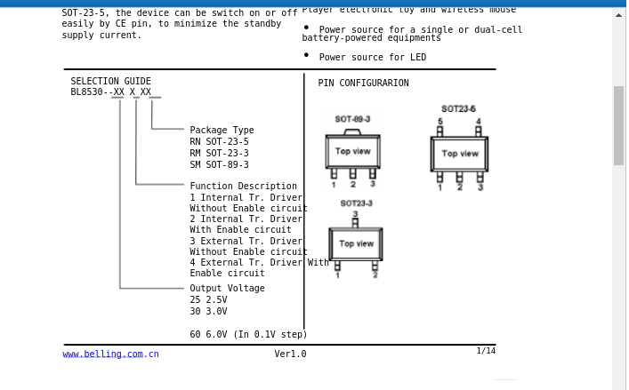
      what is written on the chip? looking at the datasheet there's versions ranging between 3.0 up to 6.0V in 0.1V steps:

      0_1488137189554_upload-755af1ee-fb2d-4c15-9db3-6428fdb49a42

      Orange Pi Plus 2e connected to nrf24 PA via SPI running git-development MySensors gateway, OpenHAB2, mosquitto and MySQL persistence.

      1 Reply Last reply
      0
      • warmaniacW warmaniac

        I measured it on VCC of radio , radio isn't working, alredy tried to add 100 uF capacitor after booster V out , but it not working.

        B Offline
        B Offline
        boozz
        wrote on last edited by
        #5

        @warmaniac

        Are you sure you're not measuring the ripple. These modules are not really known as 'quiet' in terms of stable output voltage, hence the question of the elco.

        Have you tried them 'stand-alone' (no radio) and with a decent load (e.g. a resistor drawing a few milliamps or so).

        BR,

        Boozz

        1 Reply Last reply
        0
        • pansenP Offline
          pansenP Offline
          pansen
          wrote on last edited by
          #6

          true, they actually need some minimum load to function properly but the datasheet does not mention anything about it..

          Orange Pi Plus 2e connected to nrf24 PA via SPI running git-development MySensors gateway, OpenHAB2, mosquitto and MySQL persistence.

          1 Reply Last reply
          0
          • warmaniacW Offline
            warmaniacW Offline
            warmaniac
            wrote on last edited by
            #7

            If I understand correctly, It was measured under load , arduino mini pro 3.3V with nrf24l01+ as door sensor.

            @pansen
            on the chip is written
            LA 3.3
            17B3S

            B 1 Reply Last reply
            0
            • warmaniacW Offline
              warmaniacW Offline
              warmaniac
              wrote on last edited by
              #8

              @pansen

              PIN Configuration :

              SOT-89-3

              1 Reply Last reply
              0
              • warmaniacW warmaniac

                If I understand correctly, It was measured under load , arduino mini pro 3.3V with nrf24l01+ as door sensor.

                @pansen
                on the chip is written
                LA 3.3
                17B3S

                B Offline
                B Offline
                boozz
                wrote on last edited by
                #9

                @warmaniac

                You mean both the pro-mini and nrf24l01+ are fed via this module? In that case you could say that there should be enough load for the power module to get into the 3.3V modus...

                1 Reply Last reply
                0
                • warmaniacW Offline
                  warmaniacW Offline
                  warmaniac
                  wrote on last edited by
                  #10

                  yep , it works well without step up booster , but when I added it, voltage is too high for radio :(

                  B 1 Reply Last reply
                  0
                  • warmaniacW warmaniac

                    yep , it works well without step up booster , but when I added it, voltage is too high for radio :(

                    B Offline
                    B Offline
                    boozz
                    wrote on last edited by
                    #11

                    @warmaniac

                    Strange...

                    Have you considered using a zener (3.3V) as a protection device next to the step-up booster module?

                    BR,

                    Boozz

                    warmaniacW 1 Reply Last reply
                    0
                    • B boozz

                      @warmaniac

                      Strange...

                      Have you considered using a zener (3.3V) as a protection device next to the step-up booster module?

                      BR,

                      Boozz

                      warmaniacW Offline
                      warmaniacW Offline
                      warmaniac
                      wrote on last edited by
                      #12

                      @boozz

                      Could you please send me what you mean ?
                      Something like this ?
                      http://www.ebay.com/itm/New-Zener-Diode-DIP-1-2W-0-5W-2-4V-8-2V-14-Values-Choice-Free-P-P-/262770408086?var=&hash=item3d2e563a96:m:mHD19Qu_1sjnfaWnrsCUbPQ

                      Will not be generating additional energy consumption?

                      B 1 Reply Last reply
                      0
                      • warmaniacW warmaniac

                        @boozz

                        Could you please send me what you mean ?
                        Something like this ?
                        http://www.ebay.com/itm/New-Zener-Diode-DIP-1-2W-0-5W-2-4V-8-2V-14-Values-Choice-Free-P-P-/262770408086?var=&hash=item3d2e563a96:m:mHD19Qu_1sjnfaWnrsCUbPQ

                        Will not be generating additional energy consumption?

                        B Offline
                        B Offline
                        boozz
                        wrote on last edited by
                        #13

                        @warmaniac

                        The zener crossed my mind as a simple but effective way to create a stable 3.3V. It might cost some 'bleeding' amps, maybe you could limit it by using a proper series resistor.

                        See this article for some more details.

                        BR,

                        Boozz

                        1 Reply Last reply
                        0
                        • warmaniacW warmaniac

                          Hi ,

                          I ordered 5 pcs step up boosters from different sellers on ebay.com

                          like here http://www.ebay.com/itm/222350595744?_trksid=p2057872.m2749.l2648&ssPageName=STRK%3AMEBIDX%3AIT

                          and the problem is my output voltage which is from 3,75 - 3,83 Volts, tried many types of new batteries 2xAA input voltage was about 3,10 - 3,20 Volts . How can I solve it to have stable about 3.3 Volts .

                          Thanks much.

                          E Offline
                          E Offline
                          emre299
                          wrote on last edited by
                          #14

                          @warmaniac
                          hello, i am having the same problem. If there is no booster, the mysensors works(full 2xAA), but if there is a booster, it doesn't connect to the network.
                          I connected a capacitor to the bosteer input or output and I used 2 different booster and 2 different nrf but it didn't work.

                          Did you find a way to run mysesors with booster?

                          caniqueC 1 Reply Last reply
                          0
                          • E emre299

                            @warmaniac
                            hello, i am having the same problem. If there is no booster, the mysensors works(full 2xAA), but if there is a booster, it doesn't connect to the network.
                            I connected a capacitor to the bosteer input or output and I used 2 different booster and 2 different nrf but it didn't work.

                            Did you find a way to run mysesors with booster?

                            caniqueC Offline
                            caniqueC Offline
                            canique
                            wrote on last edited by canique
                            #15

                            @emre299 must be something wrong with the booster. Canique Boost module (I run the site selling it) outputs 3.3V no matter if no load is attached or if 50mA or more are drawn from it. It's based on the MCP16251 chip.
                            I guess the ebay modules are based on chinese chips having minimum price as the one and only design goal. Years ago I've bought 2 different ebay modules myself to test them, but they were crap (unnecessary LEDs and even if they were unsoldered the modules had bad efficiency).

                            1 Reply Last reply
                            0
                            • E Offline
                              E Offline
                              emre299
                              wrote on last edited by
                              #16

                              I bought 5 new ones, they didn't work either. I don't understand why it doesn't work Nrf24l01

                              YveauxY skywatchS 2 Replies Last reply
                              0
                              • E emre299

                                I bought 5 new ones, they didn't work either. I don't understand why it doesn't work Nrf24l01

                                YveauxY Offline
                                YveauxY Offline
                                Yveaux
                                Mod
                                wrote on last edited by
                                #17

                                @emre299 the booster likely adds noise to the power line, and it is a known fact that the nrf24 is very sensitive to this.
                                Either filter the noise, or better, get a decent booster.

                                http://yveaux.blogspot.nl

                                1 Reply Last reply
                                1
                                • E emre299

                                  I bought 5 new ones, they didn't work either. I don't understand why it doesn't work Nrf24l01

                                  skywatchS Offline
                                  skywatchS Offline
                                  skywatch
                                  wrote on last edited by skywatch
                                  #18

                                  @emre299 @Yveaux Is right. You could try adding a 47uF or 100uF capacitor across the 3.3V and gnd on the radio module. it is known to help in some cases.

                                  If you have access to an oscilliscope you might be able to see the noise. If it is sharp spikes then a 100nF capacitor can help as before. You may need both in parallel on the radio power connections.

                                  1 Reply Last reply
                                  1
                                  • Y Offline
                                    Y Offline
                                    yetifor
                                    Banned
                                    wrote on last edited by
                                    #19

                                    I would like to step up 3.3V from my power supply with the help of a dc-dc-boost converter to 5V and then I want to draw 500mA by placing a 10 Ohm resistor between the output-pin of the boost-converter and ground.

                                    1 Reply Last reply
                                    0
                                    Reply
                                    • Reply as topic
                                    Log in to reply
                                    • Oldest to Newest
                                    • Newest to Oldest
                                    • Most Votes


                                    17

                                    Online

                                    11.7k

                                    Users

                                    11.2k

                                    Topics

                                    113.0k

                                    Posts


                                    Copyright 2019 TBD   |   Forum Guidelines   |   Privacy Policy   |   Terms of Service
                                    • Login

                                    • Don't have an account? Register

                                    • Login or register to search.
                                    • First post
                                      Last post
                                    0
                                    • MySensors
                                    • OpenHardware.io
                                    • Categories
                                    • Recent
                                    • Tags
                                    • Popular