[SOLVED] Problems with Ethernet Gateway (Arduino Ethernet Shield)
-
I agree with @BulldogLowell . The description that @Anticimex did in the other thread is not easy to understand, at least I could not either. A write-up from someone that has actually done it would be greatly appreciated.
-
I agree with @BulldogLowell . The description that @Anticimex did in the other thread is not easy to understand, at least I could not either. A write-up from someone that has actually done it would be greatly appreciated.
-
exit Arduino ide, download latest Master library 1.4.1
Patch file RF24_config.h (xxxx\MySensors\utility) to enable softspi,
uncomment (remove //) #define SOFTSPI
and change pin numbers as below:
const uint8_t SOFT_SPI_MISO_PIN = 15;
const uint8_t SOFT_SPI_MOSI_PIN = 14;
const uint8_t SOFT_SPI_SCK_PIN = 16;Connecto radio and gateway as per instructions for ethernet gateway except MISO, MOSI and SCK.
These connect as below
radio MOSI to arduino A0,
radio MISO to arduino A1,
radio SCK to arduino A2.start arudino ide 1.5.8, open Ethernet Gateway sketch and amend/add below lines
add this line: #include <DigitalIO.h>
comment UIPEthernet.h (//#include <UIPEthernet.h>)
uncomment Ethernet.h (#include <Ethernet.h>)
and choose IP address
@niccodemi Very good description of what needs to be done. Only addition I would make is that you have to undo the changes you made other than to the gateway sketch when you go back to creating sensors. May be just as easy to reload the library to do that.
-
@Dan-S. said:
I used a standard (cell phone type) 5V power supply and with the AMS1117 (listed in hardware) to knock it down to the 3.3V required by the radio. If your gateway (or sensor) works for a while and then stops and then will start again when plugged back in/rebooted you can almost bet it's a radio power problem (if you are already using soft SPI for your gateway).
Use the latest sketch from the 1.4.1 library for the gateway. The soft SPI stuff is included in the latest library. I just needs to be turned on by some include statement changes in the gateway and RF24_config.h. It requires changes in the radio wiring to the arduino also. I used the instructions provided by Anticimex that are contained in the link I posted above. It's a long thread but the instructions are in there. Probably needs to be broken out as a separate how to posting.
Yeah,
The thread is so long, and after reading through it a few times, it is not possible for me to understand what I need to do to get this working.
I am using the latest library with the Ethernet Gateway sketch on github... but still not working
Here is a photo of my rig, separating the power supply for the radio.
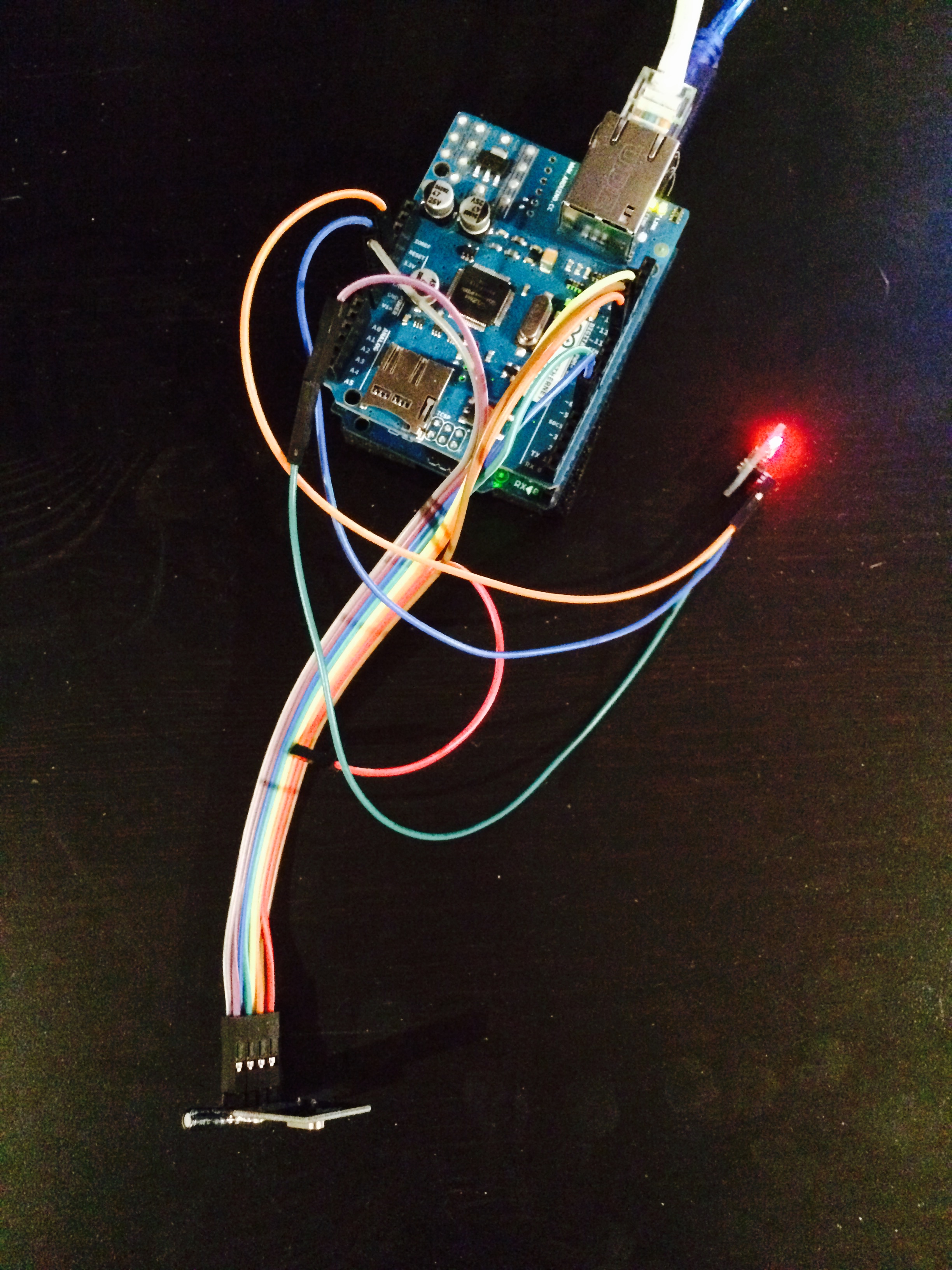
@BulldogLowell You are not using the antenna version but since I am, I used an entirely separate 5 volt wall wart supply to power the radio through the AMS117--did not go through the UNO power as it looks like you did in the pix. Just need to make sure that all the grounds are common if you do like I did, i.e. connect the ground from the separate supply to the UNO/shield ground in addition to the AMS117 and radio ground.
-
exit Arduino ide, download latest Master library 1.4.1
Patch file RF24_config.h (xxxx\MySensors\utility) to enable softspi,
uncomment (remove //) #define SOFTSPI
and change pin numbers as below:
const uint8_t SOFT_SPI_MISO_PIN = 15;
const uint8_t SOFT_SPI_MOSI_PIN = 14;
const uint8_t SOFT_SPI_SCK_PIN = 16;Connecto radio and gateway as per instructions for ethernet gateway except MISO, MOSI and SCK.
These connect as below
radio MOSI to arduino A0,
radio MISO to arduino A1,
radio SCK to arduino A2.start arudino ide 1.5.8, open Ethernet Gateway sketch and amend/add below lines
add this line: #include <DigitalIO.h>
comment UIPEthernet.h (//#include <UIPEthernet.h>)
uncomment Ethernet.h (#include <Ethernet.h>)
and choose IP address
@niccodemi said:
const uint8_t SOFT_SPI_MISO_PIN = 15;
const uint8_t SOFT_SPI_MOSI_PIN = 14;
const uint8_t SOFT_SPI_SCK_PIN = 16;and these are the correct pinouts for my Arduino Ethernet Shield, correct?
This is moving the SPI communication between the Uno and the shield off to another set of pins, and we are leaving the radio pins on hardware SPI?
Thanks!!!!
-
@BulldogLowell You are not using the antenna version but since I am, I used an entirely separate 5 volt wall wart supply to power the radio through the AMS117--did not go through the UNO power as it looks like you did in the pix. Just need to make sure that all the grounds are common if you do like I did, i.e. connect the ground from the separate supply to the UNO/shield ground in addition to the AMS117 and radio ground.
@Dan-S.
Apart from my question above, my only concern is how much power. It occurs to me that the radios attached to my sensor nodes NEVER have this problem, so it make me think that he Ethernet Shield consumes too much power... we got that. Is it the consensus that the power that Uno can provide is not enough to power the Radio and the Ethernet shield?
Thanks for the assistance, it is appreciated. Hope to get there soon!
-
@niccodemi said:
const uint8_t SOFT_SPI_MISO_PIN = 15;
const uint8_t SOFT_SPI_MOSI_PIN = 14;
const uint8_t SOFT_SPI_SCK_PIN = 16;and these are the correct pinouts for my Arduino Ethernet Shield, correct?
This is moving the SPI communication between the Uno and the shield off to another set of pins, and we are leaving the radio pins on hardware SPI?
Thanks!!!!
@BulldogLowell Once you sent the pin definitions in RF24_config.h as you indicated you connect the MOSI, MISO and SCK pins of the radio to A0,A1 and A2 on the Ethernet shield/UNO as niccodemi indicated. The other radio pins remain connected as they were originally.
-
right, completely understood now. i updated my IDE, made all the edits, changed the pins and loaded up my rig.
fingers crossed.
Thanks for everyone's help!
-
right, completely understood now. i updated my IDE, made all the edits, changed the pins and loaded up my rig.
fingers crossed.
Thanks for everyone's help!
-
@BulldogLowell said:
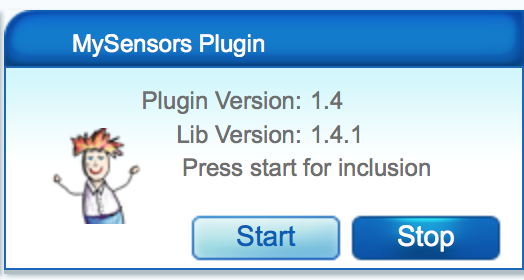
OK... Working fine :)
THANKS to everyone who assisted!!!
UPDATE: 12 hours and working perfectly!
-
Thanks @niccodemi for the detailed how to. Now to only thing unclear to me is if this can be applied on the Ethernet board I have or should I order a new one? I have built a Ethernet GW with a Pro mini and that Ethernet board but I just have not found time to take it in to use and then there was all this about the SPI issue that made me push the task ahead of me.
-
@BulldogLowell , are you using relay actuators with your ethernet gw?
-
@BulldogLowell , are you using relay actuators with your ethernet gw?
I'm not sure I know what you mean... Do you mean are some attached node used as relays?
Gateway still working perfectly...
-
@BulldogLowell yes, node with relay.
-
@BulldogLowell yes, node with relay.
I had... but converted it back to regular non-repeating node.
I had too much trouble with it, but that was before I had this stable Ethernet gateway.
-
I was finally gona tackle my own Ethernet GW but I got stuck at the "0;0;3;0;9;check wires" issue.
I'we checked the wires a couple of times. Tried 4 different power supplies, rewired so that only the radio gets the 3.3v from the LM2937ET-3.3 regulator (arduino Pro mini 3.3 feed with 5v on the raw pin and Ethernet module also gets 5v since it has a AMS1117 onboard). I do have a 47uF cap close to the radio. Tried regular radio module and the PA-LNA module that I was planing on using.
The "check wires" is related to the radio module only right?
Guess I will have to go back to the breadboard to see if I can get it working.
Hello! It looks like you're interested in this conversation, but you don't have an account yet.
Getting fed up of having to scroll through the same posts each visit? When you register for an account, you'll always come back to exactly where you were before, and choose to be notified of new replies (either via email, or push notification). You'll also be able to save bookmarks and upvote posts to show your appreciation to other community members.
With your input, this post could be even better 💗
Register Login