Controlling a 1st gen. LivingColors lamp
-
Having a first generation LivingColors lamp sitting around for a couple a years, mostly doing nothing because the RC batteries are worn out with 6 weeks. I was browsing the internet when a ran into a old project post on knutsel.org describing a LivingColors RC based on Arduino UNO shield, when i decided to give the LC a second life :-)
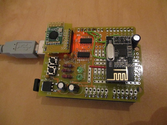
I ordered a build and tested CC2500 shield and mounted a NRF24L01+ Radio module on the board itself. It has plenty of mount space left.
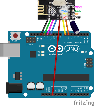
Since the 2500 uses the SPI interface as well i had to use alternative pins for CS and CE. This is how i connected the radio
The build device
For controlling the lamp i'd used vosmont RGB contoller plugin as described in this post
This is the Arduino sketch (please make sure you install the CC2500 library from knutsel.org
/**
 * REVISION HISTORY
 * Version 1.0 - Februari 2016 - Bart Eversdijk
 *
 * DESCRIPTION
 * This sketch provides a LivingColor 1st generation  RGB controller
 *
 * Based on the CC2500 sheild from http://www.knutsel.org/tag/arduino-shield/
 *
 * Optimized for usage with vosmont RGB colorwheel MicsaVerde Vera plug in
 * https://github.com/vosmont/Vera-Plugin-RGBController and http://forum.micasaverde.com/index.php?topic=32613.0
 *
 */
#include <CC2500.h>
#include <ColourConversion.h>
#include <LivingColors.h>
#include <MyTransportNRF24.h>
#include <MyHwATMega328.h>
#include <SPI.h>
#include <MySensor.h>


#define lcMOSI   11    // SPI master data out pin
#define lcMISO   12    // SPI master data in pin
#define lcSCK    13    // SPI clock pin
#define lcCS     10    // SPI slave select pin

#define MY_RF24_CE_PIN  6
#define MY_RF24_CS_PIN  7

// NRFRF24L01 radio driver (set low transmit power by default)
MyTransportNRF24 radio(MY_RF24_CE_PIN, MY_RF24_CS_PIN, RF24_PA_LEVEL_GW);
// Select AtMega328 hardware profile
MyHwATMega328 hw;
// Construct MySensors library
MySensor gw(radio, hw);

LivingColors livcol(lcCS, lcSCK, lcMOSI, lcMISO);

#define lampId  0
unsigned char lamp1[9] = { 0x07, 0x1C, 0x19, 0x10, 0x39, 0xF9, 0x3C, 0xB9, 0x11 }; // Lamp Woonkamer

enum ANIMATIOMODES {RAINBOW=0,RANDONMIZE,FADERGB,FADEMULTICOLR,FLASHCOLOR,LAST_PROGRAM};
char *ANIMATIOMODES_TXT[] = { "RAINBOW","RANDONMIZE","FADERGB","FADEMULTICOLR","FLASHCOLOR" };
byte FADE_RGB_COLOR_MODES[]   = {0b0010,0b0011,0b0100,0b0101,0b1000,0b1001, 0xFF};
byte FADE_MULTI_COLOR_MODES[] = {0b0010,0b0011,0b0110,0b0111,0b0100,0b0101,0b1100,0b1101,0b1000,0b1001,0b1010,0b1011,0xFF};
                          // RRGBU
byte COLOR_WHEEL_MODES[] = {0b0101, 0b0010, 0b1001, 0b0100, 0b0011, 0b1000, 0xFF};

byte ledOffValues[] = {0, 0, 0};
byte rgb_values[]   = {0, 0, 0};

byte speedtable[] = { 0, 400, 100, 20 };
//int speedtable[] = { 0, 50, 25, 2 };
#define NUM_OF_SPEEDS sizeof(speedtable)
#define CHAR2BYTE(x)   (byte)(x > '9' ? (x > 'F' ? (x + 10 - 'a') : (x + 10 - 'A')) : x - '0')

struct
{
   byte values[3];
   byte speedsetting;
   byte mode;
   bool status;
   byte dimlevel;
} rgb = { {0,0,0}, 0, RAINBOW, false, 0};

bool              flashOn      = true;
unsigned long     syscounter   = 0;
unsigned long     lastUpdate   = 0;
bool              newSetting   = false;


void setup() {
    // Initialize library and add callback for incoming messages
    gw.begin(incomingMessage, AUTO, true);
    // Send the sketch version information to the gateway and Controller
    gw.sendSketchInfo("LivingColor", "1.0");

    // Do not present for Vera see forum post: http://forum.mysensors.org/topic/2160/my-mysensors-rgbw-plug-in-has-an-init-problem
    //gw.present(0, S_RGB_LIGHT);

    livcol.init();
    livcol.clearLamps();
    livcol.addLamp(lamp1);

    recallEeprom();
    if (rgb.status) {
       livcol.turnLampOnRGB(lampId, rgb_values[0], rgb_values[1], rgb_values[2]);
    }
    delay(10);

    Serial.println("Init done");
}

void loop()
{
    // Alway process incoming messages whenever possible
    gw.process();

    if (rgb.status && speedtable[rgb.speedsetting] > 0) {
        if ((syscounter % speedtable[rgb.speedsetting]) == 0) {
           switch (rgb.mode)
           {
               case RAINBOW:
                 animateRainbowStep();
                 break;

               case FADERGB:
                 animateFadeColorStep(FADE_RGB_COLOR_MODES);
                 break;

               case FADEMULTICOLR:
//                 animateFadeColorStep(FADE_MULTI_COLOR_MODES);
                 animateColorWheelStep(COLOR_WHEEL_MODES);
                 break;

              case FLASHCOLOR:
                 setLedValues(flashOn ? ledOffValues : rgb.values, false);
                 flashOn = !flashOn;
                 break;

               case RANDONMIZE:
                 rgb_values[0] = (byte)random(0, rgb.dimlevel);
                 rgb_values[1] = (byte)random(0, rgb.dimlevel);
                 rgb_values[2] = (byte)random(0, rgb.dimlevel);
                 setLedValues(rgb_values, false);
                 break;
           }
        }
        delay(rgb.mode == RANDONMIZE || rgb.mode == FLASHCOLOR ? 50 : 1);
    }

    if (newSetting && (lastUpdate + 20000 < syscounter)) {
        // Wait for a couple of seconds be fore actual storing the current setting into EEPROM
        // This will save the EEPROM's life time, when playing around with colors
        Serial.println(" Store EERPOM");
        storeEeprom();
        newSetting = false;
    }

    gw.wait(3);
    syscounter++;
}

void animateRainbowStep()
{
    static float counter = 0;
    float        pi      = 3.14159;
    counter++;
    rgb_values[0] = map(sin(counter/100         )*1000,-1000,1000,0,0xFF);
    rgb_values[1] = map(sin(counter/100 + pi*2/3)*1000,-1000,1000,0,0xFF);
    rgb_values[2] = map(sin(counter/100 + pi*4/3)*1000,-1000,1000,0,0xFF);
    setLedValues(rgb_values, false);
}

void animateFadeColorStep(byte *modes)
{
    static int modecnt = 0;
    if (updateRGBValues(modes[modecnt] >> 1, (modes[modecnt] & 0x1) == 0x1)) {
        modecnt = (modes[modecnt+1] == 0xFF ? 0 : modecnt + 1);
    }
}

void animateColorWheelStep(byte *modes)
{
    static int modecnt = 0;
    for (byte i = 0; i < 3; i++) {
        if ((modes[modecnt] >> (i + 4) & 0x1) == 0x1) {
           rgb_values[i] = 0xFF;
        }
    }
    if (updateRGBValues(modes[modecnt] >> 1, (modes[modecnt] & 0x1) == 0x1)) {
        modecnt = (modes[modecnt+1] == 0xFF ? 0 : modecnt + 1);
    }
}


bool updateRGBValues(byte mode, bool down)
{
    bool endReached = false;
    for (byte i = 0; i < 3; i++) {
        if (((mode >> i) & 0x1) == 0x1) {
           rgb_values[i] += (down ? -1 : 1);
           endReached    |= (down && (rgb_values[i] == 0x00)) || (!down && (rgb_values[i] == 0xFF));
        }
    }
    setLedValues(rgb_values, false);
    return endReached;
}


void incomingMessage(const MyMessage &message) {
    if (message.isAck()) {
        Serial.println("GW acknowledge");
    }

    if (message.type == V_RGB || message.type == V_RGBW) {
	// starting to process the hex code
        const char * hexstring  = message.getString();
        rgb.values[0]    = (CHAR2BYTE(hexstring[0]) << 4) + CHAR2BYTE(hexstring[1]);
        rgb.values[1]    = (CHAR2BYTE(hexstring[2]) << 4) + CHAR2BYTE(hexstring[3]);
        rgb.values[2]    = (CHAR2BYTE(hexstring[4]) << 4) + CHAR2BYTE(hexstring[5]);
        rgb.dimlevel     = (CHAR2BYTE(hexstring[6]) << 4) + CHAR2BYTE(hexstring[7]);

        rgb.speedsetting = 0;  // new color is set stop animation (if is was running)
        if (!rgb.status) {
            // Switch on if the status was off
            rgb.status  = 1;
            livcol.turnLampOnRGB(lampId, rgb.values[0], rgb.values[1], rgb.values[2]);
        }
        setLedValues(rgb.values, true);
        lastUpdate       = syscounter;
        newSetting       = true;
    }

    if (message.type == V_STATUS) {
       if (message.getBool()) {
           Serial.println("ON: Switch to last known color values/or start the last known animation");
           livcol.turnLampOnRGB(lampId, rgb.values[0], rgb.values[1], rgb.values[2]);
       } else {
           Serial.println("OFF: Switch colors off");
           livcol.turnLampOff(lampId);
       }
       rgb.status = message.getBool();
       lastUpdate = syscounter;
       newSetting = true;
    }

    if (message.type == V_VAR1) {
       Serial.println("Set speed and program value");
       const char * newsetting = message.getString();
       rgb.speedsetting = CHAR2BYTE(newsetting[0]);
       byte newmode     = CHAR2BYTE(newsetting[1]);

       if (newmode != rgb.mode) {
           for (byte i = 0; i < 3; i++) {
               rgb_values[i] = 0;
           }
           rgb.mode = newmode;
       }
       if (rgb.speedsetting > 0) {
           rgb.status = true;
       }
       lastUpdate = syscounter;
       newSetting = true;

       Serial.print("Speed:");
       Serial.print(rgb.speedsetting);
       Serial.print(" mode: ");
       Serial.print(rgb.mode);
       Serial.print(" ");
       Serial.println(ANIMATIOMODES_TXT[rgb.mode]);
    }
}


void setLedValues(byte *setrgb, bool show)
{
    static byte oldrgb[] = {0, 0, 0};

    byte newrgb[] = {0, 0, 0};
    newrgb[0] = map(setrgb[0],0,0xFF,0,show?0xFF:rgb.dimlevel);
    newrgb[1] = map(setrgb[1],0,0xFF,0,show?0xFF:rgb.dimlevel);
    newrgb[2] = map(setrgb[2],0,0xFF,0,show?0xFF:rgb.dimlevel);

    bool update = (newrgb[0] != oldrgb[0]) || (newrgb[1] != oldrgb[1]) || (newrgb[2] != oldrgb[2]);
    oldrgb[0] = newrgb[0];
    oldrgb[1] = newrgb[1];
    oldrgb[2] = newrgb[2];

    if (update) {
       livcol.setLampColourRGB(lampId, newrgb[0], newrgb[1], newrgb[2]);
    }
    if (show) {
       Serial.print("Red: " );
       Serial.print(newrgb[0], HEX);
       Serial.print("  Green: " );
       Serial.print(newrgb[1], HEX);
       Serial.print("  Blue: " );
       Serial.print(newrgb[2], HEX);
       Serial.print("  dim level: " );
       Serial.println(rgb.dimlevel, HEX);
    }
}

void storeEeprom()
{
    byte address = 0;
    byte *p = (byte *)&(rgb);
    for (byte i = 0; i < sizeof(rgb); i++) {
       gw.saveState(address++, p[i]);
    }
}

void recallEeprom()
{
    byte address = 0;
    byte *p = (byte *)&(rgb);
    for (byte i = 0; i < sizeof(rgb); i++) {
       p[i] = gw.loadState(address++);
    }
}
And this is some action footage of the end result:
https://youtu.be/7mywMRM3UT4 -
Very intresting : How to give a second life to my old LivingColor !
One question : Is the shield mandatory ? Can I wire the CC2500 and the NRF24 directly on the arduino ?
And finaly, does a chip like this one (https://fr.aliexpress.com/item/Free-Shipping-MD7105-SY-A7105-2-4G-Wireless-Transceiver-Module-3-3V-Better-Than-CC2500-NRF24L01/32714119016.html?isOrigTitle=true) will work with CC2500.h library or should I take one like this one (https://fr.aliexpress.com/item/CC2500-IC-Sans-Fil-RF-metteur-R-cepteur-2-4G-Module-ISM-SPI-D-mo-Code/32674039629.html?isOrigTitle=true) ?
Thanks -
Very intresting : How to give a second life to my old LivingColor !
One question : Is the shield mandatory ? Can I wire the CC2500 and the NRF24 directly on the arduino ?
And finaly, does a chip like this one (https://fr.aliexpress.com/item/Free-Shipping-MD7105-SY-A7105-2-4G-Wireless-Transceiver-Module-3-3V-Better-Than-CC2500-NRF24L01/32714119016.html?isOrigTitle=true) will work with CC2500.h library or should I take one like this one (https://fr.aliexpress.com/item/CC2500-IC-Sans-Fil-RF-metteur-R-cepteur-2-4G-Module-ISM-SPI-D-mo-Code/32674039629.html?isOrigTitle=true) ?
Thanks@mathieu no the shield is not mandatory you can just wire it up yourselves.
But be careful the CC2500 does requires voltage shifting it will brake with TTL level.
Here is the schematicI'm not familiair with this MD7105 replacement.
One general tip for all user or the Livingcolor controller. It took my 2 broken Arduino Uno's to find out why they stopped working after 2 weeks. The onboard 3v3 power convertor is to weak ans will break. So i added my own 3v3 power regulator.
-
Thanks for your precisions.
I was thinking that one of the simplest way to do it can be to simply and directly plug the CC2500 on a 3.3v arduino and power it with an external regulator, but I'm not sure de TTL level will be ok for the NRF24 !
It should also be ok using a 5V arduino and a 4 canal IIC I2C Logic Level Converter Bi-Directionnel Module 5 V à 3.3 V (https://fr.aliexpress.com/item/Free-shipping-1pcs-4-channel-IIC-I2C-Logic-Level-Converter-Bi-Directional-Module-5V-to-3/32670479389.html?isOrigTitle=true). -
I purchased this module:
https://www.aliexpress.com/item/Wireless-Module-CC2500-2-4G-Low-power-Consistency-Stability-Small-Size/32702148262.html?spm=a2g0s.9042311.0.0.L1DfwjThis is the pinout...
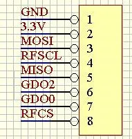
... and I'm in doubt how to wire GDO2, GDO0, RFSC above.
RFCL - SCK (pin 13)?
GDO2 - leave open?
GDO0 - CE (pin 9)?
RFCS - CS(pin 10)?Would you mind to clarify? Thanks!
Hello! It looks like you're interested in this conversation, but you don't have an account yet.
Getting fed up of having to scroll through the same posts each visit? When you register for an account, you'll always come back to exactly where you were before, and choose to be notified of new replies (either via email, or push notification). You'll also be able to save bookmarks and upvote posts to show your appreciation to other community members.
With your input, this post could be even better 💗
Register Login