Board and hardware failures
-
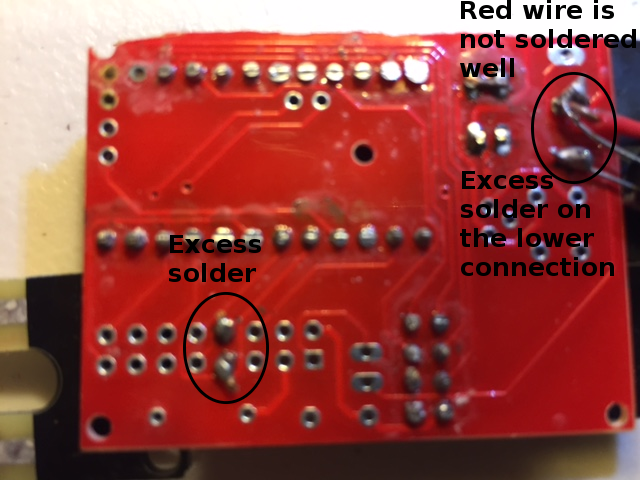
Your pictures from your original post are a bit blurry, but pins 10 and 11 don't appear to come through to the bottom side of the board, and you solder joints don't look the best. Not sure why those pins aren't coming through the bottom side of the board, but that could be a major part of your problem. The traces that connect them to the radio are on the bottom side, so if there is not a good solder connection there, you will most likely have issues. Especially if the through hole plating is damaged in any way.
Suggestions:
- Use some flux and your soldering iron to clean up those solder joints. You may need to use some solder wick, or even a bare piece of copper wire with some flux on it to remove excess solder from your joints if it doesn't wick away with the tip of your iron.
- When soldering, apply heat to both the pad and the lead coming through the hole for a second or two, then apply the solder, then remove the iron. Don't hold the iron on the pads for extended periods as you can damage the pads.
- Use a small chisel tip rather than a conical tip. You will get better heat distribution when soldering. Hold the flat part mostly on the solder pad and touch the protruding wire when soldering.
Here are some examples of good and bad solder joints:
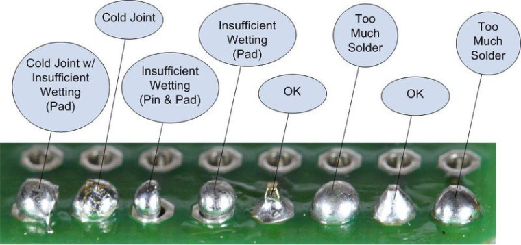
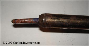
MAKE SURE that the tip of your soldering iron is clean too any time you are going to touch it to the board. A dirty iron tip can cause some of the issues shown above. If your tip looks anything like this, GET A NEW ONE:
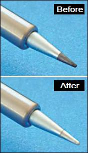
Here is an example of before and after wiping your tip when soldering:
Hope that helps.
-
In the blurred picture it seems more if he trimmed the headers and also some solder in the process.
@gohan said in Board and hardware failures:
In the blurred picture it seems more if he trimmed the headers and also some solder in the process.
Not for 10 and 11, it looks like there are holes in the board in those two spots. The rest of them look like they are cut/trimmed.
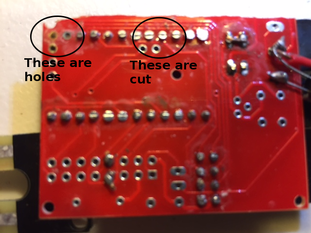
Also, look around pins 10 and 11 and a few other spots on the board. The board is really dirty like excess flux residue. That should be cleaned with alcohol. -
@gohan said in Board and hardware failures:
In the blurred picture it seems more if he trimmed the headers and also some solder in the process.
Not for 10 and 11, it looks like there are holes in the board in those two spots. The rest of them look like they are cut/trimmed.
Also, look around pins 10 and 11 and a few other spots on the board. The board is really dirty like excess flux residue. That should be cleaned with alcohol.@dbemowsk is right here, pins 11 & 12 are not connected to the PCB.
I've had hardare problems with PCBs only with one batch from one maker and after desoldering, if you don't severely overheat the board or apply excessive mechanical force you will not have problem, as they are all electronically tested at the end of the production process and they only send you the boards that pass the test.
And desoldering things like pro mini or nrf24 is a real pain, most of the time you will damage them and just waste your time.
What I do now is I unsolder the parts (mainly atmega, capacitors) on the promini using my hot air gun as it's fast and I can reuse them in SMD projects. But full ProMini and through hole NRF 24 I have given up, not worth the time wasted when you see the price on AliExpress... -
@dbemowsk is right here, pins 11 & 12 are not connected to the PCB.
I've had hardare problems with PCBs only with one batch from one maker and after desoldering, if you don't severely overheat the board or apply excessive mechanical force you will not have problem, as they are all electronically tested at the end of the production process and they only send you the boards that pass the test.
And desoldering things like pro mini or nrf24 is a real pain, most of the time you will damage them and just waste your time.
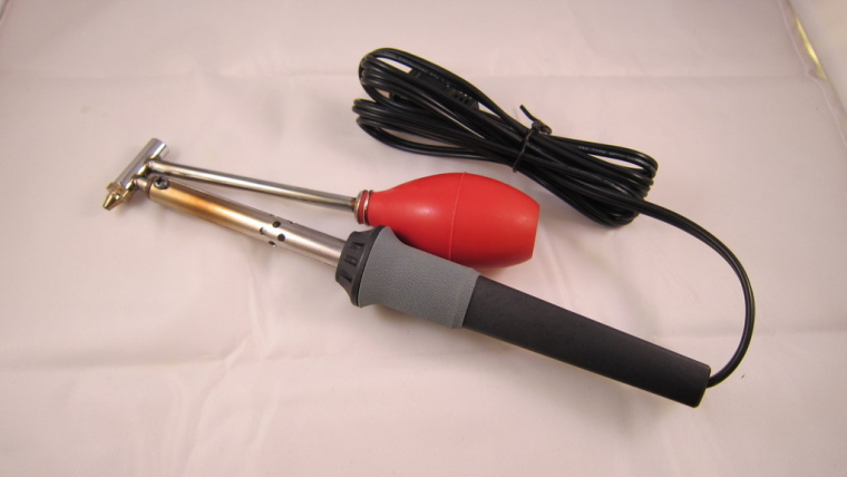
What I do now is I unsolder the parts (mainly atmega, capacitors) on the promini using my hot air gun as it's fast and I can reuse them in SMD projects. But full ProMini and through hole NRF 24 I have given up, not worth the time wasted when you see the price on AliExpress...@Nca78 Years ago I bought this desoldering iron from Radio Shack. This thing works great for thru-hole components as you can heat up the pad and lead with the tip and suck it away right away while it is hot. I have had a few troubles on some things, but overall it has worked well for me.
-
Clever design, a little bulky for my personal taste: I'd have preferred a spring loaded mechanism
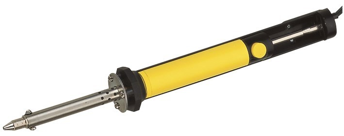
@gohan I have one at work that is a pencil type like the old plunger type solder suckers, but that one doesn't seem to work for crap. What can you expect for $8 bucks. The only reason I bought it was because I knew how well the one I had at home worked, and I thought this might do a similar job.
-
Hello everyone:
I took Gohan's advice and did the continuity tests. On two of the boards I tested, there was a lack of connectivity to pins 10 and 11. (Pins 9,13, and 12 were fine).
These boards were from two different batches.Below is a picture of a board that was actually working for weeks. Then I get the same !TSM:INIT:TSP FAIL failures rolling out. Since this was a plant moisture sensor, I assumed it was because I got some water on it - but maybe not.
On one of the boards, I de-soldered the radio. Then the continuity was even worse. I don't even want to show a picture of it :)
So - does this provide more clues? Any idea on the best way to salvage parts now? I have a feeling the pro-mini is just fine.
Thanks again!
@ileneken3 said in Board and hardware failures:
Since this was a plant moisture sensor, I assumed it was because I got some water on it.
I'll bet on (galvanic) corrosion as a root cause. Protect the pcb or use wires between pcb and sensor.
-
OK, I started over again with the moisture sensor -taking all the advice I got.
- Used female headers, to allow for easily swapping hardware.
- No longer cutting pins on back of the board.
- No longer cutting right side of board off (in case damage is done).
- New soldering iron tip.
- Soldering with a magnifying glass, and being careful.
- Checking continuity.
- Checking pro-mini and radio separately.
- Separating the "fork" so no soil or moisture touches the PCB (avoiding corrosion).
I turned it all on , and got the same !TSM:INIT failures. Just when I was about to throw the board against the wall, I took a shot at shorting the REG (in addition to the BAT). Then everything worked great!
I guess I don't understand why that worked. I figured I'd write myself a spreadsheet, and fill in the combinations. Attached is my start.
Comments/Corrections? -
OK, I started over again with the moisture sensor -taking all the advice I got.
- Used female headers, to allow for easily swapping hardware.
- No longer cutting pins on back of the board.
- No longer cutting right side of board off (in case damage is done).
- New soldering iron tip.
- Soldering with a magnifying glass, and being careful.
- Checking continuity.
- Checking pro-mini and radio separately.
- Separating the "fork" so no soil or moisture touches the PCB (avoiding corrosion).
I turned it all on , and got the same !TSM:INIT failures. Just when I was about to throw the board against the wall, I took a shot at shorting the REG (in addition to the BAT). Then everything worked great!
I guess I don't understand why that worked. I figured I'd write myself a spreadsheet, and fill in the combinations. Attached is my start.
Comments/Corrections?@ileneken3 First and foremostm, don't get discouraged. We are here to help. Can you show us a set of fresh pics of both sides of your board so we can see what's going on? The easy newbie board can have several configurations and depending on how you have things connected with your incoming power will determine what BAT and REG jumpers need to be in place for things to work properly.
-
OK, I started over again with the moisture sensor -taking all the advice I got.
- Used female headers, to allow for easily swapping hardware.
- No longer cutting pins on back of the board.
- No longer cutting right side of board off (in case damage is done).
- New soldering iron tip.
- Soldering with a magnifying glass, and being careful.
- Checking continuity.
- Checking pro-mini and radio separately.
- Separating the "fork" so no soil or moisture touches the PCB (avoiding corrosion).
I turned it all on , and got the same !TSM:INIT failures. Just when I was about to throw the board against the wall, I took a shot at shorting the REG (in addition to the BAT). Then everything worked great!
I guess I don't understand why that worked. I figured I'd write myself a spreadsheet, and fill in the combinations. Attached is my start.
Comments/Corrections?@ileneken3 as @dbemowsk said, there are some configurations you can use which is tested (see openhardware for details). If you have some insight and imagination thought there are probably a 100 different combination you can do... but also 100 different combination that won't work! (100 might be exaggerated but you get the picture).
First rule - the board is not designed to short both bat and reg at the same time.
BAT and REG as dependent on which input you use and if you use a booster/regulator or not.
About your spreadsheet:- Correct! Should work - what kind of problems did you experience?
- Correct! Should work - what kind of problems did you experience?
- Not possible. Using BAT you can not cut the PCB because the trace runs through the booster module. If you dont want to use the booster you can bypass it with a wire but its not possible using 3x5cm cut pcb.
- I dont know, I have to have a schematics because it depends in which input you use and how you put the regulator. This will feed the 3.3v pro mini with 3.7v directly and only regulate the power to the radio.
You always connect your power source to VCC and never RAW - right?
When you had this issue:
I turned it all on , and got the same !TSM:INIT failures. Just when I was about to throw the board against the wall, I took a shot at shorting the REG (in addition to the BAT). Then everything worked great!
What kind of hardware and power supply did you use? Did you use a tested radio (to exclude radio failure).
Another tip is to solder the basic components first (not any sensor or accuator) and test the board with a easy sketch like timeaware sensor. If that works you can continue to include the sensor to exclude its a sensor error.
The easiest way is to follow the guidelines on openhardware or ask what you want to achieve.
-
OK, I started over again with the moisture sensor -taking all the advice I got.
- Used female headers, to allow for easily swapping hardware.
- No longer cutting pins on back of the board.
- No longer cutting right side of board off (in case damage is done).
- New soldering iron tip.
- Soldering with a magnifying glass, and being careful.
- Checking continuity.
- Checking pro-mini and radio separately.
- Separating the "fork" so no soil or moisture touches the PCB (avoiding corrosion).
I turned it all on , and got the same !TSM:INIT failures. Just when I was about to throw the board against the wall, I took a shot at shorting the REG (in addition to the BAT). Then everything worked great!
I guess I don't understand why that worked. I figured I'd write myself a spreadsheet, and fill in the combinations. Attached is my start.
Comments/Corrections?@ileneken3 said in Board and hardware failures:
@gohan
!TSM:INIT failures.TSM INIT means radio was not initialized, in that case only 2 possibilities:
- connection problem with one of the radio pins
- radio doesn't get power (it seems that was the case for you)
-
@ileneken3 as @dbemowsk said, there are some configurations you can use which is tested (see openhardware for details). If you have some insight and imagination thought there are probably a 100 different combination you can do... but also 100 different combination that won't work! (100 might be exaggerated but you get the picture).
First rule - the board is not designed to short both bat and reg at the same time.
BAT and REG as dependent on which input you use and if you use a booster/regulator or not.
About your spreadsheet:- Correct! Should work - what kind of problems did you experience?
- Correct! Should work - what kind of problems did you experience?
- Not possible. Using BAT you can not cut the PCB because the trace runs through the booster module. If you dont want to use the booster you can bypass it with a wire but its not possible using 3x5cm cut pcb.
- I dont know, I have to have a schematics because it depends in which input you use and how you put the regulator. This will feed the 3.3v pro mini with 3.7v directly and only regulate the power to the radio.
You always connect your power source to VCC and never RAW - right?
When you had this issue:
I turned it all on , and got the same !TSM:INIT failures. Just when I was about to throw the board against the wall, I took a shot at shorting the REG (in addition to the BAT). Then everything worked great!
What kind of hardware and power supply did you use? Did you use a tested radio (to exclude radio failure).
Another tip is to solder the basic components first (not any sensor or accuator) and test the board with a easy sketch like timeaware sensor. If that works you can continue to include the sensor to exclude its a sensor error.
The easiest way is to follow the guidelines on openhardware or ask what you want to achieve.
"100 different combinations"
Yes, I meant the spreadsheet to be a list of typical examples - not a comprehensive list. For a "newbie", having a cookbook style recipe is useful.- Works, no problems.
- Works, no problems.
- This is a big surprise. I thought I might have been doing something wrong, but nobody caught that from the pictures I sent! For a plant monitor, where the sensor needs almost no voltage, I didn't think it made sense to use a booster. I also wanted a nice compact device to stick in the plant pot. So, given my "illegal" configuration, I suppose it's no surprise there would be some erratic behavior?
- This works great for me. The board (and most sensors) work fine in the voltage range of a LIPO - only the radio needs to be regulated down to 3.3V. The mcp1700 needs its pins crossed over to work (since the board is designed for a LE33 regulator). A correction to the BOD column would be "2.8V (default)" or "N/A".
I have never used RAW.
Regarding:
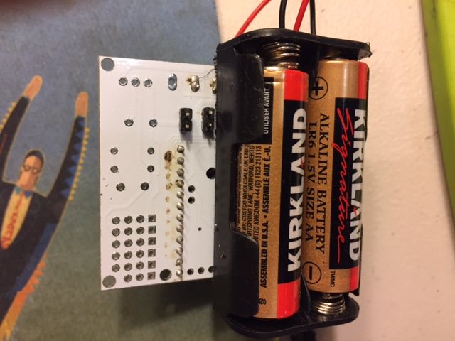
What kind of hardware and power supply did you use? Did you use a tested radio (to exclude radio failure).I used 2 AA , a 3.3V pro mini with no BOD. I tested the radios, and even tried different ones. I can send a picture - but there's nothing interesting with it. So, the existing mystery is: why do I need to short both BAT and REG (which I know now is illegal)? I tried all combinations of shorting/not shorting jumpers - that is the only one that worked.
-
@ileneken3 First and foremostm, don't get discouraged. We are here to help. Can you show us a set of fresh pics of both sides of your board so we can see what's going on? The easy newbie board can have several configurations and depending on how you have things connected with your incoming power will determine what BAT and REG jumpers need to be in place for things to work properly.
@dbemowsk
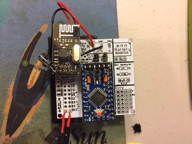
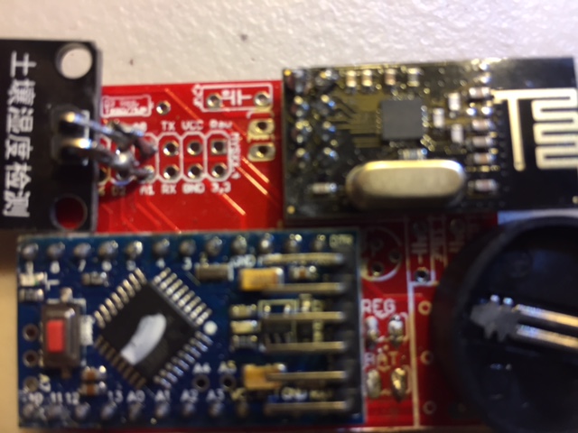
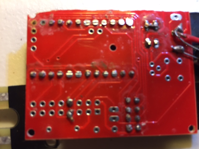
Yes, I appreciate the help! I am hoping others are learning from my adventures. It wouldn't be a fun hobby without a bit of frustration here and there :)I am attaching fresh pictures. The sensor attached is a "fork" for plant moisture monitoring.
-
"100 different combinations"
Yes, I meant the spreadsheet to be a list of typical examples - not a comprehensive list. For a "newbie", having a cookbook style recipe is useful.- Works, no problems.
- Works, no problems.
- This is a big surprise. I thought I might have been doing something wrong, but nobody caught that from the pictures I sent! For a plant monitor, where the sensor needs almost no voltage, I didn't think it made sense to use a booster. I also wanted a nice compact device to stick in the plant pot. So, given my "illegal" configuration, I suppose it's no surprise there would be some erratic behavior?
- This works great for me. The board (and most sensors) work fine in the voltage range of a LIPO - only the radio needs to be regulated down to 3.3V. The mcp1700 needs its pins crossed over to work (since the board is designed for a LE33 regulator). A correction to the BOD column would be "2.8V (default)" or "N/A".
I have never used RAW.
Regarding:
What kind of hardware and power supply did you use? Did you use a tested radio (to exclude radio failure).I used 2 AA , a 3.3V pro mini with no BOD. I tested the radios, and even tried different ones. I can send a picture - but there's nothing interesting with it. So, the existing mystery is: why do I need to short both BAT and REG (which I know now is illegal)? I tried all combinations of shorting/not shorting jumpers - that is the only one that worked.
So, given my "illegal" configuration, I suppose it's no surprise there would be some erratic behavior?
Exactly, there are multiple way for the current to flow.
2 AA , a 3.3V pro mini with no BOD, why do I need to short both BAT and REG (which I know now is illegal)?
Because you shorted BAT first and if you do you have to have a booster or jump this. When you added REG you started feeding the rest of the circuit and it worked. Using BAT you cant cut the PCB or not use the booster.
You said 1 and 2 "Works, no problems."
Du you have it working now, because im not 100% sure what you are trying to achieve.
Hello! It looks like you're interested in this conversation, but you don't have an account yet.
Getting fed up of having to scroll through the same posts each visit? When you register for an account, you'll always come back to exactly where you were before, and choose to be notified of new replies (either via email, or push notification). You'll also be able to save bookmarks and upvote posts to show your appreciation to other community members.
With your input, this post could be even better 💗
Register Login