💬 4-channel switcher/dimmer
-
@tonnerre33,
Thank you for your interest to my device.
The fuse installed to protect the mains 220V from short circuit in the device. Phase need to be connected to the device through a circuit breaker. It will protect from dangerous potential and this allows the lamps to be served safely. But you're right. It would be properly to put the fuse on the phase.Looking at my experience I can say that never had a problem without varistor. But probably in the future I will add it to the board.
@HouseIOT - From my understanding of a varistor: it stops voltage spikes and voltage spikes are the things that causes arcs and therefore shorts on the board. I would include one, i do on my modules anyway.
MySensors 2.1.1
Controller - OpenHAB (Virtual Machine)
Gateway - Arduino Mega MQTT Gateway W5100 -
@HouseIOT - From my understanding of a varistor: it stops voltage spikes and voltage spikes are the things that causes arcs and therefore shorts on the board. I would include one, i do on my modules anyway.
@Samuel235, It is just my first project and it has some weaknesses. But thanks for the comment, I will use it in future.
-
@Samuel235, It is just my first project and it has some weaknesses. But thanks for the comment, I will use it in future.
@HouseIOT said in 💬 4-channel switcher/dimmer:
It is just my first project and it has some weaknesses
It's a very good project for your first. I hope see many another projects from you ;)
-
@Samuel235, It is just my first project and it has some weaknesses. But thanks for the comment, I will use it in future.
@HouseIOT - Not for a second was I point out mistakes to make you feel your first project wasn't good enough dude. Its a very nice project and i'm interested in using it to develop one myself. I'm just giving you my perspective on where to develop this board on your next revision, that is all :)
-
hello,
congrats for your first board :+1:
if i can add a sidenote..
hopefully you have never got problem without varistor. but imho, varistor should be "mandatory", it protects against overvoltage, storms for instance etc. It's not the same as a fuse, and should be always used in combination with a fuse.
Googling will give you a lot of infos i think.
My 2cents if this can help ;) -
I agree with the comments about the varistor, it can certainly help with spikes. But only around 10 times. After that, the varistor will fail. Violently. In Europe, Australia and North America that will not be a big problem, but in countries with a little less reliable grid that could be within a year.
When the MOV fails, it will become a short across the live and neutral, so ALWAYS put your varistor/MOV behind the primary fuse so that that will blow and stop the current across. Otherwise you'll have a nice fire inside the switchbox...little story: a friend of mine lives in the Carribean and they have a sketchy power grid there. One day the fridge was "tingly", so we start searching. Few minutes later: POOF!: magic smokes escapes from the power conditioner for the TV. OK. Something's really wrong here.
So we suspected the wiring because of the corrosive nature of the air there (warm, humid sea breeze). Switch off the power, and start opening switchboxes and outlets (all US 120V system), we start finding all sorts of weird stuff like a circuit that is spliced off, goes into the floor and exits in another box, that is also fed directly from the panel.....
So a few hours later we have checked everything, ripped out some unused wires and checked all connections and switch all back on. Still auchie on the fridge. So after a few minutes unplugging all appliances and socketstrips it was gone!It was a socket strip with net filter. The MOVS had blown and created a short to earth. And since the US system does not use RCDs on all circuits that could go on for a while.
Moral of the story: MOVs can do good. And bad. Use them wisely!
-
@tbowmo said in 💬 4-channel switcher/dimmer:
Would you mind adding the schematics as a PDF file
Yes, I add it soon.
-
@tbowmo said in 💬 4-channel switcher/dimmer:
Would you mind adding the schematics as a PDF file
Yes, I add it soon.
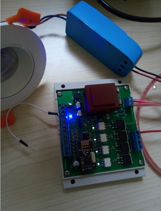
@HouseIOT As a newbie, I did a board completely following you schematics. But unfortunately,not working...
I use the MYsensores-bootloader(8Mhz,V1.5.4!), and I flashed your source ino-code into the board.
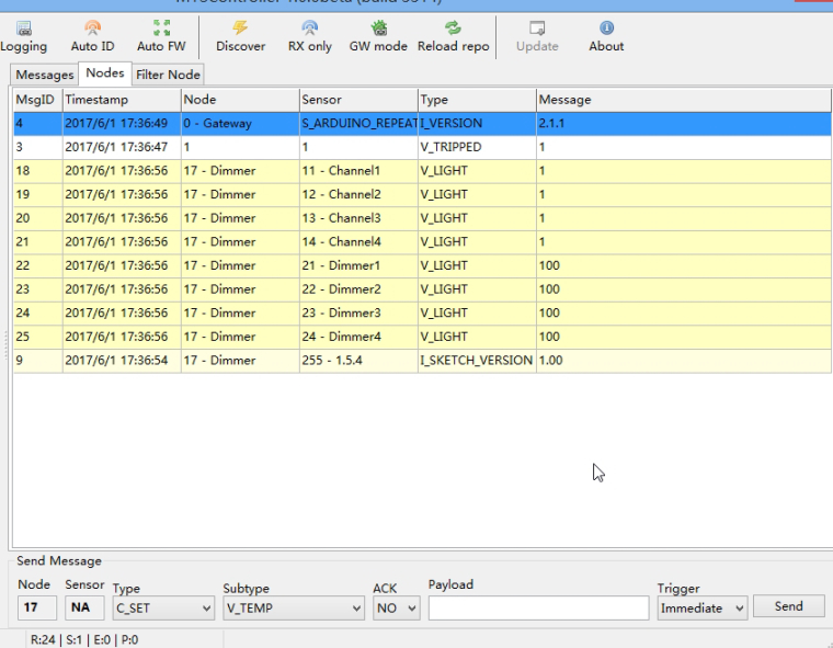
I can see the dimmer in the MYSController(as picture show), but there's no output from the X1.
My gateway is a esp8266 wifi gateway, version is 2.1.1 and it works fine.
PS: After testing job, the circuits of low voltage seems work well, shortcuts x5 and x2, the indicator led show lightness change(OFF, 30 & 100). The problem maybe in the Hi-voltage parts.
PLS help, THANKS a lot !
-
@HouseIOT As a newbie, I did a board completely following you schematics. But unfortunately,not working...
I use the MYsensores-bootloader(8Mhz,V1.5.4!), and I flashed your source ino-code into the board.
I can see the dimmer in the MYSController(as picture show), but there's no output from the X1.
My gateway is a esp8266 wifi gateway, version is 2.1.1 and it works fine.
PS: After testing job, the circuits of low voltage seems work well, shortcuts x5 and x2, the indicator led show lightness change(OFF, 30 & 100). The problem maybe in the Hi-voltage parts.
PLS help, THANKS a lot !
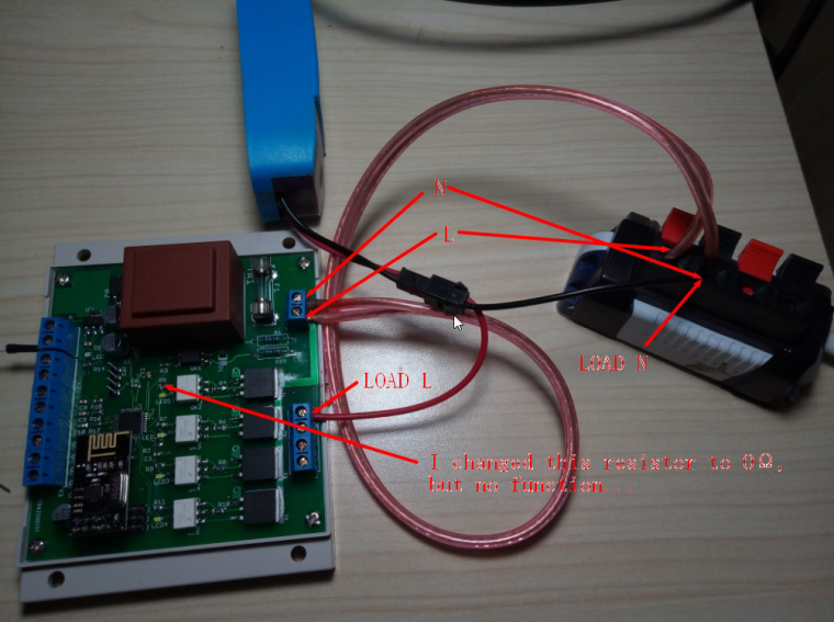
@hhalibo
Check for neutral and phase connected right. I can see only one wire of load connected to X1. Other one must be connected to neutral if on X4.1 is phase. Otherwise try to reduce down to zero R5,7,9,11. May be not open the optocouplers. -
This post is deleted!
@Andrea-Boarino
Hi! It is Sanhe enclosure. I have bought it in Ukraine. -
@hhalibo
Check for neutral and phase connected right. I can see only one wire of load connected to X1. Other one must be connected to neutral if on X4.1 is phase. Otherwise try to reduce down to zero R5,7,9,11. May be not open the optocouplers. -
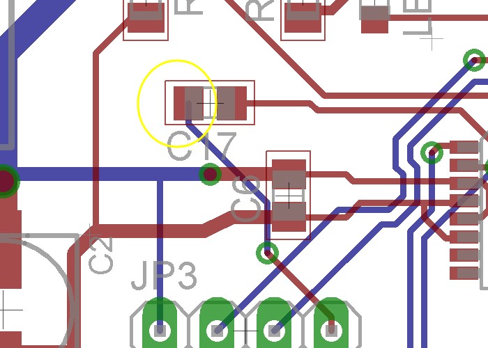
@HouseIOT THANKS for rapid reply!
I changed the resistor(r5) to 0 as pitcture shown, no function...
-
@hhalibo
What supply voltage? 3.3V?..
Usually if properly assembled, there should be no problems. -
@hhalibo
What supply voltage? 3.3V?..
Usually if properly assembled, there should be no problems. -
@hhalibo said in 💬 4-channel switcher/dimmer:
is 220v
My English not so good, sorry. I say about low voltage on Atmega. There should be not less than 3.3v. If it is less then may not be enough current to open the optocoupler.
D1 i not problem. The zero crossing detect works correctly. You see it on LEDs.
-
@hhalibo said in 💬 4-channel switcher/dimmer:
is 220v
My English not so good, sorry. I say about low voltage on Atmega. There should be not less than 3.3v. If it is less then may not be enough current to open the optocoupler.
D1 i not problem. The zero crossing detect works correctly. You see it on LEDs.
@HouseIOT The voltage output from the AMS1117-3.3 is 3.29v, and the voltage of the JP1 (VCC & GND) is 3.29v.
And when the V_PERCENTAGE is 100, the voltage input of the pin1&2 with OK2(3,4,5) is 0.825V.
when V_PERCENTAGE is 30, the voltage input of the pin1&2 with OK2(3,4,5) is 0.25V.
except the voltage input of OK(2,3,4,5) is definitely low,others seems OK.
-
@HouseIOT Sorry to trouble you, i use a mysensors-wifi-gateway with protocol 2.1.1 , and my homeautomation is home-assistant. I can't use your dimmer in my system.
After read the reference, there need to add V-percentage and V-status in the code, as a newbie , I can't do it myself. So I wondered,can you do me a favor?
Thanks a lot.
Hello! It looks like you're interested in this conversation, but you don't have an account yet.
Getting fed up of having to scroll through the same posts each visit? When you register for an account, you'll always come back to exactly where you were before, and choose to be notified of new replies (either via email, or push notification). You'll also be able to save bookmarks and upvote posts to show your appreciation to other community members.
With your input, this post could be even better 💗
Register Login