How to wire battery sensor with battery voltage reports...
-
Ahh i see the instructions for capacitor over tappoint now.
Well I have a dht22 and it needs min 3v but doesnt arduino have a booster if i connect dht22 to VCC? (PRO mini 3.3 8mhz).
@sundberg84 said:
Ahh i see the instructions for capacitor over tappoint now.
Well I have a dht22 and it needs min 3v but doesnt arduino have a booster if i connect dht22 to VCC? (PRO mini 3.3 8mhz).
No, there is no booster on the arduinos, only step-down regulators.
There are other sensors out there (Si7021, SHU21 etc) that are capable of operating down to 1.9V. And the price difference to the DHT22 is not that big.
Anyway, if you stick with the DHT22, then yes.. a booster is necessary to operate from a battery, and also a voltage divider for battery measurement. Or power the arduino with 4xAA to RAW input, and then use the 3.3V output from the arduino to power the radio..
-
well, i have wired it all up and it seems to be almost working, i get humidity and temp from sensor but serial debugging sensor shows "st=fail" on all lines (almost). I think im loosing about 95% of all sent messages.
I have capasitor over Radio., Measuring batteri is current 3.1 volts. Debug shows values from DHT is fine.
Any ideas?
-
What is the distance to the gateway? if it's to big, then it might be the problem. Also, I have seen some reports on the forum, that some have better luck, if they try another radio module (in GW / sensor nodes) So that could also be experimented with.
/ Thomas
-
It Seems to be a power issue-it works better with usb power supply. Ill check more when i get home.
What does st-fail means? Is it some missing/failed axcknowledge message from gw?
-
It Seems to be a power issue-it works better with usb power supply. Ill check more when i get home.
What does st-fail means? Is it some missing/failed axcknowledge message from gw?
@sundberg84 said:
It Seems to be a power issue-it works better with usb power supply. Ill check more when i get home.
What does st-fail means? Is it some missing/failed axcknowledge message from gw?
I think, that it means that the radio didn't receive an acknowledge from the receiving part. There are multiple ACK's in the system. both inter radio (from point to point, which is the one st=ok /st=fail is about). If there are repeaters between the sensor node, and the gw, then this ACK is only for the direct next uplink (repeater).
But also you can ask mysensor to send an ack for each message, this travels across repeaters from GW to sensor (or the other way arround).
So in this case, it means that the radio transmits, but there is no receiver ack'ing that it has heard the broadcast.
-
Ok, tHanks! Will try to move closer to gw and see what happens.
-
Yes - moving it closer to the gateway improves numbers of st=ok but still not 100% (not even close) even if i only have a fem meters between. Needs to check my soldering and wiring.
Thank you for answers - will upload new image when ready and it works.
-
Hi!
Ok, i wanted to share my "sollution" or atleast current setup if someone else in the future has the same problem.
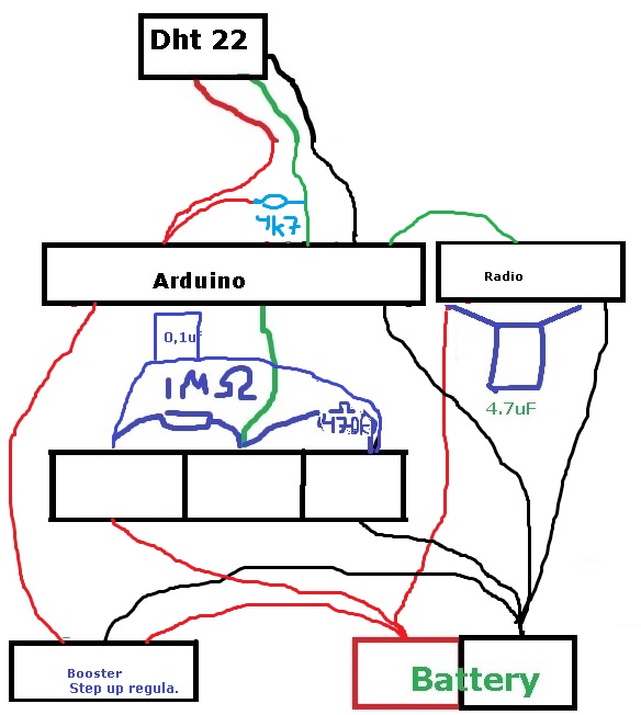
The radio and battery voltage sensor (R1/R2) is not connected to Step up regulator.
Also DHT22 sensor needs atleast 3v to operate so i put the arduino and DHT22 after the voltage regulator.Im sleeping the node for 15min, then sends temp and hum. The Battery status is sent each 8 loop. Now i will have a look how fast the battery is drained. I have not removed the led in the aurdino or step up reg so im guessing quite fast.
I have the radio about 15 meter (1 wall) from the gw - 100% seems to be st=ok.
Any improvement ideas - let me know,
Br
Andreas -
Hi!
Ok, i wanted to share my "sollution" or atleast current setup if someone else in the future has the same problem.
The radio and battery voltage sensor (R1/R2) is not connected to Step up regulator.
Also DHT22 sensor needs atleast 3v to operate so i put the arduino and DHT22 after the voltage regulator.Im sleeping the node for 15min, then sends temp and hum. The Battery status is sent each 8 loop. Now i will have a look how fast the battery is drained. I have not removed the led in the aurdino or step up reg so im guessing quite fast.
I have the radio about 15 meter (1 wall) from the gw - 100% seems to be st=ok.
Any improvement ideas - let me know,
Br
Andreas -
@hek just let me know if you need any additional designers for the homepage :+1: haha
/Andreas
-
The 0,1uF capacitor is usually put in parallell with the 470k. Unless your battery wires are very long or interfered I think it's useless as it is.
-
Hi!
Ok, i wanted to share my "sollution" or atleast current setup if someone else in the future has the same problem.
The radio and battery voltage sensor (R1/R2) is not connected to Step up regulator.
Also DHT22 sensor needs atleast 3v to operate so i put the arduino and DHT22 after the voltage regulator.Im sleeping the node for 15min, then sends temp and hum. The Battery status is sent each 8 loop. Now i will have a look how fast the battery is drained. I have not removed the led in the aurdino or step up reg so im guessing quite fast.
I have the radio about 15 meter (1 wall) from the gw - 100% seems to be st=ok.
Any improvement ideas - let me know,
Br
Andreas@sundberg84 said:
Hi!
Ok, i wanted to share my "sollution" or atleast current setup if someone else in the future has the same problem.
The radio and battery voltage sensor (R1/R2) is not connected to Step up regulator.
Also DHT22 sensor needs atleast 3v to operate so i put the arduino and DHT22 after the voltage regulator.Im sleeping the node for 15min, then sends temp and hum. The Battery status is sent each 8 loop. Now i will have a look how fast the battery is drained. I have not removed the led in the aurdino or step up reg so im guessing quite fast.
I have the radio about 15 meter (1 wall) from the gw - 100% seems to be st=ok.
Any improvement ideas - let me know,
Br
AndreasHi all, I'm newbie with these libraries.
And I'm a bit confused about the picture.
I'm guessing is that the picture still similar with the battery page in build sites. What makes me confused is that resistor position. And also what is the source to measure in the voltage divider? Is it vcc? -
@sundberg84 said:
Hi!
Ok, i wanted to share my "sollution" or atleast current setup if someone else in the future has the same problem.
The radio and battery voltage sensor (R1/R2) is not connected to Step up regulator.
Also DHT22 sensor needs atleast 3v to operate so i put the arduino and DHT22 after the voltage regulator.Im sleeping the node for 15min, then sends temp and hum. The Battery status is sent each 8 loop. Now i will have a look how fast the battery is drained. I have not removed the led in the aurdino or step up reg so im guessing quite fast.
I have the radio about 15 meter (1 wall) from the gw - 100% seems to be st=ok.
Any improvement ideas - let me know,
Br
AndreasHi all, I'm newbie with these libraries.
And I'm a bit confused about the picture.
I'm guessing is that the picture still similar with the battery page in build sites. What makes me confused is that resistor position. And also what is the source to measure in the voltage divider? Is it vcc?@funky81 said:
Hi all, I'm newbie with these libraries.
And I'm a bit confused about the picture.
I'm guessing is that the picture still similar with the battery page in build sites. What makes me confused is that resistor position. And also what is the source to measure in the voltage divider? Is it vcc?Im a newbie as well, also a bit on and off building...
Yes, i have tried to work from the battery build site. I saw you did a own post about this and worked it out.-
I have also tried to take power to the radio from the booster - but this seems to drain the battery very fast, annyone else experienced this?
-
Also i tried to take power to the radio from the arduino - and it works well, is there any downsides with this?
-
Is the radio using any power not used? It seems like the battery last longer with the radio connected to the arduino instread of the battery. When the arduino sleeps - so does the radio i guess, but does the radio sleep any time connected directly to the battery?
-
-
Would be awesome if you made a fritz sketch of this :)
-
Would be awesome if you made a fritz sketch of this :)
@ronnyandre - hehe! That was a while ago :)
I even made a PCB for everyone to use (including full schematics)!Check it out here: https://www.openhardware.io/view/4/EasyNewbie-PCB-for-MySensors
Hello! It looks like you're interested in this conversation, but you don't have an account yet.
Getting fed up of having to scroll through the same posts each visit? When you register for an account, you'll always come back to exactly where you were before, and choose to be notified of new replies (either via email, or push notification). You'll also be able to save bookmarks and upvote posts to show your appreciation to other community members.
With your input, this post could be even better 💗
Register Login