How to wire battery sensor with battery voltage reports...
-
Hi!
I want to wire a sensor node which runs on battery (2xAA)
I have tried to read alot on the forum...It should rapport battery level and have a decouple capacitor to help the radio.
Also i have read on the forum the radio works better if wired directly to the battery?How about a booster? Is it recommended (I have here only for the ardino - should it go to the radio as well?)
Do you think this will work?
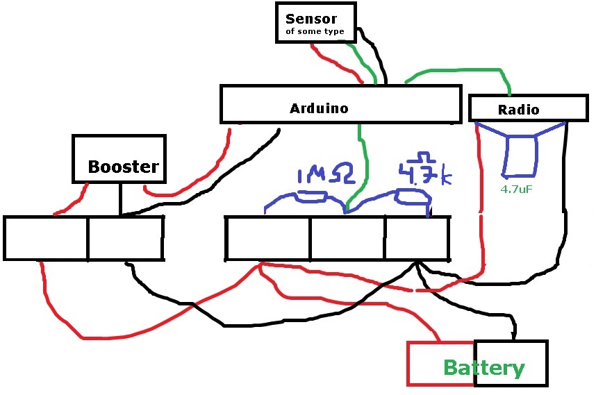
Edit: new setup below - dont wire like this)
(Im not using a breadboard - but will solder it togheter in the squares)Br
Andreas Sundberg(Edit: better picture)
-
It depends on what kind of sensor you want to use. If you are able to find sensors that can operate down to 1.9V, then it's not necessary to use the booster. As both the arduino (8Mhz variant) and the radio can operate down to that supply level.
For a hint on a design, you could take a look at http://forum.mysensors.org/topic/510/minimal-design-thoughts/49Also, for battery voltage measurement, if the arduino is supplied directly from the battery, you can use a method to measure the voltage, where the internal Vref is meassured against the Vcc, and then you calculate Vcc from that. In this case you can skip the 2 resistors for voltage measurements
http://provideyourown.com/2012/secret-arduino-voltmeter-measure-battery-voltage/
-
hi ..
My idea is .. atmega328p can run in 8Mhz down to 2V then you don't need booster..
I use 2xAA .. with big capacitor 100uF with low ESR connected close to nRF24L01+ power pin..
but .. I not tested it .. I do this test .. I try my sensor node with 2V power ..
if failure then sorry .. need booster..about battery voltage measure .. yes .. there are two way .. one is used internal reference 1.1V as reference and resistor divider connect to any analog pin input or .. ( I not tested ) is possible to set reference from AVCC (is connected to VCC) and ADMUX select to 1.1V reference .. and calculate .. then you can measure battery voltage .. I must test it self..
regards.
-
Looks ok, but R2 should be 470k not 4.7k. And a capacitor in parallell to R2 would increase your accuracy. It's also common that you need a pullup resistor between red and green Arduino-Sensor lines.
-
Hi!
Thank you for great answers and links!What kind fo capasitor (in uF) is recommenden for paralell with R2?
I have heard that the radio is sensitive to power ups/downs but it current not volts its sensitive to? - since you say it can opperate down to 1.9V ?
Br
Andreas -
Hi all...
Right now I tested my node and serial gateway ..
ATmega328P DIP 28 , Internal 8Mhz RC oscillator , TIMER2 with 32Khz crystal .
powered 2xAA , 47uF tantalum capacitor .
VBAT measure by resistor divider 1M and 390k with 220nF capacitor .
I try if working down to 2V .. then I setting my regulated power source to 1.9V ..and use serial terminal for debugging message .. I use FT232R with 3.3V setting .. and working .. working good ... serial gateway and sensor node .. I send command to gateway from node also powered from 2V.
I don't know how many it's safe .. but in my solution works..regards
-
Ahh i see the instructions for capacitor over tappoint now.
Well I have a dht22 and it needs min 3v but doesnt arduino have a booster if i connect dht22 to VCC? (PRO mini 3.3 8mhz).
-
Ahh i see the instructions for capacitor over tappoint now.
Well I have a dht22 and it needs min 3v but doesnt arduino have a booster if i connect dht22 to VCC? (PRO mini 3.3 8mhz).
@sundberg84 said:
Ahh i see the instructions for capacitor over tappoint now.
Well I have a dht22 and it needs min 3v but doesnt arduino have a booster if i connect dht22 to VCC? (PRO mini 3.3 8mhz).
No, there is no booster on the arduinos, only step-down regulators.
There are other sensors out there (Si7021, SHU21 etc) that are capable of operating down to 1.9V. And the price difference to the DHT22 is not that big.
Anyway, if you stick with the DHT22, then yes.. a booster is necessary to operate from a battery, and also a voltage divider for battery measurement. Or power the arduino with 4xAA to RAW input, and then use the 3.3V output from the arduino to power the radio..
-
well, i have wired it all up and it seems to be almost working, i get humidity and temp from sensor but serial debugging sensor shows "st=fail" on all lines (almost). I think im loosing about 95% of all sent messages.
I have capasitor over Radio., Measuring batteri is current 3.1 volts. Debug shows values from DHT is fine.
Any ideas?
-
What is the distance to the gateway? if it's to big, then it might be the problem. Also, I have seen some reports on the forum, that some have better luck, if they try another radio module (in GW / sensor nodes) So that could also be experimented with.
/ Thomas
-
It Seems to be a power issue-it works better with usb power supply. Ill check more when i get home.
What does st-fail means? Is it some missing/failed axcknowledge message from gw?
-
It Seems to be a power issue-it works better with usb power supply. Ill check more when i get home.
What does st-fail means? Is it some missing/failed axcknowledge message from gw?
@sundberg84 said:
It Seems to be a power issue-it works better with usb power supply. Ill check more when i get home.
What does st-fail means? Is it some missing/failed axcknowledge message from gw?
I think, that it means that the radio didn't receive an acknowledge from the receiving part. There are multiple ACK's in the system. both inter radio (from point to point, which is the one st=ok /st=fail is about). If there are repeaters between the sensor node, and the gw, then this ACK is only for the direct next uplink (repeater).
But also you can ask mysensor to send an ack for each message, this travels across repeaters from GW to sensor (or the other way arround).
So in this case, it means that the radio transmits, but there is no receiver ack'ing that it has heard the broadcast.
-
Ok, tHanks! Will try to move closer to gw and see what happens.
-
Yes - moving it closer to the gateway improves numbers of st=ok but still not 100% (not even close) even if i only have a fem meters between. Needs to check my soldering and wiring.
Thank you for answers - will upload new image when ready and it works.
-
Hi!
Ok, i wanted to share my "sollution" or atleast current setup if someone else in the future has the same problem.
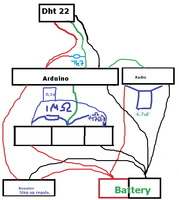
The radio and battery voltage sensor (R1/R2) is not connected to Step up regulator.
Also DHT22 sensor needs atleast 3v to operate so i put the arduino and DHT22 after the voltage regulator.Im sleeping the node for 15min, then sends temp and hum. The Battery status is sent each 8 loop. Now i will have a look how fast the battery is drained. I have not removed the led in the aurdino or step up reg so im guessing quite fast.
I have the radio about 15 meter (1 wall) from the gw - 100% seems to be st=ok.
Any improvement ideas - let me know,
Br
Andreas -
Hi!
Ok, i wanted to share my "sollution" or atleast current setup if someone else in the future has the same problem.
The radio and battery voltage sensor (R1/R2) is not connected to Step up regulator.
Also DHT22 sensor needs atleast 3v to operate so i put the arduino and DHT22 after the voltage regulator.Im sleeping the node for 15min, then sends temp and hum. The Battery status is sent each 8 loop. Now i will have a look how fast the battery is drained. I have not removed the led in the aurdino or step up reg so im guessing quite fast.
I have the radio about 15 meter (1 wall) from the gw - 100% seems to be st=ok.
Any improvement ideas - let me know,
Br
Andreas -
@hek just let me know if you need any additional designers for the homepage :+1: haha
/Andreas
-
The 0,1uF capacitor is usually put in parallell with the 470k. Unless your battery wires are very long or interfered I think it's useless as it is.
Hello! It looks like you're interested in this conversation, but you don't have an account yet.
Getting fed up of having to scroll through the same posts each visit? When you register for an account, you'll always come back to exactly where you were before, and choose to be notified of new replies (either via email, or push notification). You'll also be able to save bookmarks and upvote posts to show your appreciation to other community members.
With your input, this post could be even better 💗
Register Login