nRF5 action!


  • Hero Member

    @mfalkvidd said in nRF5 Bluetooth action!:

    @NeverDie not sure if it applies to this case, but at 18:04 in https://youtu.be/JXQLI-nXqmQ it is mentioned that the chip's identifier needs to be included in some list when the softdevice is compiled (or something along those lines, I am not yet familiar with the vocabulary).

    My understanding (which may be wrong) is that in this context a "softdevice" is a veiled reference to the bluetooth stack and/or related bluetooth code, which at present the mysensors code isn't using. In any case, when I programmed both the adafruit and the sparkfun using the mysensors code, I didn't include a chip identifier in a list, nor any soft devices, and it worked anyway.


  • Hero Member

    I was thinking that maybe the Ebyte module is stuck in some kind of reset mode, but I just now checked pin P0.21 (the reset pin), and it measures high at 3.3v. This is the same as for the Sparkfun board, which I have no trouble programming. Reset is active low.


  • Contest Winner

    @NeverDie said in nRF5 Bluetooth action!:

    My understanding (which may be wrong) is that in this context a "softdevice" is a veiled reference to the bluetooth stack and/or related bluetooth code, which at present the mysensors code isn't using. In any case, when I programmed both the adafruit and the sparkfun using the mysensors code, I didn't include a chip identifier in a list, nor any soft devices, and it worked anyway.

    I haven't tested MySensors with a present SoftDevice. The drivers/NVM code (EEPROM emulation) conflicts with the DFU bootloader.

    It's better to see the SoftDevice as an Operating System providing BLE functionality and some hardware abstraction, while MySensors is directly ported to the hardware.


  • @NeverDie stupid question: did you try to power it NOT from DK board and vise versa?


  • Hero Member

    @Toyman said in nRF5 Bluetooth action!:

    @NeverDie stupid question: did you try to power it NOT from DK board and vise versa?

    Thanks for the suggestion! So far I've tried powering it from a USB 3.3v source (which is how I successfully programmed the adafruit and sparkfun boards), but I'll now try powering it from the DK and see if it makes a difference.

    By the way, I found an alternate way to confirm that the board is using the built-in LDO rather than the DCDC converter. DEC4 is the output of the LDO, and it measures 1.3v (which is also the expected voltage output by the LDO if it were active). DCC is the output of the DCDC converter, and it measures 0.0v. So, empirical confirmation of what you all inferred earlier. 🙂


  • Hero Member

    @Toyman said in nRF5 Bluetooth action!:

    @NeverDie stupid question: did you try to power it NOT from DK board and vise versa?

    Just now tried it, and unfortunately it didn't make a difference. 😞

    The actual text of the error message that I always receive is:

    c:/users/david/appdata/local/arduino15/packages/sandeepmistry/tools/gcc-arm-none-eabi/5_2-2015q4/bin/../lib/gcc/arm-none-eabi/5.2.1/../../../../arm-none-eabi/bin/ld.exe: warning: changing start of section .heap by 4 bytes
    c:/users/david/appdata/local/arduino15/packages/sandeepmistry/tools/gcc-arm-none-eabi/5_2-2015q4/bin/../lib/gcc/arm-none-eabi/5.2.1/../../../../arm-none-eabi/bin/ld.exe: warning: changing start of section .stack_dummy by 4 bytes
    Sketch uses 26932 bytes (5%) of program storage space. Maximum is 524288 bytes.
    Open On-Chip Debugger 0.10.0-dev-00254-g696fc0a (2016-04-10-10:13)
    Licensed under GNU GPL v2
    For bug reports, read
    http://openocd.org/doc/doxygen/bugs.html
    debug_level: 0
    swd
    adapter speed: 10000 kHz
    cortex_m reset_config sysresetreq
    nrf52.cpu: target state: halted
    target halted due to debug-request, current mode: Thread
    xPSR: 0x01000000 pc: 0x000008e4 msp: 0x20000400
    ** Programming Started **
    auto erase enabled
    Error: Cannot erase protected sector at 0x0
    Error: failed erasing sectors 0 to 6
    embedded:startup.tcl:454: Error: ** Programming Failed **
    in procedure 'program'
    in procedure 'program_error' called at file "embedded:startup.tcl", line 510
    at file "embedded:startup.tcl", line 454
    the selected serial port at file "embedded:startup.tcl", line 454
    does not exist or your board is not connected

    So maybe the root of the problem is that I need to do something to enable it to erase the protected sector at 0x0? That seems to be the point after which everything falls apart.


  • Mod

    @NeverDie sorry, the ID doesn't need to be in the softdevice. It needs to be in the code for the black magic probe. Might still not be related though.


  • Mod

    @NeverDie said in nRF5 Bluetooth action!:

    Error: Cannot erase protected sector at 0x0

    Could this be related to the readback protection? The video I linked before recommends issuing "monitor erase_mass" to completely reset the device and any protection.


  • Hero Member

    @mfalkvidd said in nRF5 Bluetooth action!:

    @NeverDie said in nRF5 Bluetooth action!:

    Error: Cannot erase protected sector at 0x0

    Could this be related to the readback protection? The video I linked before recommends issuing "monitor erase_mass" to completely reset the device and any protection.

    Good one! I have a hunch you may have just cracked the problem.

    I see no harm in trying a mass erase before the programming step, so I'll give it a go.


  • Hardware Contributor

    @mfalkvidd said in nRF5 Bluetooth action!:

    @NeverDie said in nRF5 Bluetooth action!:

    Is no one else able to download the files either?

    From the forum, no. From hightail, yes.

    Direct click fails. But if you press Control key while you click, to open in a new tab, then you should be able to download files from the forum 😉


  • Contest Winner

    @mfalkvidd said in nRF5 Bluetooth action!:

    Could this be related to the readback protection? The video I linked before recommends issuing "monitor erase_mass" to completely reset the device and any protection.

    This is a simple sketch for mass erasing a nRF5 MCU. Just compile it with the option a SoftDevice is present, when a SoftDevice is present:

    #include "nrf.h"
    
    void wait_for_ready()
    {
            while (NRF_NVMC->READY == NVMC_READY_READY_Busy) {
            };
    }
    
    
    void setup() {
            // Enable erasing flash
            NRF_NVMC->CONFIG = NVMC_CONFIG_WEN_Een << NVMC_CONFIG_WEN_Pos;
            wait_for_ready();
    
            // Erase Flash and UICR
            NRF_NVMC->ERASEALL = 1;
            wait_for_ready();
    
            // Disable erasing
            NRF_NVMC->CONFIG = NVMC_CONFIG_WEN_Ren << NVMC_CONFIG_WEN_Pos;
            wait_for_ready();
    
    }
    
    void loop() {
    }```

  • Hero Member

    You would think that the programmer device would just do a mass erase as part of its standard procedure, though, so it's a bit odd that it would require me to do it manually. The mass erase that Roger Clark did with his Black Magic Probe seemed nearly instant. I don't have a Black Magic Probe though.

    In any case, I can't use the above sketch to do ia mass erase because it presumes I can already load a sketch onto the target--i.e. it presumes the fundamental problem is solved already.

    What's the preferred way to do a mass erase? I seem to remember seeing a mass erase as an option in one of the Nordic utility softwares, but I don't recall now which one. Anyone happen to know?


  • Hero Member

    Looking further into it, what I may need to first do is UNLOCK the Ebyte module, which appears to be a separate step from mass erasing: https://mcuoneclipse.com/2014/10/05/unlocking-and-erasing-flash-with-segger-j-link/


  • @NeverDie may be some hints here:
    https://learn.adafruit.com/bluefruit-nrf52-feather-learning-guide/flashing-the-bootloader

    And also pay attention to their Adalink tool. The support for nrf52 was added recently.


  • Hero Member

    By switching to a Windows 10 computer, I was able to get J-link working over USB from windows. Then I opened up J-Link Command, which mostly utiizes a command line interface. It turns out that for unlocking, the nRF52836 is not on the list of devices (see below), so I simply then issued a mass erase command, which looks as though it may have worked:

    J-Link>unlock
    Syntax: unlock <DeviceName>
    ---Supported devices---
      LM3Sxxx [<Auto>]
      Kinetis
      EFM32Gxxx
      LPC5460x
    J-Link>erase
    Erasing device (nRF52832_xxAA)...
    J-Link: Flash download: Total time needed: 0.336s (Prepare: 0.064s, Compare: 0.000s, Erase: 0.263s, Program: 0.000s, Verify: 0.000s, Restore: 0.008s)
    Erasing done.
    J-Link>mem 0 100
    00000000 = FF FF FF FF FF FF FF FF FF FF FF FF FF FF FF FF
    00000010 = FF FF FF FF FF FF FF FF FF FF FF FF FF FF FF FF
    00000020 = FF FF FF FF FF FF FF FF FF FF FF FF FF FF FF FF
    00000030 = FF FF FF FF FF FF FF FF FF FF FF FF FF FF FF FF
    00000040 = FF FF FF FF FF FF FF FF FF FF FF FF FF FF FF FF
    00000050 = FF FF FF FF FF FF FF FF FF FF FF FF FF FF FF FF
    00000060 = FF FF FF FF FF FF FF FF FF FF FF FF FF FF FF FF
    00000070 = FF FF FF FF FF FF FF FF FF FF FF FF FF FF FF FF
    00000080 = FF FF FF FF FF FF FF FF FF FF FF FF FF FF FF FF
    00000090 = FF FF FF FF FF FF FF FF FF FF FF FF FF FF FF FF
    000000A0 = FF FF FF FF FF FF FF FF FF FF FF FF FF FF FF FF
    000000B0 = FF FF FF FF FF FF FF FF FF FF FF FF FF FF FF FF
    000000C0 = FF FF FF FF FF FF FF FF FF FF FF FF FF FF FF FF
    000000D0 = FF FF FF FF FF FF FF FF FF FF FF FF FF FF FF FF
    000000E0 = FF FF FF FF FF FF FF FF FF FF FF FF FF FF FF FF
    000000F0 = FF FF FF FF FF FF FF FF FF FF FF FF FF FF FF FF
    J-Link>
    

    🙂


  • Hero Member

    I received the following message from the Ebyte seller:

    Sorry that the two files are incorrect, please just ignore or delete them.
    We will send correct files later.
    
    Thank you!
    

  • Hero Member

    It worked! After doing the above mass erase, the nRF52832 Ebyte Module successfully programmed from the NRF52 DK. I uploaded the mysensors lightsensor sketch, and the serialGateway running on the NRF52 DK is receiving its messages. 🙂

    Many thanks to mfalkvidd for his mass erase suggestion and for his link to the Roger Clark youtube video, which had further mass erase commentary.

    Also, many thanks to d00616 for his excellent guide:
    https://www.openhardware.io/view/376/MySensors-NRF5-Platform
    Without that, I would have been lost on how to set anything up.

    Thanks to everyone else too who made comments and suggestions. This has been a great group effort with a successful outcome. 🙂 🙂 🙂


  • @NeverDie wow!!! Will you write a short tutorial? Is mas erase needed for EVERY time the sketch is uploaded?


  • Hardware Contributor

    That's great news @NeverDie, thank you for your efforts and thank you also to everyone who helped !
    My modules will arrive tomorrow or on Wednesday and you have saved me hours of suffering 😄


  • Hero Member

    Just now did a very quick range test, and the Ebyte nRF52832 module seems roughly comparable to the nRF52 DK for range. i.e. much better than the Adafruit nRF52832 Feather and also much better than the non-amplified nRF24L01+'s. So, whew! What a relief that is. At least for me, that means I won't need to wait for the nRF52840.

    So, now the next question is whether the Ebyte nRF52832 can be made to run in DCDC mode, instead of LDO mode, to make it more suited for battery operation. At the moment, I'm not even sure how big or small a power savings that would equate to. Anyone know?


  • Contest Winner

    @NeverDie said in nRF5 Bluetooth action!:

    So, now the next question is whether the Ebyte nRF52832 can be made to run in DCDC mode, instead of LDO mode, to make it more suited for battery operation. However, at the moment, I'm not even sure how big or small a power savings that would equate to. Anyone know?

    There is no DCDC support for ESB radio at the moment. The DCDC mode is only efficient on high current states, like enabled radio and should only enabled in an defined voltage range.


  • Hero Member

    @Toyman said in nRF5 Bluetooth action!:

    Is mas erase needed for EVERY time the sketch is uploaded?

    Roger Clark says not. I can't say for sure yet, as I haven't yet tried. I think the answer will probably turn out to be that if you aren't doing anything to specifically protect certain flash memory locations after programming it, then you would only need to do it once to undo and erase whatever came on the chip from the factory.


  • Hardware Contributor

    @NeverDie
    like said above DCDC needs to be enabled. Then, the mcu will automatically switch between LDO mode (for light loads) and DCDC mode for higher currents loads like when mcu is wake up, or during radio comms etc.. Can be interesting in some cases.
    in datasheet, DCDC mode can divide by two mcu power consumption. Side effects could be -1dB sensitivity, so it's better to filter well by using two inductors (see ref design)


  • Contest Winner

    I have found a simple way to mass erase the MCU. Select "None" as SoftDevice and use the "Burn Bootloader" function. There is an error generated but the device is erased.


  • Hero Member

    @mtiutiu said in nRF5 Bluetooth action!:

    I'm going to try this one too when I have time wt51822-s4at

    I used your link to order some of those modules just now. They're so small and cheap that they might be nice for simple things.

    With the Ebyte module now working, I'm feeling emboldened again. 🙂


  • Hero Member

    Which nRF52832 pins do I use for the mysensors implementation of UART Tx and Rx on the nRF52832? When I looked in Nordic's nRF52832 datasheet (http://infocenter.nordicsemi.com/pdf/nRF52832_PS_v1.3.pdf), I didn't see any pins specifically assigned/reserved for that purpose.


  • Hardware Contributor

    by default nrf52dk is RX(24) and TX(25).
    for adafruit, i have not installed the board..but you can check in adafruit howto (or in their variant files).

    Peripherals are not fixed, that's a big advantage vs simple 8bits mcu. You define them when doing your design (sometimes it may need some checks in datasheet, depends on mcu).

    So, for your ebyte module your options are:

    • create a new board for the board manager (see variant files) regarding a specific design.
    • or you don't care of this for the moment, and you can simply use nrf52dk board and use the same mapping.
    • or, in the same order, use adafruit board and their mapping (or sparkfun board etc.., no matter, just check their board map pictures )

  • Contest Winner

    @scalz said in nRF5 Bluetooth action!:

    So, for your ebyte module your options are:

    I working on the fourth option, I publish soon:

    • Define the pin mapping in your sketch, then its part of your code

    Like @scalz has written. Place the MCU in your layout and define the pin mapping later. Exceptions are analog pins, comparator pins , NFC pins, reset... The pins are documented in Infocenter: Pin assignments Please look at the "GPIO usage restrictions" chapter too.


  • Hardware Contributor

    @NeverDie

    For the ebyte nrf52832 based modules did you had to wire some external components? Are there some other requirements for it in order to work?

    Thanks.


  • Hero Member

    @mtiutiu said in nRF5 Bluetooth action!:

    @NeverDie

    For the ebyte nrf52832 based modules did you had to wire some external components? Are there some other requirements for it in order to work?

    Thanks.

    For proof of concept purposes, I had just 4 wires connected for programming: PWR, GND, SWDIO, and SWDCLK. After programming for range testing: just PWR and GND. I'll soon be adding UART Tx so that I can also read its serial console output.


  • Hero Member

    @scalz
    Thanks for the explanation. I had been programming it as a "Generic nRF82832," and I don't know what that mapping is. However, I can just as easily pick one of the alternatives you listed, such as the D.K, to get a predictable pin mapping.

    @d00616
    Your idea of having the pin mapping be selectable within the sketch sounds great! A+. I'm really looking forward to that and hope that you can do it soon. It sounds much easier for noobs like me than having to futz about with finding/changing/installing other files, and maybe also making it easier to share with and/or borrow from other makers.


  • Hardware Contributor

    Not related to Bluetooth but @NeverDie did you also receive small antennas and ipx->sma adapters with your modules ?
    I received one for each nrf52 and also one for the pa lna nrf24. I was not expecting them as those modules all have a PCB antenna and ipx is just an option.


  • Hero Member

    @Nca78 said in nRF5 Bluetooth action!:

    did you also receive small antennas and ipx->sma adapters with your modules ?

    Nope.


  • Hero Member

    @scalz said in nRF5 Bluetooth action!:

    nrf52dk is RX(24) and TX(25)

    Hmm.. Where is that defined exactly? I just now tried hooking the Tx(25) of an actual nrf52DK to the Rx pin of a FTDI connector, and GND to GND, but I'm not seeing any output from the nrf52DK, even though I should be. I'm assuming that by 25 you're referring to PO.25 and not pin 25 on the chip?


  • Hero Member

    I googled up this diagram:
    alt text
    Looks as though TX is maybe P0.06. I'll try that....


  • Hero Member

    Confirmed: Pin P0.06 works as Uarte TX on the nRF52 DK. 🙂


  • Hardware Contributor

    @NeverDie yes, you're right 👍 sorry i misread it 😊
    Have fun!


  • Hero Member

    As final confirmation I did re-program the Ebyte module as an nRF52 DK, then connected its P0.06 to the FTDI RX, and, voilà , it worked as expected. @scalz Thanks for the idea! 🙂

    One small caveat: On the Ebyte module, P0.06 doesn't appear on the silkscreen (there's a typo where it's shown as P0.07 instead, resulting in there being two P0.07's on the silkscreen), so just pick the most obvious pin based on the numerical progression (or else consult the datasheet), and it will work.


  • Hero Member

    In lieu of my breakout board, which hasn't yet arrived, I've been attaching wires directly to the module so that I can do more than just sit and wait for the BoB delivery. I'm now doing it this way:
    0_1501085660176_attachments.jpg
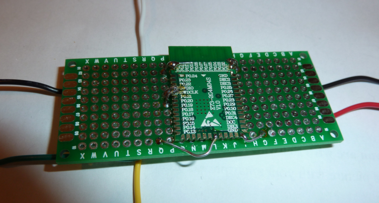
    and although crude it's working much better than just soldering the wire to the module with no mechanical support. Doing it the way pictured, the connections stay connected and don't break loose. 🙂 Ironically, by the time my breakout boards finally do arrive, I may have already learned everything I needed them for.

    I am curious: how are the rest of you handling this issue?

    [Edit: One other alternative: once my 1.27mm pitch generic protoboards arrive, I expect they'll offer up cleaner connection possibilities. At the moment, I'm also waiting for them to arrive from Aliexpress....]


  • Contest Winner

    @NeverDie said in nRF5 Bluetooth action!:

    Your idea of having the pin mapping be selectable within the sketch sounds great! A+. I'm really looking forward to that and hope that you can do it soon.

    With merging this pull request the feature should be available: https://github.com/mysensors/ArduinoBoards/pull/13

    Documentation can be found at https://github.com/mysensors/ArduinoHwNRF5


  • Contest Winner

    @d00616 said in nRF5 Bluetooth action!:

    With merging this pull request the feature should be available: https://github.com/mysensors/ArduinoBoards/pull/13

    Merged. Have fun with board definition in your sketch.


  • Hardware Contributor

    @NeverDie said in nRF5 Bluetooth action!:

    I am curious: how are the rest of you handling this issue?

    Not many solutions, I soldered wires directly to the modules too, I used thin&cheap wires from aliexpress. They are very convenient for this, easy to solder and very soft so not having any constraint on the solder joints when you manipulate them. Then I put module on the side of board with double sided tape and soldered other ends of the wires to a connector.
    0_1501138745943_nrf52_1.jpg
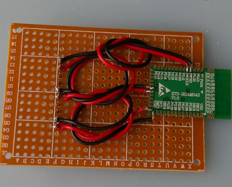
    Then I flip everything and only look at the beautiful side of things 😄
    0_1501138753206_nrf52_2.jpg


  • Hero Member

    @d00616 said in nRF5 Bluetooth action!:

    @d00616 said in nRF5 Bluetooth action!:

    With merging this pull request the feature should be available: https://github.com/mysensors/ArduinoBoards/pull/13

    Merged. Have fun with board definition in your sketch.

    Thanks! By being "merged," does that mean it is now in the regular MySensors development release, and so I should reload a fresh copy of the MySensors development library?

    Also, is this the way I should enable P0.21 as nReset (to enable hardware resets on P0.21), or should I instead be writing 0xFFFF directly to both the PSELRESET[0] and PSELRESET[1] registers to enable that?


  • Mod

    This post is deleted!

  • Contest Winner

    @NeverDie said in nRF5 Bluetooth action!:

    Thanks! By being "merged," does that mean it is now in the regular MySensors development release, and so I should reload a fresh copy of the MySensors development library?

    The Board definition is independed from MySensors core living at https://github.com/mysensors/ArduinoBoards You have to follow the instructions, then you can install the MySensors nRF5 Boards via Arduino Board Manager.

    Also, is this the way I should enable P0.21 as nReset (to enable hardware resets on P0.21), or should I instead be writing 0xFFFF directly to both the PSELRESET[0] and PSELRESET[1] registers to enable that?

    Look into the Tools menu. For nRF52 MCU is a "Reset" menu. Switch it to "Enable"


  • Hero Member

    @d00616
    I got the pin mapping to work, but setting reset enable through the tool menu seems to have no effect. I subsequently drive P0.21 low (all the way to GND even), but no reset happens. Am I doing it wrong? Anyone gotten it to work?


  • Hero Member

    @NeverDie
    I also tried adding a 10K pullup resistor, and no change.

    At the moment I'm unfamiliar with the nRF52 API. What would the code be to set both those reset registers to 0xFFFF? That by itself should enable the reset on P0.21. I could try inserting it into the demo script and see if reset then works.


  • Hero Member

    I guess it wouldn't be that simple, because I just now read that it requires a system reset after writing to those registers: https://devzone.nordicsemi.com/question/157603/can-i-enable-and-disable-nrf52832-reset-pin-when-code-is-running/ for it to take effect.


  • Hardware Contributor

    @NeverDie said in nRF5 Bluetooth action!:

    By switching to a Windows 10 computer, I was able to get J-link working over USB from windows.

    Can you explain the steps you used for that ?
    Did you use a jlink clone or the version included in the DK ?


  • Hardware Contributor

    @Nca78 said in nRF5 Bluetooth action!:

    @NeverDie said in nRF5 Bluetooth action!:

    By switching to a Windows 10 computer, I was able to get J-link working over USB from windows.

    Can you explain the steps you used for that ?
    Did you use a jlink clone or the version included in the DK ?

    Well you can forget about my questions.
    I tried to use the JLink tools to make the mass erase but it didn't want to connect to the module.
    But then I have replaced the driver with Zadig and configured Arduino for NRF5 and it uploaded the LightSensor sketch, I can see it in the log of the controller. No mass erase needed, nor any unlock or related command.
    Just plug and program for me 😄

    I have some strange error messages but I guess they come from (very) dated firmware on my Segger clone

    ** Programming Started **
    auto erase enabled
    Info : nRF51822-QFN48(build code: B00) 512kB Flash
    Warn : not enough working area available(requested 32)
    Warn : no working area available, falling back to slow memory writes
    wrote 28672 bytes from file C:\Users\Nicolas\AppData\Local\Temp\arduino_build_723618/LightSensor.ino.hex in 6.715397s (4.170 KiB/s)
    ** Programming Finished **
    ** Verify Started **
    Warn : not enough working area available(requested 52)
    verified 27432 bytes in 0.279278s (95.923 KiB/s)
    ** Verified OK **
    ** Resetting Target **
    shutdown command invoked
    

  • Hero Member

    @Nca78 said in nRF5 Bluetooth action!:

    Did you use a jlink clone or the version included in the DK ?

    I used the j-link Segger clone to do the mass erase, and then I switched to the DK to do the programming. However, today I was able to do the programming from the Segger clone on the Windows 10 computer, and the setup is less arduous than for programming an external chip using the DK (because with the Segger I didn't have to power the target chip independently during the programming).


  • Hero Member

    So, I guess the way the code would read is:

    1. First check if the reset registers are already properly set.
    2. If so, then just move on to whatever is next.
      If not, then properly set the reset registers and invoke the system reset.

    Apparently a system reset doesn't change the values in the reset registers.

    Of course, none of this would be needed if the reset enable from the tools menu worked, so I'd still prefer to do it that way if at all possible.

    As I indicated earlier, the pin mapping on Rx and Tx did work using @d00616 new technique, so hurray for that. That much was an important victory in itself that's worth celebrating. 🙂


  • Hardware Contributor

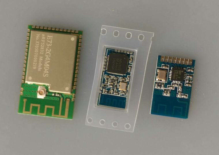
    First nrf51822 module arrived already.
    It's really small, here between an nrf24 SMD and the cdebyte 52832.
    Soldering quality looks better than the pictures on AliExpress.
    0_1501235779537_IMAG1846.jpg


  • Contest Winner

    @NeverDie said in nRF5 Bluetooth action!:

    Apparently a system reset doesn't change the values in the reset registers.

    The "Reset" menu was from my first approach creating user manageable boards for arduino-nrf5. I haven' tested it. With the reset menu I set the "-DCONFIG_GPIO_AS_PINRESET" option. This option should be processed in "cores/nRF5/SDK/components/toolchain/system_nrf52.c". If not the SystemInit() function is not processed in the startup code. This is a problem handling the chip errata. I have not time to check this at the moment.

    Here is a PR which want to enable reset as default: https://github.com/sandeepmistry/arduino-nRF5/pull/91


  • Hero Member

    Maybe the reset pin problem is hardware related? I say that because if I program the Ebyte module as a Nordic nRF52832 DK board, it still has the same issue. In contrast, the reset button on the actual nRF52832 DK board does work as expected.


  • Hero Member

    I've confirmed that connecting P0.21 to GND and then removing it again on the Nordic nRF52832 DK does act as a reset. So, at the moment I have no idea why doing so on the Ebyte nRF52832 that's been programmed to think it's an Nordic nRF52832 DK doesn't do the same. There must be some hardware difference, right?


  • Hero Member

    I've confirmed that on both the Ebyte Module and on the Nordic nRF52832 DK, there is continuity between the P0.21 pin on the chip and the P0.21 pin on the board pinout. So, there must be some other factor that accounts for the difference.


  • Hero Member

    Making no headway on the reset topic, so for now I'm going to punt and move on to other things.


  • Hero Member

    Success! I received some of these modules:
    https://www.aliexpress.com/item/nRF52832-Bluetooth-4-1-BLE-Module-M4-Transparent-Transmission-SMA-512K-FLASH-64K-RAM-pass-through/32798522093.html?spm=2114.search0104.3.10.osbQHP&ws_ab_test=searchweb0_0,searchweb201602_5_10152_10065_10151_10068_10130_10084_10083_10119_10080_10307_10082_10081_10110_10178_10137_10111_10060_10112_10113_10155_10114_10154_10056_10055_10054_10310_10312_10059_100031_10099_10078_10079_10103_10073_10102_10120_10052_10053_10142_10107_10050_10051-10120,searchweb201603_2,ppcSwitch_5&btsid=b9a0c3cb-cc2a-4254-b24f-94136c73def6&algo_expid=2a71f70b-4929-43a5-887a-2f7263250568-1&algo_pvid=2a71f70b-4929-43a5-887a-2f7263250568
    which I immediately programmed using the nRF52832 DK. This time, there was no need to first mass erase. Furthermore, this time P0.21 does indeed reset the module after it is pulled to ground and then released.

    So, from this I conclude there must be something peculiar to the Ebyte modules which prevents their resetting using P0.21.

    It's nice to have different modules to compare amongst. 🙂


  • Mod

    @NeverDie gotta catch them all 🙂


  • Hero Member


  • Hero Member

    Anyone have a good sketch for measuring the battery supplied voltage on an nRF52? Some of the concepts from the old atmega328p may apply, but the specifics are going to be different, I'm sure.


  • Check on adafruits feather reference they use two resistors as a voltage divider for that simple and effective.


  • Hero Member

    @Mike_Lemo said in nRF5 Bluetooth action!:

    Check on adafruits feather reference they use two resistors as a voltage divider for that simple and effective.

    I'm not finding it. Do you have a link?


  • @NeverDie https://learn.adafruit.com/assets/39913

    Top right corner of the schematic.


  • @NeverDie but a much better but more expensive solution would be a lipo fuel guage from spark fun they use a Max chip for that.


  • Hardware Contributor

    If supplied with less than 3.6V you can do it with ADC, 1.2V voltage reference and 1/3 prescaling.
    But I've only looked at the theory yet.

    Rules are Vdd+0.3V max at the pin, and max 2.4V as input of ADC (after prescaling)


  • Hero Member

    Well, as you all know, on the atmega328p you can read the 1.1v gap voltage using the battery voltage as the reference voltage, by doing analogRead(A0), and from just that one measurement then calculate the battery voltage by doing a little bit of math. So, I'm just wondering what the code is to do the equivalent of that (using 1.2v instead of 1.1v) on the nRF52832.


  • Contest Winner

    @Nca78 said in nRF5 Bluetooth action!:

    If supplied with less than 3.6V you can do it with ADC, 1.2V voltage reference and 1/3 prescaling.
    But I've only looked at the theory yet.

    For this, you can use the implemented hwCPUVoltage() function. Reading the voltage costs nRF51: 260µA/20µs | nRF52: 700µA/3µs


  • Hero Member

    @d00616 said in nRF5 Bluetooth action!:

    hwCPUVoltage()

    I'm finally installing Visual Micro, because I hope it will help me quickly find where all these functions are defined. With all these new layers, the Arduino IDE is just no longer cutting it.


  • Hero Member

    LOL. Well, Visual Micro found it alright, but just in the wrong place. It found it in MyHwAVR.cpp


  • Hardware Contributor

    @NeverDie said in nRF5 Bluetooth action!:

    @d00616 said in nRF5 Bluetooth action!:

    hwCPUVoltage()

    I'm finally installing Visual Micro, because I hope it will help me quickly find where all these functions are defined. With all these new layers, the Arduino IDE is just no longer cutting it.

    good choice 👍
    for nrf5, the function is located in MyHwNRF5.cpp


  • Hero Member

    @d00616 said in nRF5 Bluetooth action!:

    For this, you can use the implemented hwCPUVoltage() function.

    I tried this function call on an nRF52 DK, and it seems to work. I then tried it on an Ebyte module, treated as an nRF52 DK "board", and it reported zero voltage. So, probably I just need to do a pin mapping so that it reads the voltage on the proper pin. But which pin/mapping would it be? I thought that Vcc wouldn't really be mappable to anything but Vcc. I guess whichever analog pin (if that's what it is?) is connected to Vcc on the nRF52 DK is the pin I need to find and re-map to its equivalent pin on the Ebyte module. Hmmm.... I'll have to look into which one that would be.


  • Hero Member

    Actually, something different may be going on. Here's the function definition:

    uint16_t hwCPUVoltage()
    {
    	// VDD is prescaled 1/3 and compared with the internal 1.2V reference
    	Serial.println("Inside hwCPUVoltage function.");
    #if defined(NRF_ADC)
        Serial.println("This is an NRF_ADC.");
    	// NRF51:
    	// Sampling is done with lowest resolution to minimize the time
    	// 20uS@260uA
    
    	// Concurrent ressource: disable
    	uint32_t lpcomp_enabled = NRF_LPCOMP->ENABLE;
    	NRF_LPCOMP->ENABLE = 0;
    
    	// Enable and configure ADC
    	NRF_ADC->ENABLE = 1;
    	NRF_ADC->CONFIG = (ADC_CONFIG_EXTREFSEL_None << ADC_CONFIG_EXTREFSEL_Pos) |
    	                  (ADC_CONFIG_PSEL_Disabled << ADC_CONFIG_PSEL_Pos) |
    	                  (ADC_CONFIG_REFSEL_VBG << ADC_CONFIG_REFSEL_Pos) |
    	                  (ADC_CONFIG_INPSEL_SupplyOneThirdPrescaling << ADC_CONFIG_INPSEL_Pos) |
    	                  (ADC_CONFIG_RES_8bit << ADC_CONFIG_RES_Pos);
    	NRF_ADC->EVENTS_END = 0;
    	NRF_ADC->TASKS_START = 1;
    	while(!NRF_ADC->EVENTS_END);
    	NRF_ADC->EVENTS_END = 0;
    	int32_t sample = (int32_t)NRF_ADC->RESULT;
    	NRF_ADC->TASKS_STOP = 1;
    	NRF_ADC->ENABLE = 0;
    
    	// Restore LPCOMP state
    	NRF_LPCOMP->ENABLE = lpcomp_enabled;
    
    	return (sample*3600)/255;
    
    #elif defined(NRF_SAADC)
    	// NRF52:
    	// Sampling time 3uS@700uA
    	Serial.println("This is an NRF_SAADC.");
    	int32_t sample;
    	NRF_SAADC->ENABLE = SAADC_ENABLE_ENABLE_Enabled << SAADC_ENABLE_ENABLE_Pos;
    	NRF_SAADC->RESOLUTION = SAADC_RESOLUTION_VAL_8bit << SAADC_RESOLUTION_VAL_Pos;
    	NRF_SAADC->CH[0].PSELP = SAADC_CH_PSELP_PSELP_VDD << SAADC_CH_PSELP_PSELP_Pos;
    	NRF_SAADC->CH[0].CONFIG = (SAADC_CH_CONFIG_BURST_Disabled << SAADC_CH_CONFIG_BURST_Pos) |
    	                          (SAADC_CH_CONFIG_MODE_SE << SAADC_CH_CONFIG_MODE_Pos) |
    	                          (SAADC_CH_CONFIG_TACQ_3us << SAADC_CH_CONFIG_TACQ_Pos) |
    	                          (SAADC_CH_CONFIG_REFSEL_Internal << SAADC_CH_CONFIG_REFSEL_Pos) |
    	                          (SAADC_CH_CONFIG_GAIN_Gain1_6 << SAADC_CH_CONFIG_GAIN_Pos) |
    	                          (SAADC_CH_CONFIG_RESN_Bypass << SAADC_CH_CONFIG_RESN_Pos) |
    	                          (SAADC_CH_CONFIG_RESP_Bypass << SAADC_CH_CONFIG_RESP_Pos);
    	NRF_SAADC->OVERSAMPLE = SAADC_OVERSAMPLE_OVERSAMPLE_Bypass << SAADC_OVERSAMPLE_OVERSAMPLE_Pos;
    	NRF_SAADC->SAMPLERATE = SAADC_SAMPLERATE_MODE_Task << SAADC_SAMPLERATE_MODE_Pos;
    	NRF_SAADC->RESULT.MAXCNT = 1;
    	NRF_SAADC->RESULT.PTR = (uint32_t)&sample;
    
    	NRF_SAADC->EVENTS_STARTED = 0;
    	NRF_SAADC->TASKS_START = 1;
    	while (!NRF_SAADC->EVENTS_STARTED);
    	NRF_SAADC->EVENTS_STARTED = 0;
    
    	NRF_SAADC->EVENTS_END = 0;
    	NRF_SAADC->TASKS_SAMPLE = 1;
    	while (!NRF_SAADC->EVENTS_END);
    	NRF_SAADC->EVENTS_END = 0;
    
    	NRF_SAADC->EVENTS_STOPPED = 0;
    	NRF_SAADC->TASKS_STOP = 1;
    	while (!NRF_SAADC->EVENTS_STOPPED);
    	NRF_SAADC->EVENTS_STOPPED = 1;
    
    	NRF_SAADC->ENABLE = (SAADC_ENABLE_ENABLE_Disabled << SAADC_ENABLE_ENABLE_Pos);
    
    	return (sample*3600)/255;
    #else
    	Serial.println("Unknown MCU!!");
    	// unknown MCU
    	return 0;
    #endif
    }
    

    One, perhaps likely, theory would be that it doesn't recognize the MCU, which would explain why it returns the value of zero. Well, to debug that, I added the Serial.println(...) statements into the library code (see above) in an attempt to see which of the if-else branches is being taken, but none of the Serial.println(...)'s were printed! Here's a sample of the output from the Ebyte Module:

    332641 TSF:MSG:SEND,255-255-255-255,s=255,c=3,t=7,pt=0,l=0,sg=0,ft=0,st=OK:
    332968 TSF:MSG:READ,0-0-255,s=255,c=3,t=8,pt=1,l=1,sg=0:0
    332973 TSF:MSG:FPAR OK,ID=0,D=1
    334649 TSM:FPAR:OK
    334650 TSM:ID
    334651 TSM:ID:REQ
    334654 TSF:MSG:SEND,255-255-0-0,s=59,c=3,t=3,pt=0,l=0,sg=0,ft=0,st=OK:
    336662 TSM:ID
    336663 TSM:ID:REQ
    336665 TSF:MSG:SEND,255-255-0-0,s=23,c=3,t=3,pt=0,l=0,sg=0,ft=0,st=OK:
    338673 TSM:ID
    338674 TSM:ID:REQ
    338676 TSF:MSG:SEND,255-255-0-0,s=242,c=3,t=3,pt=0,l=0,sg=0,ft=0,st=OK:
    340684 TSM:ID
    340685 TSM:ID:REQ
    340687 TSF:MSG:SEND,255-255-0-0,s=205,c=3,t=3,pt=0,l=0,sg=0,ft=0,st=OK:
    342695 !TSM:ID:FAIL
    342696 TSM:FAIL:CNT=7
    342698 TSM:FAIL:DIS
    342700 TSF:TDI:TSL
    402703 TSM:FAIL:RE-INIT
    402705 TSM:INIT
    402706 TSM:INIT:TSP OK
    402708 TSM:FPAR
    402711 TSF:MSG:SEND,255-255-255-255,s=255,c=3,t=7,pt=0,l=0,sg=0,ft=0,st=OK:
    403472 TSF:MSG:READ,0-0-255,s=255,c=3,t=8,pt=1,l=1,sg=0:0
    403478 TSF:MSG:FPAR OK,ID=0,D=1
    404719 TSM:FPAR:OK
    404720 TSM:ID
    404721 TSM:ID:REQ
    404724 TSF:MSG:SEND,255-255-0-0,s=241,c=3,t=3,pt=0,l=0,sg=0,ft=0,st=OK:
    406732 TSM:ID
    406733 TSM:ID:REQ
    406735 TSF:MSG:SEND,255-255-0-0,s=205,c=3,t=3,pt=0,l=0,sg=0,ft=0,st=OK:
    408743 TSM:ID
    408744 TSM:ID:REQ
    408747 TSF:MSG:SEND,255-255-0-0,s=168,c=3,t=3,pt=0,l=0,sg=0,ft=0,st=OK:
    410754 TSM:ID
    410755 TSM:ID:REQ
    410757 TSF:MSG:SEND,255-255-0-0,s=131,c=3,t=3,pt=0,l=0,sg=0,ft=0,st=OK:
    412765 !TSM:ID:FAIL
    412766 TSM:FAIL:CNT=7
    412768 TSM:FAIL:DIS
    412770 TSF:TDI:TSL
    472773 TSM:FAIL:RE-INIT
    472775 TSM:INIT
    472776 TSM:INIT:TSP OK
    472778 TSM:FPAR
    472781 TSF:MSG:SEND,255-255-255-255,s=255,c=3,t=7,pt=0,l=0,sg=0,ft=0,st=OK:
    472955 TSF:MSG:READ,0-0-255,s=255,c=3,t=8,pt=1,l=1,sg=0:0
    472960 TSF:MSG:FPAR OK,ID=0,D=1
    474789 TSM:FPAR:OK
    474790 TSM:ID
    474791 TSM:ID:REQ
    474794 TSF:MSG:SEND,255-255-0-0,s=167,c=3,t=3,pt=0,l=0,sg=0,ft=0,st=OK:
    476802 TSM:ID
    476803 TSM:ID:REQ
    476805 TSF:MSG:SEND,255-255-0-0,s=131,c=3,t=3,pt=0,l=0,sg=0,ft=0,st=OK:
    478813 TSM:ID
    478814 TSM:ID:REQ
    478816 TSF:MSG:SEND,255-255-0-0,s=94,c=3,t=3,pt=0,l=0,sg=0,ft=0,st=OK:
    480824 TSM:ID
    480825 TSM:ID:REQ
    480827 TSF:MSG:SEND,255-255-0-0,s=57,c=3,t=3,pt=0,l=0,sg=0,ft=0,st=OK:
    482835 !TSM:ID:FAIL
    482836 TSM:FAIL:CNT=7
    482838 TSM:FAIL:DIS
    482840 TSF:TDI:TSL
    

    I'm not quite sure how to interpret that, but pretty clearly it doesn't contain the println's that I was expecting.

    Any theories as to what's going on?


  • Hero Member

    Bracketing that and setting it aside, I do now notice this line in the BatteryPoweredSensor demo sketch:

    int BATTERY_SENSE_PIN = A0;  // select the input pin for the battery sense point
    

    So, if I map that A0 in the sketch to the A0 of the Ebyte Module, then maybe (hopefully) the voltage measurement will work on the Ebyte Module. I'll give it a try.


  • Hero Member

    Unfortunately, after I add:

    #include <mySensors.h>
    

    the locus of control goes somewhere else (I guess the gateway or something?). Anyhow, it makes this very hard to debug.

    For instance, the pin of interest is PIN_AIN0. I can't find where it's defined, and I can't print out its value either, because of this locus of control issue.

    Anyhow, I think I may wait for others to get up and running with their modules, and start facing the same issues. Maybe then we can help each other figure this stuff out.


  • Contest Winner

    @NeverDie I don't know why the println() doesn't work. There is an "DEBUG_OUTPUT(x, ##VA_ARGS)" macro, you can use when debug is enabled.

    NRF_ADC is the nRF51 ADC and NRF_SAADC is the ADC of the nRF52. They are defined when "nrf.h" is included.

    What board type have use used for your tests?


  • Hero Member

    @d00616 said in nRF5 Bluetooth action!:

    What board type have use used for your tests?

    The nRF52832 Ebyte Module.


  • @NeverDie VS Code with the Arduino Extension is your friend.


  • Hero Member

    @d00616 said in nRF5 Bluetooth action!:

    What board type have use used for your tests?

    I just re-read your question and realized you were asking something else than the question that I answered above.

    Answer: nRF52 DK is the board type, because I wired directly to P0.06 as its Tx pin on the Ebyte nRF52832 Module.


  • Hero Member

    @Terrence said in nRF5 Bluetooth action!:

    VS Code with the Arduino Extension is your friend.

    I'll try that. Maybe it will be a little less of a learning curve than Visual Micro yet still do what I need.


  • Hero Member

    I just now did a brute force hack of the MySensors BatteryPoweredSensor sketch, where I copied and renamed the hwCPUVoltage function from the library and then called it from within a tight loop so that I never lose the locus of control. It worked!

    /**
     * The MySensors Arduino library handles the wireless radio link and protocol
     * between your home built sensors/actuators and HA controller of choice.
     * The sensors forms a self healing radio network with optional repeaters. Each
     * repeater and gateway builds a routing tables in EEPROM which keeps track of the
     * network topology allowing messages to be routed to nodes.
     *
     * Created by Henrik Ekblad <henrik.ekblad@mysensors.org>
     * Copyright (C) 2013-2015 Sensnology AB
     * Full contributor list: https://github.com/mysensors/Arduino/graphs/contributors
     *
     * Documentation: http://www.mysensors.org
     * Support Forum: http://forum.mysensors.org
     *
     * This program is free software; you can redistribute it and/or
     * modify it under the terms of the GNU General Public License
     * version 2 as published by the Free Software Foundation.
     *
     *******************************
     *
     * DESCRIPTION
     *
     * This is an example that demonstrates how to report the battery level for a sensor
     * Instructions for measuring battery capacity on A0 are available here:
     * http://www.mysensors.org/build/battery
     *
     */


    // Enable debug prints to serial monitor
    //#define MY_DEBUG
    
    // Enable and select radio type attached
    //#define MY_RADIO_NRF24
    //#define MY_RADIO_RFM69
    #define MY_RADIO_NRF5_ESB
    
    //#include <MySensors.h>
    
    int BATTERY_SENSE_PIN = A0;  // select the input pin for the battery sense point
    
    //unsigned long SLEEP_TIME = 900000;  // sleep time between reads (seconds * 1000 milliseconds)
    unsigned long SLEEP_TIME = 1000;  // sleep time between reads (seconds * 1000 milliseconds)
    int oldBatteryPcnt = 0;
    
    uint16_t counter=0;
    uint16_t volts=0;
    
    uint16_t theHwCPUVoltage()
    {
      // VDD is prescaled 1/3 and compared with the internal 1.2V reference
      Serial.println("Inside hwCPUVoltage function.");
    #if defined(NRF_ADC)
        Serial.println("This is an NRF_ADC.");
      // NRF51:
      // Sampling is done with lowest resolution to minimize the time
      // 20uS@260uA
    
      // Concurrent ressource: disable
      uint32_t lpcomp_enabled = NRF_LPCOMP->ENABLE;
      NRF_LPCOMP->ENABLE = 0;
    
      // Enable and configure ADC
      NRF_ADC->ENABLE = 1;
      NRF_ADC->CONFIG = (ADC_CONFIG_EXTREFSEL_None << ADC_CONFIG_EXTREFSEL_Pos) |
                        (ADC_CONFIG_PSEL_Disabled << ADC_CONFIG_PSEL_Pos) |
                        (ADC_CONFIG_REFSEL_VBG << ADC_CONFIG_REFSEL_Pos) |
                        (ADC_CONFIG_INPSEL_SupplyOneThirdPrescaling << ADC_CONFIG_INPSEL_Pos) |
                        (ADC_CONFIG_RES_8bit << ADC_CONFIG_RES_Pos);
      NRF_ADC->EVENTS_END = 0;
      NRF_ADC->TASKS_START = 1;
      while(!NRF_ADC->EVENTS_END);
      NRF_ADC->EVENTS_END = 0;
      int32_t sample = (int32_t)NRF_ADC->RESULT;
      NRF_ADC->TASKS_STOP = 1;
      NRF_ADC->ENABLE = 0;
    
      // Restore LPCOMP state
      NRF_LPCOMP->ENABLE = lpcomp_enabled;
    
      return (sample*3600)/255;
    
    #elif defined(NRF_SAADC)
      // NRF52:
      // Sampling time 3uS@700uA
      Serial.println("This is an NRF_SAADC.");
      int32_t sample;
      NRF_SAADC->ENABLE = SAADC_ENABLE_ENABLE_Enabled << SAADC_ENABLE_ENABLE_Pos;
      NRF_SAADC->RESOLUTION = SAADC_RESOLUTION_VAL_8bit << SAADC_RESOLUTION_VAL_Pos;
      NRF_SAADC->CH[0].PSELP = SAADC_CH_PSELP_PSELP_VDD << SAADC_CH_PSELP_PSELP_Pos;
      NRF_SAADC->CH[0].CONFIG = (SAADC_CH_CONFIG_BURST_Disabled << SAADC_CH_CONFIG_BURST_Pos) |
                                (SAADC_CH_CONFIG_MODE_SE << SAADC_CH_CONFIG_MODE_Pos) |
                                (SAADC_CH_CONFIG_TACQ_3us << SAADC_CH_CONFIG_TACQ_Pos) |
                                (SAADC_CH_CONFIG_REFSEL_Internal << SAADC_CH_CONFIG_REFSEL_Pos) |
                                (SAADC_CH_CONFIG_GAIN_Gain1_6 << SAADC_CH_CONFIG_GAIN_Pos) |
                                (SAADC_CH_CONFIG_RESN_Bypass << SAADC_CH_CONFIG_RESN_Pos) |
                                (SAADC_CH_CONFIG_RESP_Bypass << SAADC_CH_CONFIG_RESP_Pos);
      NRF_SAADC->OVERSAMPLE = SAADC_OVERSAMPLE_OVERSAMPLE_Bypass << SAADC_OVERSAMPLE_OVERSAMPLE_Pos;
      NRF_SAADC->SAMPLERATE = SAADC_SAMPLERATE_MODE_Task << SAADC_SAMPLERATE_MODE_Pos;
      NRF_SAADC->RESULT.MAXCNT = 1;
      NRF_SAADC->RESULT.PTR = (uint32_t)&sample;
    
      NRF_SAADC->EVENTS_STARTED = 0;
      NRF_SAADC->TASKS_START = 1;
      while (!NRF_SAADC->EVENTS_STARTED);
      NRF_SAADC->EVENTS_STARTED = 0;
    
      NRF_SAADC->EVENTS_END = 0;
      NRF_SAADC->TASKS_SAMPLE = 1;
      while (!NRF_SAADC->EVENTS_END);
      NRF_SAADC->EVENTS_END = 0;
    
      NRF_SAADC->EVENTS_STOPPED = 0;
      NRF_SAADC->TASKS_STOP = 1;
      while (!NRF_SAADC->EVENTS_STOPPED);
      NRF_SAADC->EVENTS_STOPPED = 1;
    
      NRF_SAADC->ENABLE = (SAADC_ENABLE_ENABLE_Disabled << SAADC_ENABLE_ENABLE_Pos);
    
      return (sample*3600)/255;
    #else
      Serial.println("Unknown MCU!!");
      // unknown MCU
      return 0;
    #endif
    }
    
    
    void setup()
    {
      Serial.begin(115200);
      Serial.println("Setup procedure beginning.");
      while (true) {
        volts=theHwCPUVoltage();
        Serial.print("counter=");
        Serial.print(counter++);
        Serial.print(", hwCPUVoltage=");
        Serial.println(volts);
      }
    	// use the 1.1 V internal reference
    //#if defined(__AVR_ATmega2560__)
    //	analogReference(INTERNAL1V1);
    //#else
    //	analogReference(INTERNAL);
    //#endif
    }
    

    Here is a sample of the output:

    Inside hwCPUVoltage function.
    This is an NRF_SAADC.
    counter=5013, hwCPUVoltage=3303
    Inside hwCPUVoltage function.
    This is an NRF_SAADC.
    counter=5014, hwCPUVoltage=3303
    Inside hwCPUVoltage function.
    This is an NRF_SAADC.
    counter=5015, hwCPUVoltage=3303
    Inside hwCPUVoltage function.
    This is an NRF_SAADC.
    counter=5016, hwCPUVoltage=3303
    Inside hwCPUVoltage function.
    This is an NRF_SAADC.
    counter=5017, hwCPUVoltage=3303
    Inside hwCPUVoltage function.
    This is an NRF_SAADC.
    counter=5018, hwCPUVoltage=3303
    Inside hwCPUVoltage function.
    This is an NRF_SAADC.
    counter=5019, hwCPUVoltage=3303
    Inside hwCPUVoltage function.
    This is an NRF_SAADC.
    counter=5020, hwCPUVoltage=3303
    Inside hwCPUVoltage function.
    This is an NRF_SAADC.
    counter=5021, hwCPUVoltage=3303
    Inside hwCPUVoltage function.
    This is an NRF_SAADC.
    counter=5022, hwCPUVoltage=3303
    Inside hwCPUVoltage function.
    This is an NRF_SAADC.
    counter=5023, hwCPUVoltage=3303
    Inside hwCPUVoltage function.
    This is an NRF_SAADC.
    counter=5024, hwCPUVoltage=3303
    Inside hwCPUVoltage function.
    This is an NRF_SAADC.
    counter=5025, hwCPUVoltage=3303
    Inside hwCPUVoltage function.
    This is an NRF_SAADC.
    counter=5026, hwCPUVoltage=3303
    Inside hwCPUVoltage function.
    This is an NRF_SAADC.
    counter=5027, hwCPUVoltage=3303
    Inside hwCPUVoltage function.
    This is an NRF_SAADC.
    counter=5028, hwCPUVoltage=3303
    Inside hwCPUVoltage function.
    This is an NRF_SAADC.
    counter=5029, hwCPUVoltage=3303
    Inside hwCPUVoltage function.
    This is an NRF_SAADC.
    counter=5030, hwCPUVoltage=3289
    Inside hwCPUVoltage function.
    This is an NRF_SAADC.
    counter=5031, hwCPUVoltage=3303
    Inside hwCPUVoltage function.
    This is an NRF_SAADC.
    counter=5032, hwCPUVoltage=3303
    Inside hwCPUVoltage function.
    This is an NRF_SAADC.
    counter=5033, hwCPUVoltage=3303
    Inside hwCPUVoltage function.
    This is an NRF_SAADC.
    counter=5034, hwCPUVoltage=3303
    Inside hwCPUVoltage function.
    This is an NRF_SAADC.
    counter=5035, hwCPUVoltage=3303
    Inside hwCPUVoltage function.
    This is an NRF_SAADC.
    counter=5036, hwCPUVoltage=3303
    Inside hwCPUVoltage function.
    This is an NRF_SAADC.
    counter=5037, hwCPUVoltage=3303
    Inside hwCPUVoltage function.
    This is an NRF_SAADC.
    counter=5038, hwCPUVoltage=3289
    Inside hwCPUVoltage function.
    This is an NRF_SAADC.
    counter=5039, hwCPUVoltage=3303
    Inside hwCPUVoltage function.
    This is an NRF_SAADC.
    counter=5040, hwCPUVoltage=3303
    Inside hwCPUVoltage function.
    This is an NRF_SAADC.
    counter=5041, hwCPUVoltage=3303
    Inside hwCPUVoltage function.
    This is an NRF_SAADC.
    counter=5042, hwCPUVoltage=3303
    Inside hwCPUVoltage function.
    This is an NRF_SAADC.
    counter=5043, hwCPUVoltage=3303
    Inside hwCPUVoltage function.
    This is an NRF_SAADC.
    counter=5044, hwCPUVoltage=3303
    Inside hwCPUVoltage function.
    This is an NRF_SAADC.
    counter=5045, hwCPUVoltage=3303
    Inside hwCPUVoltage function.
    This is an NRF_SAADC.
    counter=5046, hwCPUVoltage=3303
    Inside hwCPUVoltage function.
    This is an NRF_SAADC.
    counter=5047, hwCPUVoltage=3303
    Inside hwCPUVoltage function.
    This is an NRF_SAADC.
    
    counter=5048, hwCPUVoltage=3303
    Inside hwCPUVoltage function.
    This is an NRF_SAADC.
    counter=5049, hwCPUVoltage=3303
    Inside hwCPUVoltage function.
    This is an NRF_SAADC.
    counter=5050, hwCPUVoltage=3303
    Inside hwCPUVoltage function.
    This is an NRF_SAADC.
    counter=5051, hwCPUVoltage=3303
    Inside hwCPUVoltage function.
    This is an NRF_SAADC.
    counter=5052, hwCPUVoltage=3303
    Inside hwCPUVoltage function.
    This is an NRF_SAADC.
    counter=5053, hwCPUVoltage=3303
    Inside hwCPUVoltage function.
    This is an NRF_SAADC.
    counter=5054, hwCPUVoltage=3303
    Inside hwCPUVoltage function.
    This is an NRF_SAADC.
    counter=5055, hwCPUVoltage=3303
    Inside hwCPUVoltage function.
    This is an NRF_SAADC.
    counter=5056, hwCPUVoltage=3303
    Inside hwCPUVoltage function.
    This is an NRF_SAADC.
    counter=5057, hwCPUVoltage=3303


  • Hero Member

    Besides that it can now do println()'s, the other good news is that it looks like I won't need to change the pin assignment.

    Too bad the demo sketch only transmits one byte of voltage information, rather than two bytes.


  • Contest Winner

    @NeverDie said in nRF5 Bluetooth action!:

    I tried this function call on an nRF52 DK, and it seems to work. I then tried it on an Ebyte module, treated as an nRF52 DK "board", and it reported zero voltage.

    I have tried the hwCPUVoltage() function with an Ebyte and an RedBear module. Both modules are reporting the voltage.


  • Hero Member

    Received a new module. Here's a size comparison with the Ebyte Module:
    0_1501544794710_size1.jpg
    0_1501544805955_size2.jpg


  • Hero Member

    Breakout board for the Ebyte nRF52832 module is now completed:
    https://www.openhardware.io/view/436/nRF52832-Breakout-Board#tabs-comments


  • @NeverDie Dam you why would you make it so wide? can it fit on a single bread board?

    Also how did you get those so fast?


  • Hero Member

    @Mike_Lemo said in nRF5 Bluetooth action!:

    Dam you why would you make it so wide?

    In 20/20 hindsight, you're right. At the time I designed it I had huge concerns that the range on the nRF52832 might be awful, because the Adafruit nRF52832 feather that I tested had poor range. So, I gave it a very large ground plane to see if maybe that cured the problem. Only later did I receive the Ebyte module, which turned out to have good range even by itself.

    can it fit on a single bread board?

    Sorry, you'll need two.

    Also how did you get those so fast?

    OSH PARK averages around two weeks for me. That's the main reason why I buy from them.


  • Hardware Contributor

    @NeverDie
    Where did you get that small nrf52832 module?


  • Hero Member


  • Hardware Contributor

    @NeverDie I guess you don't need to make a breakout board for those, your spare NModules will do if you use the "PA/LNA" radio footprint 😉


  • Hero Member

    @Nca78
    Thanks! Good to know.


  • Hardware Contributor

    Just realized it has 2 extra I/O on the side, and the SWD are only pads on top, which makes 8 I/O available, it's much more interesting than the NRF51822 version.


  • Hero Member

    @Nca78
    Is there even a way to program the nRF51822 version? I'd have to check, but I don't recall the two SWD pins being on its pinout.


  • Hardware Contributor

    @NeverDie said in nRF5 Bluetooth action!:

    @Nca78
    Is there even a way to program the nRF51822 version? I'd have to check, but I don't recall the two SWD pins being on its pinout.

    They are on the pinout, so you only have 4 I/Os available.


  • Hero Member

    @d00616 said in nRF5 Bluetooth action!:

    I have tried the hwCPUVoltage() function with an Ebyte and an RedBear module. Both modules are reporting the voltage.

    That's good news. There must be something wrong with how I'm doing it. Which board type are you using for the Ebyte module?


  • From what I understand the NRF52832 has some kind of enforcer that allows different serial hardwares to be assigned to different pins

    Now using the arduino IDE I want to use the I2C pins that are assigned hardwarely to different pins here is the situation

    I have one PCB that has SCL connected to pin 20 and SDA to 21

    and another PCB that has SCL connected to pin 11 and SDA to pin 12

    I want to define the enforcer for the pins within their dedicated sketches without running around to the internal arduino files and change the pin assignment for each upload to each board.

    How'd I do that? I assume you'd have to do some thing like that in the upper side of the personal code.

    #define SDL...(Something else I don't know ) 11
    #define SDA...(Something else I don't know ) 12


  • Hero Member

    I think I have a better hypothesis as to what's going on in my situation: the ebyte module is getting hung-up trying to establish communication with the serial gateway. Looking at the output of the serial gateway, it looks as though it is receiving packets from the Ebyte module. However, looking at the Ebyte output, it thinks it is failing. So, the Ebyte never quite gets out of the "establish communication link" mode.

    This doesn't occur, though, if I use an nRF52 DK, instead of an Ebyte module.

    So, what might explain this is maybe the MISO pin on the Ebyte module isn't mapped right.

    @d00616 Would you please share the pin mappings and board type that you are using for your ebyte module? Since you are having success, I think that will fix the problem.


  • Does anybody know why the function tone() doesn't work for the nrf52?


  • Mod

    @Mike_Lemo could you be slightly more specific than "doesn't work"?


Log in to reply
 

Suggested Topics

1
Online

11.2k
Users

11.1k
Topics

112.5k
Posts