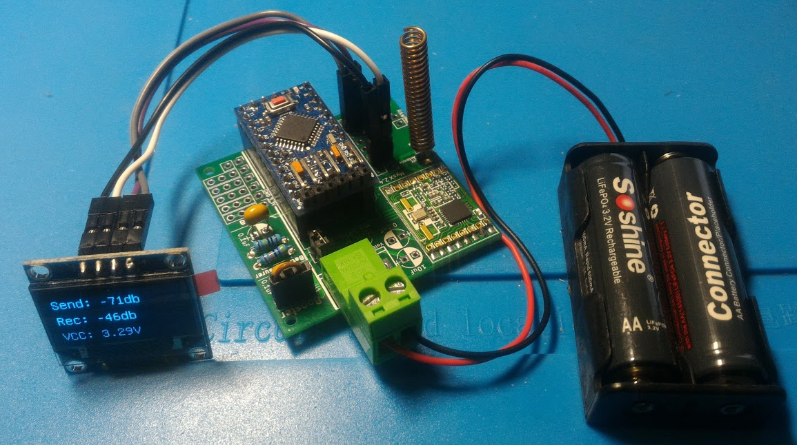
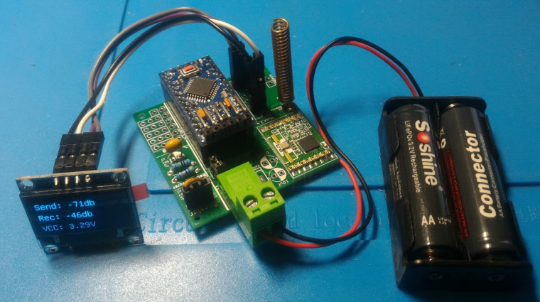
Portable RFM69 Signal Scanner
-
Nice job! Looks very dapper.
Alternatively, you may (?) be able to plug your screen directly into the I2C connector used for the TH sensor on:
https://www.openhardware.io/view/268/Arduino-Pro-Mini-Shield-for-RFM69HW
Depends on the pinout, of course. -
Here is the new code that uses the TX power readings. I think that RSSI values and tx power values could be useful to be reported by nodes every once and a while, at least to provide a feedback on how they are doing.
#include <U8glib.h> #include <Wire.h> //#define MY_DEBUG // Enable debug prints U8GLIB_SSD1306_128X64 lcd(U8G_I2C_OPT_DEV_0 | U8G_I2C_OPT_NO_ACK | U8G_I2C_OPT_FAST); // Fast I2C / TWI #define MY_RADIO_RFM69 #define MY_RFM69_FREQUENCY RFM69_433MHZ #define MY_RFM69_NEW_DRIVER #define MY_TRANSPORT_WAIT_READY_MS 10000 //#define MY_NODE_ID 240 //#define VBAT_VCC #include <SPI.h> #include <MySensors.h> #define CHILD_ID_VBAT 201 // Battery voltage unsigned long SLEEP_TIME = 2000; // Sleep time between reads (in milliseconds) #define SKETCH_NAME "Signal Monitor" // Change to a fancy name you like #define SKETCH_VERSION "1.0" // Your version MyMessage msgVBat(CHILD_ID_VBAT, V_VOLTAGE); int Send_rssi, Rec_rssi; // RSSI RFM69 chip #define CHILD_ID_RSSI_HIGH 7 // RSSI received signal level #define CHILD_ID_RSSI_LOW 8 // RSSI background noise level MyMessage msgRSSI1(CHILD_ID_RSSI_HIGH, V_LEVEL); MyMessage msgRSSI2(CHILD_ID_RSSI_LOW, V_LEVEL); //========================= // BATTERY VOLTAGE DIVIDER SETUP // 1M, 470K divider across battery and using internal ADC ref of 1.1V // Sense point is bypassed with 0.1 uF cap to reduce noise at that point // ((1e6+470e3)/470e3)*1.1 = Vmax = 3.44 Volts // 3.44/1023 = Volts per bit = 0.003363075 #define VBAT_PER_BITS 0.003363075 #define VMIN 2.8 // Vmin (radio Min Volt)=1.9V (564v) #define VMAX 3.44 // Vmax = (2xAA bat)=3.0V (892v) int batteryPcnt = 0; // Calc value for battery % int batLoop = 0; // Loop to help calc average int batArray[3]; // Array to store value for average calc. float Vbat; #ifdef VBAT_VCC #include <Vcc.h> const float VccCorrection = 1.0 / 1.0; // Measured Vcc by multimeter divided by reported Vcc Vcc vcc(VccCorrection); #else int BATTERY_SENSE_PIN = A0; // select the input pin for the battery sense point #endif // VBAT_VCC void setup() { analogReference(INTERNAL); // For battery sensing lcd.setFont(u8g_font_unifont); } void presentation() { // Send the Sketch Version Information to the Gateway sendSketchInfo(SKETCH_NAME, SKETCH_VERSION); // Register all sensors to gw (they will be created as child devices) present(CHILD_ID_RSSI_HIGH, S_SOUND); present(CHILD_ID_RSSI_LOW, S_SOUND); present(CHILD_ID_VBAT, S_MULTIMETER); } void loop() { delay(500); // Allow time for radio if power used as reset Send_rssi = RFM69_getSendingRSSI(); // read RSSI in RFM69. Measure reception signal from gw send(msgRSSI1.set(Send_rssi)); // send RSSI level wait(500); // wait to get idle Rec_rssi = RFM69_getReceivingRSSI(); // read RSSI in RFM69. Wait and measure background noise send(msgRSSI2.set(Rec_rssi)); // send RSSI level wait(200); // wait for next send batM(); lcd.firstPage(); do { UpdateDisplay(); } while (lcd.nextPage()); sleep(SLEEP_TIME); //sleep a bit } void UpdateDisplay() { lcd.setPrintPos(0, 20); String row; row = (String)"S/R: " + Send_rssi + "/"+ Rec_rssi +"db"; lcd.print(row); lcd.setPrintPos(0, 42); row = (String)"Pwr%: " + RFM69_getTxPowerPercent() + "%"; lcd.print(row); lcd.setPrintPos(0, 64); row = (String)"PWR: " + RFM69_getTxPowerLevel() + "db"; lcd.print(row); } void batM() //The battery calculations { delay(500); int batteryPcnt; // Battery monitoring reading #ifdef VBAT_VCC Vbat = vcc.Read_Volts(); batteryPcnt = vcc.Read_Perc(VMIN, VMAX); #else int sensorValue = analogRead(BATTERY_SENSE_PIN); Vbat = sensorValue * VBAT_PER_BITS; // Calculate the battery in % batteryPcnt = static_cast<int>(((Vbat - VMIN) / (VMAX - VMIN))*100.); #endif delay(500); send(msgVBat.set(Vbat, 2)); Serial.print("Battery percent: "); Serial.print(batteryPcnt); Serial.println(" %"); // Add it to array so we get an average of 3 (3x20min) batArray[batLoop] = batteryPcnt; if (batLoop > 2) { batteryPcnt = (batArray[0] + batArray[1] + batArray[2] + batArray[3]); batteryPcnt = batteryPcnt / 3; if (batteryPcnt > 100) { batteryPcnt = 100; } Serial.print("Battery Average (Send): "); Serial.print(batteryPcnt); Serial.println(" %"); sendBatteryLevel(batteryPcnt); batLoop = 0; } else { batLoop++; } } -
Nice clean signal scanner build! I must have one.
Is that an open source proto board you used? I couldn't find it poking around a bit.
Thanks for sharing it!
@grubstake I think it is an earlier revision of https://www.openhardware.io/view/389/EasyNewbie-PCB-RFM69-HWW-edition-for-MySensors
-
@grubstake I think it is an earlier revision of https://www.openhardware.io/view/389/EasyNewbie-PCB-RFM69-HWW-edition-for-MySensors
@mfalkvidd
Thanks, it looks like the Rev 9?, where the older pic you posted looks like a smaller version. I didn't realize the board was rearranged between Rev9 and recent R10.


