How to power 5V sensor?
-
Re: Easy/Newbie PCB for MySensors
Hi all,
Can somebody give me a tip on how to get 5V for the Distance Sensor on the Rev9 EasyPCB with 3.3V Arduino with battery power.
Use power booster?@peerv - well, if you have a 3.3v arduino - why power it with 5v? Do you have a sensor that req. this?
I would power everything with 5v from a USB adapter and use a voltage regulater on the PCB for 3.3vEdit... missed distance sensor.
-
Thanks, but..... need to power it with batteries!
What is the best approach to get 5V for the Distance Sensor?@peerv if you really really need to use that combination of 3.3v arduino and 5v sensor + battery, you'll probably need a step up booster. The problem with normal boosters is that they consume energy constantly so they may reduce the life of your battery. I'm not sure they exist but you may want to search for low quiescent current step up. If i remember well, pololu had some of those; some models include enable pins, so you could just switch the sensor off when not needed. I usually find the pololus on ebay.
-
Thanks, but..... need to power it with batteries!
What is the best approach to get 5V for the Distance Sensor?@peerv As @manutremo pointed out, these boosters use power, even when enable is switched down. The trick for battery power is to cut all but the basic standby power.
Having already gone through this evolution for a 5v ultrasonic, in my own case the solution was a 3v dual coil latching dpdt relay switched by two mosfets, requiring two pins to switch on and off. This offered switching of 5v power for the US on one contact, and 3v for the level converter on the other. The beauty of these small signal relays is the fast on/off times, and zero power consumption when latched in on/off.
I used separate battery packs for the node supply and the 5v circuit.... -
@peerv As @manutremo pointed out, these boosters use power, even when enable is switched down. The trick for battery power is to cut all but the basic standby power.
Having already gone through this evolution for a 5v ultrasonic, in my own case the solution was a 3v dual coil latching dpdt relay switched by two mosfets, requiring two pins to switch on and off. This offered switching of 5v power for the US on one contact, and 3v for the level converter on the other. The beauty of these small signal relays is the fast on/off times, and zero power consumption when latched in on/off.
I used separate battery packs for the node supply and the 5v circuit....@zboblamont - I have made some test with a 3.3v node and power to a 5v booster coming from a digital pin from the MCU. This pin can be turn off when not used, but I dont have any long term results... its truly a diy hack and there probably are 100 things that could go wrong with this setup.
A 5v sensor with a 3.3v node/battery is a hard one!
Controller: Proxmox VM - Home Assistant
MySensors GW: Arduino Uno - W5100 Ethernet, Gw Shield Nrf24l01+ 2,4Ghz
MySensors GW: Arduino Uno - Gw Shield RFM69, 433mhz
RFLink GW - Arduino Mega + RFLink Shield, 433mhz -
@zboblamont - I have made some test with a 3.3v node and power to a 5v booster coming from a digital pin from the MCU. This pin can be turn off when not used, but I dont have any long term results... its truly a diy hack and there probably are 100 things that could go wrong with this setup.
A 5v sensor with a 3.3v node/battery is a hard one!
@sundberg84 The only problem I found was a lack of available pins on the particular node type I selected due to onboard RTC and RFM69. I haven't decided yet whether to release additional pins by removing LEDs or switches.
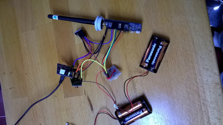
Top is the WhisperNode, below it the logic converter, left to right the ultrasonic, the booster and the relay board.
I had initially bought single coil latching relays, but this required an H bridge which posed issues. The dual coil relay solved the problem with mosfets driven from two pins.
Unfortunately I forgot that two pins I used for Trigger and Echo were needed by the RTC version, so not sure now whether to use the WhisperNode as a I2C receiver transmitter and have a 5v pro-mini cover the ultrasonic and the adjacent gas meter... -
@sundberg84 The only problem I found was a lack of available pins on the particular node type I selected due to onboard RTC and RFM69. I haven't decided yet whether to release additional pins by removing LEDs or switches.
Top is the WhisperNode, below it the logic converter, left to right the ultrasonic, the booster and the relay board.
I had initially bought single coil latching relays, but this required an H bridge which posed issues. The dual coil relay solved the problem with mosfets driven from two pins.
Unfortunately I forgot that two pins I used for Trigger and Echo were needed by the RTC version, so not sure now whether to use the WhisperNode as a I2C receiver transmitter and have a 5v pro-mini cover the ultrasonic and the adjacent gas meter...@zboblamont - I can see your strugle, and Im not sure if I would think its worth it. The amount of work and troubleshooting compared to building a 5v Pro mini? The only downside are that you need a powersupply (like a phonecharger) nearby.
-
@zboblamont - I can see your strugle, and Im not sure if I would think its worth it. The amount of work and troubleshooting compared to building a 5v Pro mini? The only downside are that you need a powersupply (like a phonecharger) nearby.
@sundberg84 The details and methods to release additional pins are all in the documentation, so not a problem, however my original idea was to have capability to swap over devices, hence my reluctance to do surgery.
Low energy use info is plentiful on the 5v pro-mini, the booster is the PIA for low energy, so that will probably be relay controlled in any instance...
A steep but interesting learning experience...
Hello! It looks like you're interested in this conversation, but you don't have an account yet.
Getting fed up of having to scroll through the same posts each visit? When you register for an account, you'll always come back to exactly where you were before, and choose to be notified of new replies (either via email, or push notification). You'll also be able to save bookmarks and upvote posts to show your appreciation to other community members.
With your input, this post could be even better 💗
Register Login