π¬ Multi-Sensor: Temp/Humidity/PIR/ Leak/Magnet/Light/Accel
-
@NeverDie said in CR2032 Small Wireless Temperature-Humidity Sensor:
Also, since the back of it is almost entirely ground plane anyway, it seems ripe for using a smaller profile CR2032 battery holder, such as: https://www.digikey.com/scripts/DkSearch/dksus.dll?Detail&itemSeq=243085164&uq=636456618668326452
Not only would it be thinner, but maybe (?) I could also shave a few millimeters off the PCB diameter .
So, yeah, I'm definitely open to improving the design.
Your link is broken, looks like a search result and not a product page
-
@Nca78 said in CR2032 Small Wireless Temperature-Humidity Sensor:
Your link is broken, looks like a search result and not a product page
Thanks for letting me know. Not sure what's going wrong. When I click on the link, it takes me right there.
Hmmmmm... The manufacturer's part number is "BK-913-TR". Try entering that into the search field on digikey. It's the one for $0.38.
-
I've just now uploaded Version 3, which fixes an overlap issue in Version 2 between the 10-pin connector and the optional Si7021/BME280. AFAIK, everything should work now.
-
@Nca78 said in CR2032 Small Wireless Temperature-Humidity Sensor:
Then there's the DRV5032 from TI that had the lowest power consumption a few month ago when I bought it, it's 0.5$ on Arrow and needs only 0.54uA in the FB (5Hz) version
https://www.arrow.com/en/products/drv5032fbdbzr/texas-instrumentsThanks for the links. I think I'll first try putting the Version 3 TH sensor into the deadbolt cavity and see what kind of range I get with that. It might be seriously impaired, since it will have metal on 2-3 sides. If I'm getting usable signal though at a decent range, then at that point I'll look into adding the DRV5032 to the board.
-
Yesterday I received an CR2477 button cell holder, and it appears that it can easily substitute for the CR2032 in the BOM: the pins seem very much aligned.
https://www.digikey.com/product-detail/en/mpd-memory-protection-devices/BH1000G/BH1000G-ND/140383
Therefore, if you want a battery with roughly 4x the mah and which can also support a higher current drain than a CR2032, it's a good option.
-
@Nca78 said in CR2032 Small Wireless Temperature-Humidity Sensor:
Your link is broken, looks like a search result and not a product page
-
I just now uploaded some demo source code that will make the node into a proper MySensors temperature node.
-
I just now uploaded the Version 4 files. The new design uses the more compact CR2032 battery holder discussed above.
-
@Nca78 said in CR2032 Small Wireless Temperature-Humidity Sensor:
Also, what about moving the led to the center next to its resistor, it would leave enough space to squeeze in a SOT 23 ultra low power hall sensor and it's 100nF capacitor.
Yes, with the Version 4 design serving as the basis, I think there will be enough room to do this.
I'd also like to add a light sensor of some kind: something that will trigger an interrupt when, say, a refrigerator light goes on or off (for the case where the temperature node is in a refrigertor or freezer). Do you have any particular suggestions for that? A simple photoresistor, or would there be something better (lower current)?
-
Low current light sensor with interrupt, you have OPT3001 and MAX44009. MAX44009 has the lowest power but it doesn't have the same availability (not on Arrows for example).
If you're planning to use it from breakout board (as they are boath really tiny) then MAX44009 is the best choice as it's cheaper on AliExpress.If you want one that you can solder by hand you can check VEML7700, it's cheap, has low power consumption (2uA) if you use a low refresh rate. But it goes only down to 2.5V so you will lose a bit of the capacity of the button cell, and it has no interrupt pin.
-
@Nca78 said in CR2032 Small Wireless Temperature-Humidity Sensor:
Also, what about moving the led to the center next to its resistor, it would leave enough space to squeeze in a SOT 23 ultra low power hall sensor and it's 100nF capacitor.
Done. I just now uploaded Version 5, which has the TI hall effect sensor.
-
@Nca78 said in CR2032 Small Wireless Temperature-Humidity Sensor:
MAX44009 has the lowest power but it doesn't have the same availability (not on Arrows for example).
If you're planning to use it from breakout board (as they are boath really tiny) then MAX44009 is the best choice as it's cheaper on AliExpress.Looks as though if I add just one more header pin, then I can use this board:
https://www.aliexpress.com/item/MAX44009-Ambient-Light-Sensor-Module-with-4P-Pin-Header-Module/32729312303.html?spm=2114.search0204.3.47.XOZuu8&ws_ab_test=searchweb0_0,searchweb201602_4_10152_10065_10151_10344_10068_10130_10345_10324_10342_10547_10325_10343_10546_10340_10341_10548_10545_10541_10562_10084_10083_10307_10178_10060_10155_5680017_10154_10056_10055_10539_10537_10312_10536_10059_10313_10314_10534_10533_100031_10103_10073_10102_10557_10558_10142_10107-10178,searchweb201603_25,ppcSwitch_4_ppcChannel&btsid=ca20f561-ad43-4536-b09f-7856bf41fbb2&algo_expid=0601cfd8-6d07-4336-aefc-c06bc54166ac-2&algo_pvid=0601cfd8-6d07-4336-aefc-c06bc54166ac
That way I could capture the interrupt.
-
OK, I just now uploaded the files for Version 6, which does just that. Unless someone can think of another sensor to add, I think this will be the final version (unless errors are discovered).
-
I'm quite a noob, but totally with the NRF. Interesting PCB, I'll try asap to put a sensor together!
-
I made one last change to add water leak detection to it. I just now uploaded the version 7 files.
-
I have the Version 1 design now working with the si7021 breakout board that I got from Aliexpress. Note that if you use these breakout boards, remember to remove the voltage regulator and solder bridge across the two pins as shown in the photo below:
This is because the coin-cell voltage is already in the desired range, and so there's no need for further voltage reduction.
-
Is v7 already for CR2477? BOM still mentions CR2032
-
@Toyman said in Small Wireless Temp/Humidity Leak/Magnet/Light/Accel Sensor:
Is v7 already for CR2477? BOM still mentions CR2032
If I had kept the same button cell holder as some of the earlier version it would be. However, I switched to a narrower profile battery holder in the BOM (which benefits the leakage sensor part of the design). Not sure if an equivalent CR2477 holder is still available with the new design. Haven't checked. When I brought up the possibility of a CR2477 earlier, it didn't seem to generate much enthusiasm at the time. So, I took that to mean most people weren't really interested.
-
Nice project!
What about adding two resistors to measure and send the battery level as well?
-
@krisha said in Small Wireless Temp/Humidity Leak/Magnet/Light/Accel Sensor:
What about adding two resistors to measure and send the battery level as well?
not needed. You can measure the battery voltage without a divider.
-
I just now uploaded the Version 8 files, which contains pads for an optional 100uF ceramic capacitor. Thank you to @nca78 and @scalz for the suggestion.
-
Now reads temperature and humidity from the si7021 and sends the values to Domoticz for graphing:
-
...another n00b question: what are the PCB dimensions?
-
@ghiglie said in Multi-Sensor: Temp/Humidity Leak/Magnet/Light/Accel:
...another n00b question: what are the PCB dimensions?
The diameter is 27.15mm.
-
@NeverDie Thanks! I'll ask the fab if they can do it without charging extra costs. Or I'll "square" it - maybe with a hole in the angles to screw it. Really like this design.
-
@ghiglie What is it that you'd want to screw it to? It might be easier to just tape it or glue it in place. It's light enough that it wouldn't need much holding strength. Screwing may be overkill.
-
@NeverDie said in Multi-Sensor: Temp/Humidity Leak/Magnet/Light/Accel:
@ghiglie What is it that you'd want to screw it to? It might be easier to just tape it or glue it in place. It's light enough that it wouldn't need much holding strength. Screwing may be overkill.
I was thinking about the top of a door... You'r right, I overestimated its weight.
-
@ghiglie said in Multi-Sensor: Temp/Humidity Leak/Magnet/Light/Accel:
@NeverDie said in Multi-Sensor: Temp/Humidity Leak/Magnet/Light/Accel:
@ghiglie What is it that you'd want to screw it to? It might be easier to just tape it or glue it in place. It's light enough that it wouldn't need much holding strength. Screwing may be overkill.
I was thinking about the top of a door... You'r right, I overestimated its weight.
If you've never tried them, these things are great:
https://www.amazon.com/Command-Poster-Hanging-60-Pairs-17024-60ES/dp/B01FIK56Q4/ref=sr_1_3?ie=UTF8&qid=1510769859&sr=8-3&keywords=3m%2Bcommand%2Bmounting&th=1
They have a lot of holding power (more than ample for one of these sensors), and yet they can be cleanly removed without damaging the surface you hang it on.3M also has a velcro-like version so that you can attach, then detach and re-attach as much as you want.
-
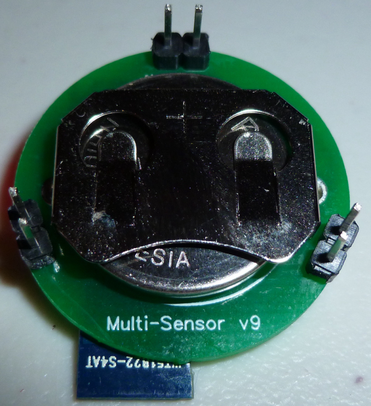
First, the good news: it works! I've uploaded photos of the version 7 board that I just today received and put together. It powered up without a hitch and started sending temperature and humidity values to Domoticz like a champ. The one caveat is that I will need to increase the board diameter by a couple of millimeters, as there presently just isn't enough proper physical separation between the supportive male leak detection pins and the CR2032 battery holder. So, I will do that, and I will post a version 9 after I have received and tested the improved boards.
-
@NeverDie Thanks! Here in Italy they's sold with another name, but it's still a 3M branded one. I'll look for a pack!
-
I have uploaded version 9. This should fix the physical clearance issue. Also, I upgraded the cap to be a 1206 220uF ceramic capacitor, as the cost is nearly the same as for an 0805 100uF capacitor. I should think that 220uF will offer plenty of reserve for the future when the battery ultimately develops a high internal resistance.
-
More good news: I today received the PCB for a revision of my PIR module that's meant to be compatible with this Multi-Sensor. I just now did a dry-fitting, and, indeed, it should all fit together just fine:
That means the entire PIR sensor can be quite small and compact!
-
For PIR capability, the multi-sensor can simply plug into this PIR module: https://www.openhardware.io/view/420/AM612-Passive-Infrared-Sensor-Breakout-Board
-
I have an experimental version in the works which uses a micro USB connector instead of the 10-pin connector. The advantage is that it can be connected from the side rather than above, which means the PIR sensor can be snuggled up close to the rest of the Multi-Sensor PCB and then permanently soldered into place:
The result would be an even more compact PIR sensor.Once there's an OTA bootloader, though, this issue will become moot, and so I think for most people the 10-pin solution will be easier, especially for noobs.
-
@nca78 Which do you think would be the best accelerometer to use? If affixed to a garbage can, for instance, it should be able to detect the trash can being emptied by the garbage truck.
-
@NeverDie said in Multi-Sensor: Temp/Humidity/PIR/ Leak/Magnet/Light/Accel:
@nca78 Which do you think would be the best accelerometer to use? If affixed to a garbage can, for instance, it should be able to detect the trash can being emptied by the garbage truck.
That's a very tough question
For low power the best is ADXL362 but it can only be controlled using SPI which is a problem for that specific NRF51 module. And it's not that convenient as low power comes with limited "advanced" capabilities that would be useful for this kind of sensor: tap/double tap detection, free fall detection, ...I'm making a board with the same nrf51 module and my choice is LIS3DE because it has those advanced functions and can go as low as 2uA, it's very cheap (<1$) and it's small, but I'm only using the chip and not a breakout board. There are LIS3DH breakout boards on AliExpress, it's similar but the boards are big as they map all pins in a row. Only board with less pin is nearly as expensive as some NRF51 + LIS3DE combo so it's not worth buying the breakout.
I will make a version with a LSM303AGR too, it has accelerometer + magnetometer. Magnetometer is power hungry but you can use it only when accelerometer detects some movement, so you know the orientation of the sensor. That way you could easily know the difference between your garbage can being moved around, and it being turned over in the garbage truck. But here again bad news in term of breakout boards, the LSM303 breakout boards available are not the -AGR version, and I'm not sure they can run the accelerometer in a real low power way (LSM303AGR is 3.7uA in lowest power accelerator mode).
There are also some Bosh accelerometer but using more current (6.5uA for BMA255 for example) and same problems with the breakout boards: they are huge.
Sorry, no good answer to your question as there's no compact, low power, i2c compatible breakout board that I know about. If you want to use a breakout board my advice is to go for ADXL362, and if you're out of pins with this nrf51 module you can hardwire the chip select pin to save one.
-
@NeverDie you can also measure tilt using an accelerometer (acceleration measured is the gravity in that case) but it's possible only if there is no movement, so I don't think it's usable in a garbage truck processing.
-
I guess it's the land of compromise. By default I'm going with the BMA220, if only because the board is small and the low power mode current drain is 10ua: https://www.aliexpress.com/store/product/DFRobot-BMA220-3-Axis-Triple-Axis-Accelerometer-sensor-2-0-3-6V-I2C-Interface-Tiny-size/1681007_32791058717.html
It's not cheap, but I only need a couple: one for trash can and the other for a curbside recycling bin.You're right though: maybe all I need is some kind of tilt detector, like maybe a mercury switch of some kind. Perhaps that would be cheaper, and the current drain could be almost nothing.... Thanks!
-
@NeverDie said in Multi-Sensor: Temp/Humidity/PIR/ Leak/Magnet/Light/Accel:
I guess it's the land of compromise. By default I'm going with the BMA220, if only because the board is small and the low power mode current drain is 10ua
At this price buy the small LIS3DH breakout, you'll enjoy the included tilt calculation and a 2uA consumption, 10uA for button cell it too high
https://www.aliexpress.com/item/LIS3DH-Module-Acceleration-Sensor-Module-Evaluation-Board-Development-Board/32285377730.htmlElse go for that one it's cheaper and has the nrf51822 onboard
https://www.aliexpress.com/item/Nrf51822-LIS3DH-Bluetooth-Module-CJMCU-8223-Bluetooth-acceleration-module/32821873481.html
-
@Nca78 said in Multi-Sensor: Temp/Humidity/PIR/ Leak/Magnet/Light/Accel:
Those are both good suggestions. Thinking now though of minimal effort, I may try some cheap ball sensors first:
https://www.aliexpress.com/item/200PCS-LOT-Sensitive-SW-520D-Ball-Switch-Angle-Switch-SW-520D-Tilt-Switch/1967714977.html?ws_ab_test=searchweb0_0,searchweb201602_4_10152_10065_10151_10344_10068_10130_10345_10324_10342_10547_10325_10343_10546_10340_10341_10548_10545_10541_10562_10084_10083_10307_10178_10060_10155_10154_10539_10312_10059_10313_10314_10534_10533_100031_10103_10073_10594_10557_10558_10596_10595_10142_10107,searchweb201603_25,ppcSwitch_4&btsid=110cafb1-1528-4ca9-bf01-4df9ccf33b93&algo_expid=8506dd81-1d5d-4627-9ae5-f3df06594fbb-9&algo_pvid=8506dd81-1d5d-4627-9ae5-f3df06594fbb&rmStoreLevelAB=0
I could stick it in one of the leak detection pinouts of my existing board, so it should be easy.
-
Actually, this contraption looks even more promising than the ball switch: https://www.aliexpress.com/item/Vibration-Switch-Shock-Vibration-Sensor-Shaked-Switch-Shaked-Stick-Skates/32686838884.html?ws_ab_test=searchweb0_0,searchweb201602_4_10152_10065_10151_10344_10068_10130_10345_10324_10342_10547_10325_10343_10546_10340_10341_10548_10545_10541_10562_10084_10083_10307_10178_10060_10155_10154_10539_10312_10059_10313_10314_10534_10533_100031_10103_10073_10594_10557_10558_10596_10595_10142_10107,searchweb201603_25,ppcSwitch_4&btsid=8ee4bf46-c3de-4f6a-b23f-32b800aefc7a&algo_expid=d469a8ff-4dce-4442-8590-0e2fdefb1f4b-14&algo_pvid=d469a8ff-4dce-4442-8590-0e2fdefb1f4b&rmStoreLevelAB=0
-
I uploaded new, upgraded demo code. It's tested and works.
SUMMARY: The demo sketch runs on MultiSensor Version 7 board with an I2C Si7021 module to transmit temperature, humidity, and battery voltage to a MySensors gateway using MySensors protocols.
-
@NeverDie have you seen the comments ?
Damn thing works only for the impact of accelerations> 50g. and only in one direction. In life it is not applicable. Shit, shorter.
-
@Nca78 No, I hadn't. Now I'm wishing I had. Good catch! I'll try cancelling my order....
-
Thinking about it more now, I think the ball switch will definitely work if I position it with a vertical orientation, because they invariably fully invert the trash/recycling bin in order to empty it.
-
Here's a node with the Hall sensor installed:
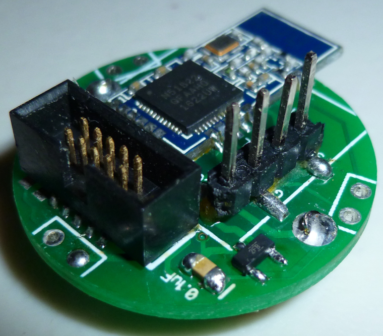
I'll probably be testing it later today.
-
Tested. The Hall sensor works. Basically, if you run this code:
#define HALL_PIN 9 hwPinMode(HALL_PIN, INPUT); while (true) { if (digitalRead(HALL_PIN)) { digitalWrite(LED_BUILTIN,LOW); } else { digitalWrite(LED_BUILTIN,HIGH); } }
then the LED will turn-on when you bring a magnet near the sensor, and the LED will turn-off when you move the magnet away. Simple.
-
Great!
A bit OT: how are you programming the nRF?
-
@ghiglie I plug it into the nRF52 DK using an IDC cable to its 10-pin connector. Then just select J-Link as the programmer and upload my sketch over the USB port connection to the nRF52 DK from within the Arduino IDE. Easy!
-
@NeverDie
Did you or anybody else could write to the NRF5xxx via the Arduino IDE and a ST-Link V2 programmer?
I find the DK for approx. 32β¬ a little bit to expensive for just testing.Edit: Maybe this one could work:
http://s.aliexpress.com/FRzU3miMThanks.
-
@DerManni said in Multi-Sensor: Temp/Humidity/PIR/ Leak/Magnet/Light/Accel:
ST-Link V2 programmer
Not me. As I said, I'm using the nRF52 DK as my programmer of choice. I think others may be using the ST-Link V2. Not 100% sure though.
-
@NeverDie
Yes i am using the STLink v2 without any problems.
-
@rmtucker Could you please explain in weich was you connect the STLINK to the NRF Module to usw the Arduino IDE. Thanks
-
STLink<----------------->NRF
SWCLK<--------------->SWD
SWDIO<---------------->SWIO
3.3v<--------------------->3.3v
GND<-------------------->GND
-
I received the version 9 PCB's today. Here's one assembled as a minimalist water leak sensor:
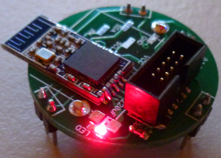
There's now enough physical clearance between the male header leak detection pins and the CR2032 battery holder that I feel comfortable declaring the hardware as finished.
-
@NeverDie said in Multi-Sensor: Temp/Humidity/PIR/ Leak/Magnet/Light/Accel:
@Nca78 said in CR2032 Small Wireless Temperature-Humidity Sensor:
Also, what about moving the led to the center next to its resistor, it would leave enough space to squeeze in a SOT 23 ultra low power hall sensor and it's 100nF capacitor.
Yes, with the Version 4 design serving as the basis, I think there will be enough room to do this.
I'd also like to add a light sensor of some kind: something that will trigger an interrupt when, say, a refrigerator light goes on or off (for the case where the temperature node is in a refrigertor or freezer). Do you have any particular suggestions for that? A simple photoresistor, or would there be something better (lower current)?
A photoresistor turns out to work just fine for binary detection of whether a light is on or off:
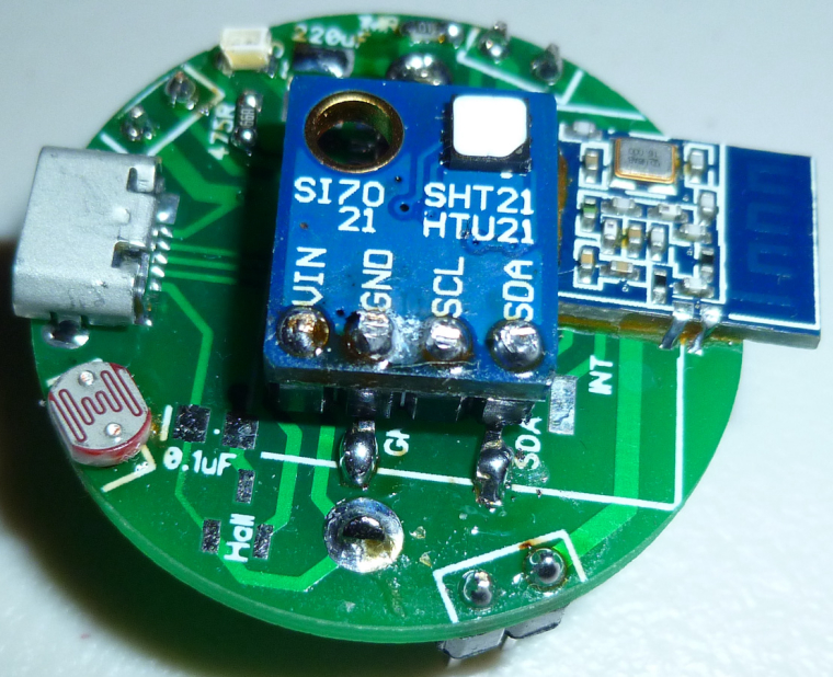
I put it in one of the header pin hole pairs otherwise reserved for the leak detection pins and then ran the leak detection sketch. When a light goes on, the resistance of the photoresistor goes from about 20 megaohms in the dark down to well under 100K ohms (exactly amount depends on the light intensity) in the light. So, under light stimulus the photoresistor behaves essentially the same as leak detection pins which have come into contact with water.The one I used is this: https://www.digikey.com/product-detail/en/luna-optoelectronics/NSL-19M51/NSL-19M51-ND/5039794 Perhaps a cheaper photoresistor would have worked just as well, but for proof of concept prototyping I wanted to try this one, which had desirable specs.
-
@NeverDie It appears that photoresistors of type 5539 and/or 5549 may work as well: https://www.aliexpress.com/item/Free-shipping-20pcs-5549-light-dependent-resistor-photoresistor-resistor-5mm-photosensitive-resistance-35513/32346773727.html?ws_ab_test=searchweb0_0,searchweb201602_4_10152_10065_5000015_10151_10344_10068_10130_10345_10324_10342_10547_10325_10343_10546_10340_10341_10548_10545_5130015_10541_10084_10083_10307_5690015_10539_5080015_10312_10059_10313_10314_10534_100031_10604_10603_10103_10605_5060015_10596_10142_10107,searchweb201603_12,ppcSwitch_4&algo_expid=14488cca-cb1a-4d45-b8d2-d8b444735f2a-16&algo_pvid=14488cca-cb1a-4d45-b8d2-d8b444735f2a&rmStoreLevelAB=2
-
@NeverDie and what is your approximative power consumption with the photoresistor ?
-
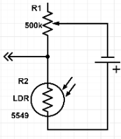
@NeverDie When using a voltage-divider setup with the LDR you'll have better control over the tripping point and consume less standby power:
Make sure to select an LDR with high resistance, like the 5549 in my example.
-
@Nca78 said in Multi-Sensor: Temp/Humidity/PIR/ Leak/Magnet/Light/Accel:
@NeverDie and what is your approximative power consumption with the photoresistor ?
With the photoresistor installed, current consumption for the entire node measures out at 4ua in the dark and 7.2ua in full saturation brightness. That compares to 3.9ua current consumption for the node with no photoresistor installed.
I'm still waiting for the I2C light sensor to arrive. However, as these photoresistors cost only a little more than 2 cents each for a pack of 50 (see above Aliexpress link), I think they're a reasonable choice for a refrigerator app, where it's going to be completely dark most of the time anyway.
-
@NeverDie said in Multi-Sensor: Temp/Humidity/PIR/ Leak/Magnet/Light/Accel:
I'm still waiting for the I2C light sensor to arrive. However, as these photoresistors cost only a little more than 2 cents each for a pack of 50 (see above Aliexpress link), I think they're a reasonable choice for a refrigerator app, where it's going to be completely dark most of the time anyway.
Yes it's nearly not changing the consumption in sleep so if you have only a basic use for dark/light it's a waste to use an i2c sensor, which will use more energy most of the time.
-
@nca78 What would be a good tiny buzzer to put on it, for making one of those ever popular location tags? I'm guessing something piezo? I'm not finding anything tiny though.
-
-
@neverdie this looks pretty small for a buzzer already. Sorry no idea about smaller ones, but please post your results I'm interested
-
@nca78 Will do. I ordered 20 of them. Might be a nice addition on a leak detector also.
-
I finally received the MAX44009 board:
https://www.aliexpress.com/item/Smart-Electronics-5PCS-lot-MAX44009-ambient-light-sensor-is-the-I2C-digital-output-module-development-board/32767691971.html?spm=a2g0s.9042311.0.0.sOFetX
I'm able to read lux values by pulling A0 on the board to Vcc and using this library and sketch:
https://github.com/dantudose/MAX44009/blob/master/Example/Luxmeter.ino
Very easy.
-
@neverdie you don't even need to bother with a lib, just 2 functions are enough.
https://blog.kkessler.com/tag/max44009/
-
even if it's two functions only, if i need to reuse them in others sketch, I would prefer them in a lib. Only "one line" (include) in the sketch compared to x lines
-
@nca78 said in Multi-Sensor: Temp/Humidity/PIR/ Leak/Magnet/Light/Accel:
@neverdie this looks pretty small for a buzzer already. Sorry no idea about smaller ones, but please post your results I'm interested
Received it today. Putting just DC across it produces no sound at all. Driving it with a pulsed voltage (say 10K hertz at 50% duty cycle) directly from an arduino pin produces sound, but at very low volume. Since it draws 220ma with a straight 3v DC voltage across it, I'm guessing a current more like that is what it will take to get it to produce louder sound, but that's only just a wild guess.
-
I tried driving it from a load switch controlled by the arduino, and that helped increase the volume somewhat.
Doing that, and using this script, I think it will be audible if you're in the same room as it (and if the room is otherwise quiet).
long lastMicrosTime=0; //timestamp in microseconds void setup() { pinMode(10,OUTPUT); } void loop() { for (int x=0;x<1000;x++) { digitalWrite(10,HIGH); lastMicrosTime=micros(); while ((micros()-lastMicrosTime)<300) {} //wait until 300 microseconds have passed digitalWrite(10,LOW); while ((micros()-lastMicrosTime)<x) {} //wait until another x microseconds have passed } }
So, if you were to use it as a locator beacon attached to something you wanted to find, it might be good enough for that.
-
@neverdie said in Multi-Sensor: Temp/Humidity/PIR/ Leak/Magnet/Light/Accel:
Doing that, and using this script, I think it will be audible if you're in the same room as it (and if the room is otherwise quiet).
Guess this is not made for Vietnam then
I supposed this type of buzzer is made more for user feedback for things like touch sensors, than for raising alert.
-
@nca78 What strange is that if I cup my hand over it, it actually becomes louder. Not sure what's up with that. So, maybe I'm just not driving it right.
-
Here's the latest version of the PIR sensor embodiment:
It runs from two CR2032's.Very compact!
-
@neverdie how do you connect thr two Cr batteries ?
Another question ? I read in another comments that you need 100-200 uF capacitor so that the radio can work since thr CR battery wont be strong enough. Did you add this ?
-
@ahmedadelhosni said in Multi-Sensor: Temp/Humidity/PIR/ Leak/Magnet/Light/Accel:
how do you connect thr two Cr batteries ?
This was recently discussed in the Bluetooth action! thread.
-
@neverdie said in Multi-Sensor: Temp/Humidity/PIR/ Leak/Magnet/Light/Accel:
@nca78 What strange is that if I cup my hand over it, it actually becomes louder. Not sure what's up with that. So, maybe I'm just not driving it right.
Isn't that the principle for most speakers, using a sound box ?
-
Wich board do you use in arduino? I can only use Waveshare BLE4.0. At Generic etc. It seems, that the oscillator doesn't work probably.
-
@tiwo85 said in Multi-Sensor: Temp/Humidity/PIR/ Leak/Magnet/Light/Accel:
Wich board do you use in arduino? I
Not sure what you're asking.
-
@neverdie I mean this:
When I use Generic nRF51 or something else, the onboard LED turns on and doesn't turns off. When I use Waveshare BLE400 the sketch works as usual
-
-
@neverdie do you have a working example sketch. I try the example sketch from the 10years pir sensor an d modify a little bit, but it doesn't work. The sketch awake every 5 minutes and send the state from the pir and that's it.
-
@tiwo85
https://www.openhardware.io/view/510/Multi-Sensor-TempHumidityPIR-LeakMagnetLightAccel#tabs-source
-
@neverdie thank you. I made this sketch work. But I need to get work interrupts. I use your code for the am612, but it doesn't work. Then I use the example from Redbear labs "Example interrupted" to turn on the led when p0.02 is high. I use Mysensors library and set My Core only. Then it runs. But when I try to integrate Mysensors routines "presentation" etc. And disable "my core only" , then the interrupt doesn't work.
// SUMMARY: This demo sketch runs on the AM612 PIR v607 PCBto transmit battery voltage (heartbeat) and motion detections to a MySensors gateway using MySensors protocols. // Note: because this is a passive node, node ID must be set manually to a unique sensor node ID: #define MY_NODE_ID 143 // Passive mode requires static node ID //#define MY_CORE_ONLY #define MY_PASSIVE_NODE #define MY_RADIO_NRF5_ESB /** * The MySensors Arduino library handles the wireless radio link and protocol * between your home built sensors/actuators and HA controller of choice. * The sensors forms a self healing radio network with optional repeaters. Each * repeater and gateway builds a routing tables in EEPROM which keeps track of the * network topology allowing messages to be routed to nodes. * * Created by Henrik Ekblad <henrik.ekblad@mysensors.org> * Copyright (C) 2013-2017 Sensnology AB * Full contributor list: https://github.com/mysensors/Arduino/graphs/contributors * * Documentation: http://www.mysensors.org * Support Forum: http://forum.mysensors.org * * This program is free software; you can redistribute it and/or * modify it under the terms of the GNU General Public License * version 2 as published by the Free Software Foundation. * ******************************* * * REVISION HISTORY * Version 1.0 - tekka * * DESCRIPTION * Passive node example: This is a passive & independent reporting node * */ // This demo sketch also draws from the MySensor's example MotionSensor sketch. #define IS_NRF51 //true iff the target is an nRF51. If an nRF52, then comment this line out! #define SHORT_WAIT 50 // Enable debug prints //#define MY_DEBUG #define PIN_LED1 (4) // 4 is sensor LED , 1 is onboard LED #define LED_BUILTIN PIN_LED1 #define PIN_SENSOR1 (10) // 2 is waterleak, 10 is PIR , 3 is Pin5/INT #define SENSOR1 PIN_SENSOR1 #include <MySensors.h> //#define CHILD_ID_TEMP 1 //definitions contributed by smilvert (see above credit) #define CHILD_ID 2 // Id of the motion sensor child #define ID_S_MULTIMETER 28 // Initialize general message //MyMessage msgTemp(CHILD_ID_TEMP, V_TEMP); MyMessage msg(CHILD_ID, V_TRIPPED); MyMessage msg_S_MULTIMETER_V_VOLTAGE(ID_S_MULTIMETER,V_VOLTAGE); float batteryVoltage=0; /*#include "nrf_temp.h" float read_temp_value(){ float temp=0; // Starten Sie die Temperaturmessung. NRF_TEMP->TASKS_START = 1; // Warten Sie, bis die Temperaturmessung abgeschlossen ist. while (NRF_TEMP->EVENTS_DATARDY == 0){ // Do nothing.} } NRF_TEMP->EVENTS_DATARDY = 0; // Lesen Sie den Temperaturwert vom Sensor ab // Die Genauigkeit betrΓ€gt 0,25 Grad Celsius <=> 1 Einheit = 0,25 Grad Celsius // Teile durch 4, um einen C-Wert zu erhalten temp = ((float)nrf_temp_read() / 4.); // HoΓ n thΓ nh quΓ‘ trΓ¬nh Δo. NRF_TEMP->TASKS_STOP = 1; return temp; }*/ void blinkityBlink(uint8_t repetitions) { for (int x=0;x<repetitions;x++) { digitalWrite(LED_BUILTIN ,HIGH); delay(20); digitalWrite(LED_BUILTIN ,LOW); delay(100); digitalWrite(LED_BUILTIN ,HIGH); delay(20); digitalWrite(LED_BUILTIN ,LOW); if (x<(repetitions-1)) { //skip waiting at the end of the final repetition delay(500); } } } void handle_irq3(void) { if(HIGH == digitalRead(SENSOR1)){ digitalWrite(LED_BUILTIN , HIGH); send(msg.set("1")); // motion detected } else { digitalWrite(LED_BUILTIN , LOW); send(msg.set("0")); // send all-clear to prepare for future detections } } void presentation() { // Send the sketch version information to the gateway and Controller sendSketchInfo("NRF Motion Sensor", "1.0"); // wait(SHORT_WAIT); // present(CHILD_ID_TEMP, S_TEMP,"Onboard Temperature"); wait(SHORT_WAIT); // Register all sensors to gw (they will be created as child devices) present(CHILD_ID, S_MOTION,"Motion Sensor"); wait(SHORT_WAIT); present(ID_S_MULTIMETER,S_MULTIMETER,"Electric Station"); wait(SHORT_WAIT); } void setup() { // put your setup code here, to run once: //hwInit(); //hwPinMode(LED_BUILTIN,OUTPUT_D0H1); //hwPinMode(SENSOR1,INPUT); //nrf_temp_init(); pinMode(LED_BUILTIN , OUTPUT); digitalWrite(LED_BUILTIN , LOW); blinkityBlink(5); //signify power-up and start of operations // set interrupts, pin default is HIGH attachInterrupt(SENSOR1, handle_irq3, CHANGE); } void loop() { // put your main code here, to run repeatedly: //send(msgTemp.set(read_temp_value(),2)); batteryVoltage=((float)hwCPUVoltage())/1000.0; //take voltage measurement after transmission to hopefully measure lowest voltage that occurs. send(msg_S_MULTIMETER_V_VOLTAGE.set(batteryVoltage,3)); //send battery voltage with 3 decimal places sleep(900000); //sleep 15 min }
-
@tiwo85 I suggest you start a different thread on your interrupt problems, since that's really a separate issue and not specific to this hardware.
-
Hi,
I like to buy this board and your AM612 breakout pcb through hardware.io.
But first I have few questions unfortunately I couldn't find the answers here in this thread/forum.
-
I assume this board has to be programmed via the 10pin box header. How can I connect it to my computer? I think there is some adapter or similar required? Any selfmade options available? In this thread I saw that it should be possible to program this device via the Arduino IDE?
-
Can I mount the following sensors at the same time without space conflicts:
- Motion PIR (AM612breakout)
- Temp + Humidity
- Light
-
Does this board have some free digital pins for door contact and or relais? (if yes, how many?)
-
(Optional) I think there are no MISO/MOSI/... pins for connecting a RFM69 module?
I don't like to use the battery option. I will power the board via power supply. Can I connect a 5V power supply to the battery pins or what is the best option?
Thanks in advance.
-
-
Hello @ehome
-
it is based on an arduino pro mini (NModule board, don't forget that this is just a shield for NModule) , so you program the arduino pro-mini, usually using an FTDI adapter. You should find plenty of explanations online.
For programming bootloader/fuses, you can use and arduino nano with the ArduinoISP sketch: MOSI=>MOSI, MISO=>MISO, SCK=>SCK and SS (pin 10) of nano to reset pin of the pro mini. Here also you will find plenty of examples/videos etc online.
Start with reading the page about NModule:
https://www.openhardware.io/view/364/NModule -
In theory yes if light sensor is on the AM612 breakout. I will test this configuration next week and confirm to you that it is working before you order the board. If you don't hear any news about that before the end of next week ring me a bell here as it probably means I forgot
-
You will use one of the external interrupt pins (pin 3) for the PIR sensor, so you will have one left (pin 2). If you don't use the leds there are 3 other input pins available on the NModule connector (A1,A2,A3, you can use them as digital inputs too), on battery powered sensors it needs pin change interrupts, but as you are using a power supply it won't be a problem.
-
No you can't connect a RFM module, NModule is only for SMD NRF24 modules
-
You should connect power to RAW and GND pins on the NModule connector. The best is to use AMS1117 regulator to get the 3.3V, it's probably overkill for your usage but it's very stable and will filter the noise of your power supply much better than the XC6206 (which more suitable for a li-ion powered node). In addition you will be able to use a power supply up to 12V
-
-
@Nca78 many thanks for your answer. Maybe may question was a little bit too vague. I didn't mean the NMODULE board. I was speaking about the NRF51xxx board from @NeverDie
-
@ehome said in Multi-Sensor: Temp/Humidity/PIR/ Leak/Magnet/Light/Accel:
@Nca78 many thanks for your answer. Maybe may question was a little bit too vague. I didn't mean the NMODULE board. I was speaking about the NRF51xxx board from @NeverDie
These are shield made to work with the NModule. For the same sensors I think @NeverDie has what you need in NRF5 versions, so ask him on the right thread
-
Hi all, i try NRF51822-04 module with this sketch and Si7021 as GY-21 sensor, communication over radio works great, but i still got Humidity 118% and Temperature 128Β°C
can anyone help me?
Si7021 is connected to P0.10 - SCL and P0.4 - SDA
-
-
I've downloaded the source files and tried to compile them.
I got fatal error: sketch/MyBoardNRF5.h: No such file or directory -
Then I renamed MyNRF5Board.h to MyBoardNRF5.h
I got #error No forward link or gateway feature activated. This means nowhere to send messages! Pretty pointless. -
Then I added #define MY_GATEWAY_SERIAL into the code
I got many errors i.e. 'PIN_AIN0' was not declared in this scope
How to compile the downloaded source files?
-
-
Hi,
What is the power consumption you get with this board and i2c sensors? I built several boards and measured the consumption using a INA219 sensor (lowest resolution is 0.1mA). Without any I2C sensor initialized, it shows a power consumption well below 0.1mA (i.e. it always shows 0.0), but as soon as I use an I2C sensor, the consumption during sleep increases to 0.3mA, which drains the battery faster than desired for a battery node...I tried it with several different implementations / sensors, and always got the same result:
- MyBoardNRF5 with BME280 (Adafruit library), sketch adapted from the one supplied with this board
- MyBoardNRF5 with BME280 using NodeManger
- MyBoardNRF5 with VL53L0x using NodeManager
- Custom board in Arduino IDE derived from Sandeep Mistry's generic 51822 board, with either of the above sketches
Is there anything special I need to do to get power consumption with i2c sensors down to the desired single-digit-Β΅A-range during sleep?
-
@reinhold I'm not sure if this helps, but I had 450uA drain when sleeping and shut down I2C everytime I'm done reading:
void i2c_off() // Shut i2c down, power consumption rises up to 450uA instead of 11 ua - https://github.com/sandeepmistry/arduino-nRF5/issues/291#issuecomment-407492282 { NRF_TWI1->ENABLE=TWI_ENABLE_ENABLE_Disabled << TWI_ENABLE_ENABLE_Pos; *(volatile uint32_t *)0x40004FFC = 0; *(volatile uint32_t *)0x40004FFC; *(volatile uint32_t *)0x40004FFC = 1; }```
-
@Omemanti, thanks for the pointer. Unfortunately, this seems to be a hardware problem of the NRF52* boards, not of the NRF51822-04 that is used in NeverDie's board.
Is there any way to find out which peripherals are enabled while the nrf51 is sleeping? I tried googling and also looked at the openocd documentation, but couldn't see any reference to reading out the which peripherals are turned off and which are running while the nrf is in deep sleep. (I'm using a cheap Chinese ST-link V2 dongle to program the nrf via SWD).
-
This post is deleted!