CNC PCB milling
-
@rmtucker Good catch! Here it is in contrast to a new one:
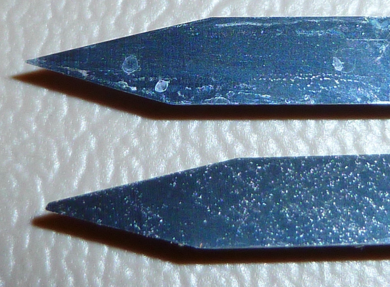
I'll replace it with the new one.
@neverdie
Just for future reference i would use a duff cutter for autolevelling then change to a good cutter to cut the job after resetting the z0.
It is so easy to smash the front of an engraving cutter when using this method for autolevelling as the machine takes a little time to stop after touching the pcb.
Just my advice anyway:relaxed: -
@neverdie
Just for future reference i would use a duff cutter for autolevelling then change to a good cutter to cut the job after resetting the z0.
It is so easy to smash the front of an engraving cutter when using this method for autolevelling as the machine takes a little time to stop after touching the pcb.
Just my advice anyway:relaxed:@rmtucker said in CNC PCB milling:
Just for future reference i would use a duff cutter for autolevelling then change to a good cutter to cut the job after resetting the z0.
What's a "duff cutter"? Did you mean "dull cutter"?
-
@rmtucker said in CNC PCB milling:
Just for future reference i would use a duff cutter for autolevelling then change to a good cutter to cut the job after resetting the z0.
What's a "duff cutter"? Did you mean "dull cutter"?
-
Argh. I ran the job, and the first cut went great. All subsequent cuts though didn't penetrate the surface:
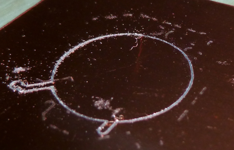
Afterward, when I checked the zero on z, I found that it was off by 0.049. That explains it, since the cut-depth was 0.05.I'll re-zero and try running the same job again.
-
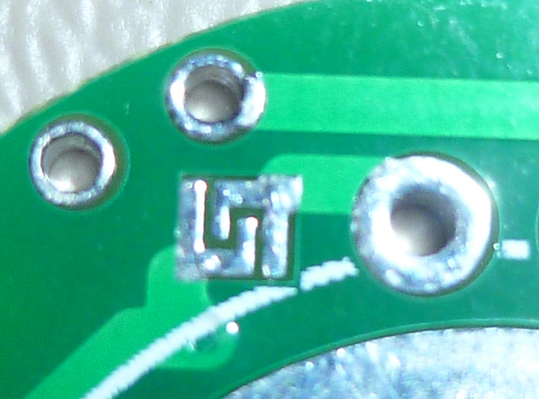
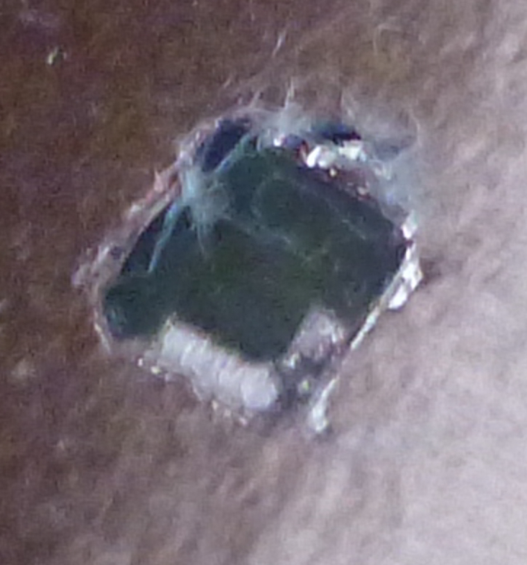
That made a much better result:
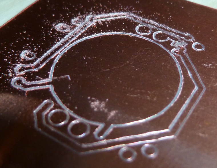
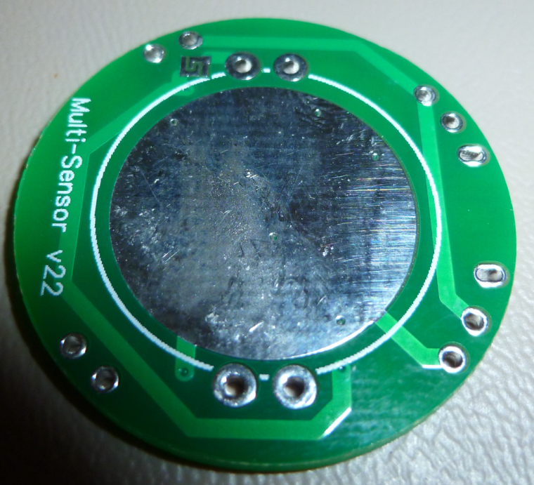
It corresponds to this as the actual PCB:
-
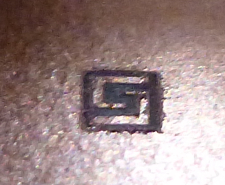
However, what's telling is that it obliterated the traces on either side of a 6 mil separation:
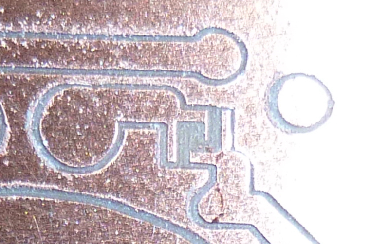
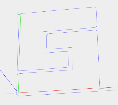
This is how it should look instead:
So, what happened?
My current hypothesis: the first cutting sheared 0.049mm off the tip of the blade, making it wider than it should be. Then, after re-zeroing, the wider blade cut too wide as it cut the traces for the solder jumper.
Is that reasonable, or is there a better hypothesis?
If it's true, then what do I do about it? Perhaps use a higher quality bit than the freebie that came with the kit?
Actually, I'm not even sure what the dimensions were on the freebie. It wasn't labeled. Perhaps it was too wide to begin with.
-
Well, to explore this more, I think I'll create a test board consisting purely of a few solder jumpers. That way I can put the focus directly on the 6 mil issue and won't be wasting time on etching that's unrelated to that.
-
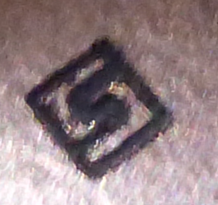
Doing just a single solder jumper, with the same bit, and autoleveling every 1mm, the result is:
which is pretty close, actually. Looks like maybe the bit is a little too wide, or else there's runout which is making it appear wider than it actually is.I'll try it with a fresh bit next and see if it improves.
-
Well, that went horribly:
and I have no idea why: -
I tried again with the same bit, after removing and re-inserting it. Got a better result this time:
Unless someone has suggestions on how to tweak this, I think that may represent approximately the best this CNC can do.
-
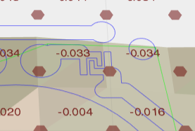
In truth, though, I think it may be a flawed gcode algorithm:
Instead of two separate cutting passes through the center section, one would do, and would produce a better result.How to tweak flatcam to do that? I probably haven't configured flatcam correctly. i.e. user error.
-
However, what's telling is that it obliterated the traces on either side of a 6 mil separation:
This is how it should look instead:
So, what happened?
My current hypothesis: the first cutting sheared 0.049mm off the tip of the blade, making it wider than it should be. Then, after re-zeroing, the wider blade cut too wide as it cut the traces for the solder jumper.
Is that reasonable, or is there a better hypothesis?
If it's true, then what do I do about it? Perhaps use a higher quality bit than the freebie that came with the kit?
Actually, I'm not even sure what the dimensions were on the freebie. It wasn't labeled. Perhaps it was too wide to begin with.
@neverdie said in CNC PCB milling:
Actually, I'm not even sure what the dimensions were on the freebie. It wasn't labeled. Perhaps it was too wide to begin with.
Maybe this is where your problem lies.
How did you write the g-code without knowing?
Too many variables here wich could give you these results.
The bigger tracks,Are they measuring the correct width with a vernier after you have cut them? -
I assumed the width on the freebies was 0.1mm, because that's what was advertised on Jack's posting for the machine. However, I don't know how to verify that, so the uncertainty comes in whether Jack actually delivered what was advertised or slipped in something else. I chose to give Jack the benefit of the doubt.
-
If I were to enter a wider tool diameter of 0.155mm (instead of 0.1mm) into flatcam, I think I can coax flatcam into generating better g-code for this situation. I'll do that and then post the results.
-
Doing just a single solder jumper, with the same bit, and autoleveling every 1mm, the result is:
which is pretty close, actually. Looks like maybe the bit is a little too wide, or else there's runout which is making it appear wider than it actually is.I'll try it with a fresh bit next and see if it improves.
-
No improvement really:
I think this means that the effective cutting width is actually greater than that, either from the bit itself or from runout or from who knows what else.
Probably nothing I can do about runout, except buy a different/better motor.
I'll have to wait for the etching bits from Aliexpress to try what is maybe (?) a proper 0.1mm etching bit. Like I say, I have no way of judging whether the freebies that came with the kit really are that or not, as I have nothing to compare.
By the way, my reason for picking the 0.155mm tool width in flat cam is that it produces this g-code path, which should have preserved more of the copper pad where it was being obliterated:
-
Yes you can. Get the gcode I've posted above, adjust for your feedrate, autolevel it in cp and give it a go. Really curious about the results.
-
@mfalkvidd said in CNC PCB milling:
@neverdie have you verified isolation between the parts? The cut is good?
Good question. I have doubts about how well I could measure it using calipers. However, maybe if I put the board onto a flatbed optical scanner, which would have a known DPI, I could measure the actual cut width with reasonable accuracy. I haven't done that yet, though.
-
@NeverDie Using traces one next to other at known distance you can determine the exact width of the engraving for a wanted depth of cut. I know you don't want to mess with gcode, but it's simpler than you think. Please look at the code: you have init (g92 for setting zero, g21 for mm, etc) you set the feedrate in mm/sec, you have a few movements (g0) a "dwell" to pierce the copper for 0.5seconds (g4) then some cutting moves (g1) all have absolute cartesian coordinates. Eg you're at (0,0) then g1 x0y10 means travel at (0,10) move only the y axis 10mm to the back of the machine, g1 x0.1y10 means move 0.1mm to the right, etc.
You have the whole script posted above, set your feedrate the same as you set in flatcam, and set the depth in the first z-0.1mm line, maybe you want 0.05mm for eg. After editing the file run it in cp with autoleveling and post the results.
Hello! It looks like you're interested in this conversation, but you don't have an account yet.
Getting fed up of having to scroll through the same posts each visit? When you register for an account, you'll always come back to exactly where you were before, and choose to be notified of new replies (either via email, or push notification). You'll also be able to save bookmarks and upvote posts to show your appreciation to other community members.
With your input, this post could be even better 💗
Register Login