CNC PCB milling
-
@neverdie Congrats for your result, I use a "copper pour" all over the board, that makes it pass at least 2 times, once for the track and once for the pour isolation. I never mess with flatcam's multiple passes, but I believe you can get the same results. What you see in the middle are copper "silvers" that is copper left behind between traces.
From the last picture of the width test is seems your bit is engraving 0.1mm wide.
Try to use OpenCNCPilot instead of Chillipeppr and set the lines to be split at 1-2mm lengths and probing each 2-3mm. That should make the engraving depth more uniform.
I see a couple copper flakes, maybe go even slower than 100? And give it a light sandpaper with 1000 grit or a scotchbrite sponge and some abrasive detergent for dishes?@executivul Thanks!
For the convenience of others reading this thread, here's a quick youtube:
https://www.youtube.com/watch?v=XDCu3cgOjCYI'm surprised to learn that not all auto levelers do it that way, because it seems like the only right way to do it. I'll give it a try.
-
Well, for some reason when I connect using OpoenCNCPilot, it turns the spindle on at maximum speed. I tried turning it off with the command 'S0', but it had no effect. So, I manually disconnected the wire that powers the spindle. Surely, there's a better way?
Anyhow, after doing that, I notice that the motors are making a really loud shrill sound, even though they're not moving. So, something is definitely FUBAR the moment I connect.
I had to disconnect and then connect using chilipeppr to have it all return to normal.
Maybe @andrew can try it? Perhaps there's a workaround that's not self-evident to me, but perhaps would be to someone else.
@neverdie OpenCNCPilot needs latest grbl 1.1f
-
OK, I'll resume the search for my dragon....
Meanwhile, I should be receiving my CNC drill bits and routing bits (to cut the board outline) fairly soon. Will I be using Chillipeppr to do those tasks (I'm guessing so) or something else?
-
OK, I'll resume the search for my dragon....
Meanwhile, I should be receiving my CNC drill bits and routing bits (to cut the board outline) fairly soon. Will I be using Chillipeppr to do those tasks (I'm guessing so) or something else?
@neverdie I have an idea, why don't you open the gcode in Opencncpilot, simplify it, split long moves, save it and then open in chillipeppr and do the probong and actual milling?
-
@neverdie I have an idea, why don't you open the gcode in Opencncpilot, simplify it, split long moves, save it and then open in chillipeppr and do the probong and actual milling?
@executivul Brilliant idea! Simplifying, the line count went from 3609 to 3608. Converting arcs to line segments had no effect. Then, splitting every 1mm, it went to 4114. I copied it into a new file, and now I'll see how it runs using chilipeppr.
-
Results look much better this time:
Using Chilipeppr, I probed every 3mm and then let it rip. As before, it was cutting at z=-0.1 and a feedrate of 76.2 (the feedrate wasn't a conscience choice but rather just what flatcam gave me, for whatever reason).The good news is that it doesn't have the blatantly obvious trace obliteration that it had the first time. All in all, it looks like a definite improvement. :)
@neverdie Seems like it's getting better, still some traces in the middle are hairthin, maybe increasing tool size in flatcam a tad? like 0.12mm so it lets the tracks be wider. Bare in mind this is a prototyping machine, I use mine for low batch home automation boards, under 20 boards of the same kind, at the price of a blank pcb I can buy 10 for the price of one fab made 100x150mm, not to speak of wait time.
After you are satisfied with the board is time to get some plumber's paste for soldering copper pipes, that is used for tinning, or maybe you can find some liquid tinning solution, but that's more expensive here, I use the paste.
Then some soldermask and some uv led strips to make an exposure unit and there you have your own pcb fab at home :sunglasses:
-
@neverdie Seems like it's getting better, still some traces in the middle are hairthin, maybe increasing tool size in flatcam a tad? like 0.12mm so it lets the tracks be wider. Bare in mind this is a prototyping machine, I use mine for low batch home automation boards, under 20 boards of the same kind, at the price of a blank pcb I can buy 10 for the price of one fab made 100x150mm, not to speak of wait time.
After you are satisfied with the board is time to get some plumber's paste for soldering copper pipes, that is used for tinning, or maybe you can find some liquid tinning solution, but that's more expensive here, I use the paste.
Then some soldermask and some uv led strips to make an exposure unit and there you have your own pcb fab at home :sunglasses:
@executivul How much overlap in flatcam are you using? I've been using zero. Would changing it to something non-zero help, or is it irrelevant?
-
@executivul How much overlap in flatcam are you using? I've been using zero. Would changing it to something non-zero help, or is it irrelevant?
@neverdie I never do multiple passes, so overlap is irrelevant to me...
-
When I probe at 2mm, it often randomly fails with messages like this:
Moving to {x:12,y:28}
probe failed, clear controller alarm before resuming
Paused
Working on probe for {x:12,y:26} Found lowest Z:0.17499999999999996
Paused
What is causing these "probe failed" to happen? And how exactly am I supposed to "clear controller alarm"? It always seems that I need to disconnect from the serial port and then reconnect to get any further movement. But if I do that, it clears the x,y,z positions, effectively preventing any kind of sensible resumption. :(
-
Argh, it just happened again. This time when doing 3mm probing.
Moving to {x:12,y:27}
probe failed, clear controller alarm before resuming
Paused
Working on probe for {x:12,y:24} Found lowest Z:0.23000000000000004
Paused
How does it even decide that a probe error has happened?
-
Argh, it just happened again. This time when doing 3mm probing.
Moving to {x:12,y:27}
probe failed, clear controller alarm before resuming
Paused
Working on probe for {x:12,y:24} Found lowest Z:0.23000000000000004
Paused
How does it even decide that a probe error has happened?
@neverdie timing racing condition is f*king spjs, ugly hack is to try to increase probing starting height from 0.5mm to 1.0mm
-
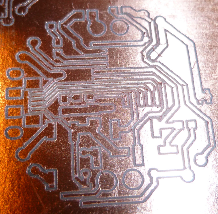
It's hard to photograph these etchings. They actually look better by eye. I tested out the last one with a continuity meter, and it seems that it would be functional (in the sense that the traces were isolated from what they should be and they connected the pads that they should.
However, without the solder mask, I'm doubtful those closely packed micro-usb pads on the middle left near the edge would be solderable without bridging.
I really hadn't considered I would ever need to do solder mask, I guess because the demo boards I've seen other people make don't seem to have it.
So, maybe a better question is: what is the minimum isolation width so that I won't need solder mask? Perhaps that becomes the limit for prototyping.
Anyhow, I'll look into it, but I really hadn't planned on taking that extra step.
-
They keep getting better!
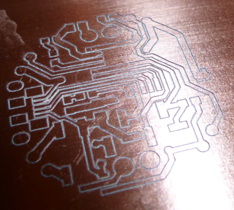
I used a fresh Jack bit to get this one. The tip on the bit used in the previous etching was a bit worn down, which I think explains the undesirable width of its cuts. I also dropped the feedrate to 50mm/minute, which may have helped also. Anyhow, most of the cuts seem very crisp compared to earlier attempts. As before, I split the line segments into 1mm lengths using the OpenCNCPilot. I think that is probably helping a lot.I did this one is two passes. The first pass was z=-0.05, and it didn't cut through enough of the copper. The second pass was z=-0.1, which is what you see above. Yet, some of the traces on the micro-usb on the middle left still don't seem fully isolated, so I'm about to try a third pass at z=-0.15
Also, this was the first job I ran with autoleveling set at 2mm. Perhaps that helped also.
-
I received my end-mill bits for cutting the PCB loose from the rest of the copper clad blank. Which got me thinking: since I have doubled sided tape on the back of the PCB blank, I presumably don't need mouse bites or similar, right? I should be able to just cut the board outline by cutting through to the sacrificial board underneath, right? Is that what others here are doing? Or are you milling tiny little supports that you break away at the end?
Regardless, what diameter end mill bit should I use for the task? What cutting depth? I'll look back to see if it's in @andrew 's list of magic numbers, but anyone else feel free to post what you like to use and do.
-
Here's what @andrew had to say:
edge cut or hole milling with the 0.8mm endmill:

feed rate: 170
z cut: -1.7mm
multi depth, depth/pass: 0.2mm
So, I guess by "z cut: -1.7mm", he likely meant that as a Z that's -1.7mm below the depth of the PCB? I'm not sure how else to interpret that.Hmmm.. I think he assumed the board thickness of 1.5mm, so he gave is 0.2mm more than that. Mine (being single sided) is 1.35mm, so I'll set cutting depth to 1.6mm, just to be sure.Aside from that, 0.8mm end mill and multiple passes at a feed rate of 170. So, I guess I use flatcam to produce the gcode that conforms to this and then run it in Chilipeppr.
And, it looks like flatcam adds the cut-out supports automatically. Nice.
-
Argh. Another probe failure:
Moving to {x:4.430000007152557,y:19.430000007152557}
probe failed, clear controller alarm before resuming
Paused
Working on probe for {x:4.430000007152557,y:24.430000007152557} Found lowest Z:0.051000000000000156
Paused
even though I have it set to start probing at z=1.0mm. This really needs to be fixed.
-
Unfortunately, I botched the third etching pass. My fault. But I decided to try the board cutout anyway:
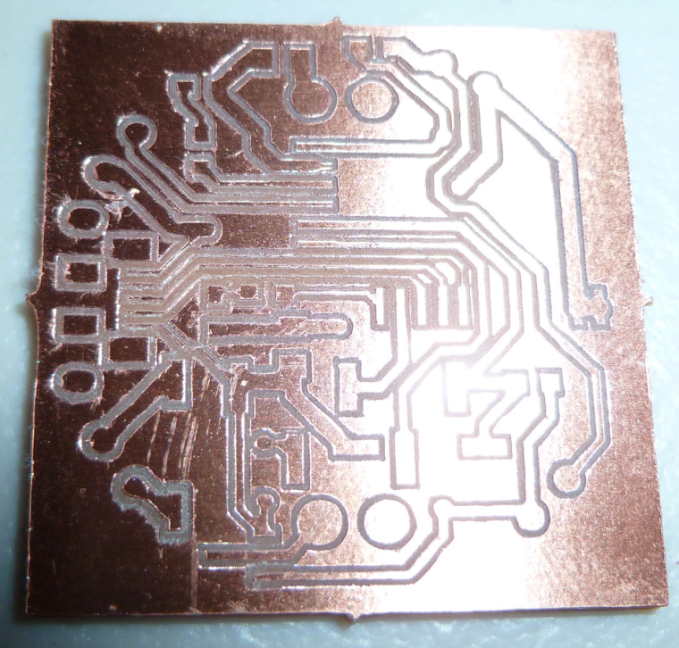
I didn't see a way for flatcam to do a circular cut-out, so I just went with the rectangular cut-out. Anyhow, it worked.
I receive my CNC drill bits on Friday, so after that I should be able to do a complete PCB of some kind. :)
Hello! It looks like you're interested in this conversation, but you don't have an account yet.
Getting fed up of having to scroll through the same posts each visit? When you register for an account, you'll always come back to exactly where you were before, and choose to be notified of new replies (either via email, or push notification). You'll also be able to save bookmarks and upvote posts to show your appreciation to other community members.
With your input, this post could be even better 💗
Register Login