Pellet burner Monitoring
-
I'm following-up on this thread Sensor for pellet burner.
On my side, I have started to monitor my pellet burner about 1-year ago.
I'm measuring global power consumption of the boiler as well as departure and return temperature of the heating circuit.
Even though, I do that since one year only, I've been thinking about how to monitor pellet consumption for at least 5 years (yeah, failure is an option :) ).
What I have tested:- IR sensor on the fan of the pellet convoying motor: it failed because it was too far
- Magnetic sensor on this same fan: same failure for the same reason
- Vibration sensor: the heater vibrates ...all the time :)
Now, I'm about to test something quite simple: mains presence at the convoying motor. This one is quite easy (I will show you how) to design and relates quite easily to the pellet consumption: 1 second equals x grams of pellet.
How do I know the time mains are activating the motor ? Well, a zero-crossing detector.
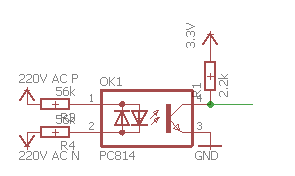
Beware, main resistance values are key: they depend on mains value, optocoupler characteristics and ..their power. Using the displayed value (56k) will keep the power under 1/4W. The optocoupler is a LTV-814 (cheap and efficient !).
Here is a quick schema of such a detector. I will keep you posted with the results.
Hope my experience will help others.
QQ.
-
I'm following-up on this thread Sensor for pellet burner.
On my side, I have started to monitor my pellet burner about 1-year ago.
I'm measuring global power consumption of the boiler as well as departure and return temperature of the heating circuit.
Even though, I do that since one year only, I've been thinking about how to monitor pellet consumption for at least 5 years (yeah, failure is an option :) ).
What I have tested:- IR sensor on the fan of the pellet convoying motor: it failed because it was too far
- Magnetic sensor on this same fan: same failure for the same reason
- Vibration sensor: the heater vibrates ...all the time :)
Now, I'm about to test something quite simple: mains presence at the convoying motor. This one is quite easy (I will show you how) to design and relates quite easily to the pellet consumption: 1 second equals x grams of pellet.
How do I know the time mains are activating the motor ? Well, a zero-crossing detector.
Beware, main resistance values are key: they depend on mains value, optocoupler characteristics and ..their power. Using the displayed value (56k) will keep the power under 1/4W. The optocoupler is a LTV-814 (cheap and efficient !).
Here is a quick schema of such a detector. I will keep you posted with the results.
Hope my experience will help others.
QQ.
-
Maybe I'm missing something, but why not using a clamp current sensor so you don't have to mess with mains ?
I think the vibration sensor was not a bad idea, but should be done with an accelerometer. Then you could set a minimum vibration threshold based on the "action" of your pellet burner that is of interest for you ?
-
With please. Here is a global schema of the pellet burner:
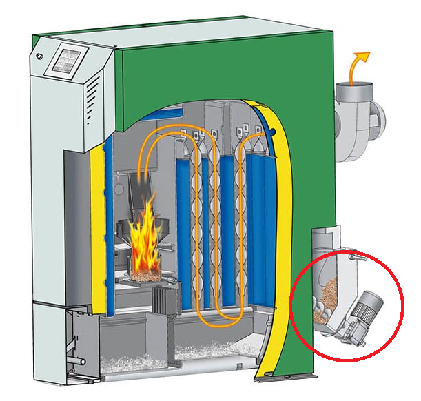
I have circled the part displaying the beginning of the pellet conveyor and the motor.
@qqlapraline I don't quite see the logic here, you are looking at checking a mechanical output but from electrical behaviour, or am I completely missing the objective?
Most pellet feed archimidean screw drives I've seen have the drive shaft extend beyond the gearbox, even if only a short stub to which you could attach a rotational sensor or a magnet... Short of shearing the shaft, detecting shaft rotation at that end should be 100%, no?.
Failing that, there is usually a flat plate at the start of the shaft where the feed comes in to prevent clogging or choking, perhaps the passing of the paddle could be detected, giving you turns per whatever? -
something else, can't you measure the pellet storage tank with an ultrasonic range?, as times go by you can measure the hight is increasing (If the sensor is on the top lid)
and then I would measure the smoke temperature with a KTY sensor, as those can withstand around 1.000degree C.
Depending of your specific pellet boiler it might always have a little fire, some can self ignite the fire with a ceramic heatcoildoes your pellet tank looks like this?
http://midtfyns-montage.dk/wp-content/uploads/2016/12/Snegl-SCOTTE.jpg -
@Nca78, actually, I did not want to touch the existing cables to avoid any claim from the maintenance guy ;) And as I could not access one single wire, I had to find another way. Interesting enough, using the existing connecting screws was easier.
@zboblamont: the picture is quite not clear but the motor is very well protected to avoid any mechanical injury. And, probably as a consequence, there is not detectable magnetic field coming out of it.
@bjacobse: I have considered this as well (as well as some kind of a gauge based on pressure or anything else in the tank). But, unfortunatly, as this is a 7 tons / 11 m3 pellet tank, it is filled by a truck blowing pellets into it....making the life of the ultrasonic sensor really not long :)
Furthermore, ultrasonic sensor would be good to measure a level with a very large error margin. With my sensor, I will be close to a 1-gram quantum...measuring the current consumption very accurately.
For the story of it, I already have a way to measure pellet consumption in a rough approximation: but weighting the ashes :) :)QQ.
-
@Nca78, actually, I did not want to touch the existing cables to avoid any claim from the maintenance guy ;) And as I could not access one single wire, I had to find another way. Interesting enough, using the existing connecting screws was easier.
@zboblamont: the picture is quite not clear but the motor is very well protected to avoid any mechanical injury. And, probably as a consequence, there is not detectable magnetic field coming out of it.
@bjacobse: I have considered this as well (as well as some kind of a gauge based on pressure or anything else in the tank). But, unfortunatly, as this is a 7 tons / 11 m3 pellet tank, it is filled by a truck blowing pellets into it....making the life of the ultrasonic sensor really not long :)
Furthermore, ultrasonic sensor would be good to measure a level with a very large error margin. With my sensor, I will be close to a 1-gram quantum...measuring the current consumption very accurately.
For the story of it, I already have a way to measure pellet consumption in a rough approximation: but weighting the ashes :) :)QQ.
@qqlapraline I think you were replying to @gohan suggestion.
Is neither end of the shaft exposed or are they both shrouded?
Interesting solution though.... -
@Nca78, actually, I did not want to touch the existing cables to avoid any claim from the maintenance guy ;) And as I could not access one single wire, I had to find another way. Interesting enough, using the existing connecting screws was easier.
@zboblamont: the picture is quite not clear but the motor is very well protected to avoid any mechanical injury. And, probably as a consequence, there is not detectable magnetic field coming out of it.
@bjacobse: I have considered this as well (as well as some kind of a gauge based on pressure or anything else in the tank). But, unfortunatly, as this is a 7 tons / 11 m3 pellet tank, it is filled by a truck blowing pellets into it....making the life of the ultrasonic sensor really not long :)
Furthermore, ultrasonic sensor would be good to measure a level with a very large error margin. With my sensor, I will be close to a 1-gram quantum...measuring the current consumption very accurately.
For the story of it, I already have a way to measure pellet consumption in a rough approximation: but weighting the ashes :) :)QQ.
-
@zboblamont : it's not exposed under the tank and totally shrouded on the boiler side
@gohan: right, by I really don't want to touch the wires. And neutral and phase are inside a single cable with not enough space to put a clamp..;)
-
Yep ! And that's why it's fun ! :)
But my zc detector will work too. My first tests are OK :)QQ.
-
After a 4 years work, here are some samples of my pellet consumption.
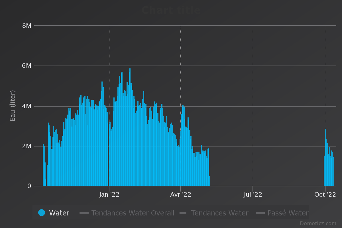

Now, guess when I usually stop the boiler ..:)
Cheers,
QQ.
Hello! It looks like you're interested in this conversation, but you don't have an account yet.
Getting fed up of having to scroll through the same posts each visit? When you register for an account, you'll always come back to exactly where you were before, and choose to be notified of new replies (either via email, or push notification). You'll also be able to save bookmarks and upvote posts to show your appreciation to other community members.
With your input, this post could be even better 💗
Register Login