💬 Multi-Sensor: Temp/Humidity/PIR/ Leak/Magnet/Light/Accel
-
@neverdie said in 💬 Multi-Sensor: Temp/Humidity/PIR/ Leak/Magnet/Light/Accel:
Doing that, and using this script, I think it will be audible if you're in the same room as it (and if the room is otherwise quiet).
Guess this is not made for Vietnam then :D
I supposed this type of buzzer is made more for user feedback for things like touch sensors, than for raising alert. -
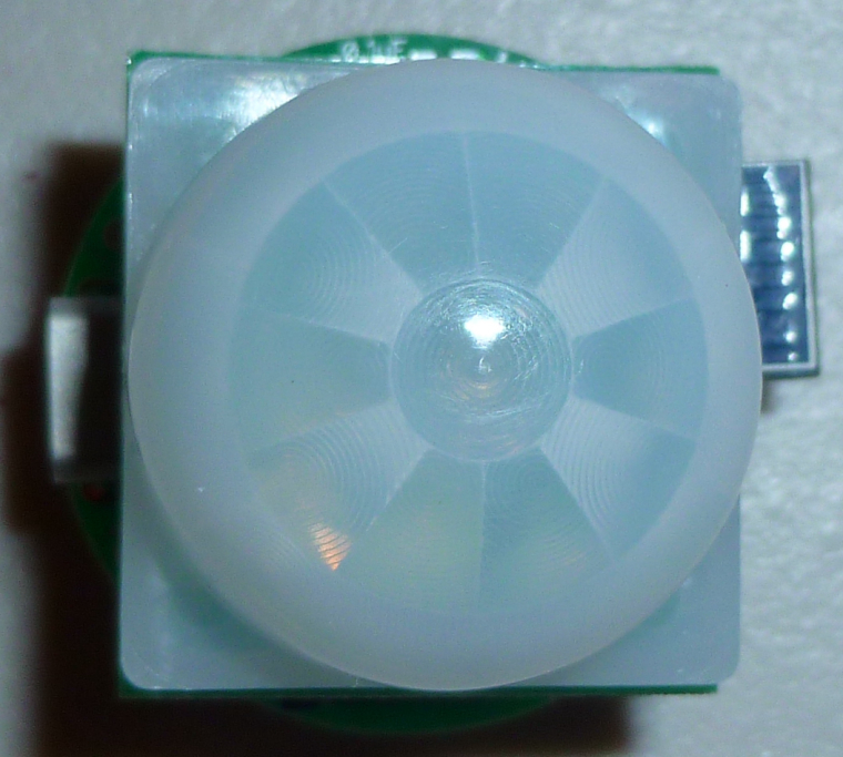
Here's the latest version of the PIR sensor embodiment:
It runs from two CR2032's.Very compact! :)
-
Here's the latest version of the PIR sensor embodiment:
It runs from two CR2032's.Very compact! :)
@neverdie how do you connect thr two Cr batteries ?
Another question ? I read in another comments that you need 100-200 uF capacitor so that the radio can work since thr CR battery wont be strong enough. Did you add this ?
-
@neverdie how do you connect thr two Cr batteries ?
Another question ? I read in another comments that you need 100-200 uF capacitor so that the radio can work since thr CR battery wont be strong enough. Did you add this ?
@ahmedadelhosni said in 💬 Multi-Sensor: Temp/Humidity/PIR/ Leak/Magnet/Light/Accel:
how do you connect thr two Cr batteries ?
This was recently discussed in the Bluetooth action! thread.
-
@nca78 What strange is that if I cup my hand over it, it actually becomes louder. Not sure what's up with that. So, maybe I'm just not driving it right.
@neverdie said in 💬 Multi-Sensor: Temp/Humidity/PIR/ Leak/Magnet/Light/Accel:
@nca78 What strange is that if I cup my hand over it, it actually becomes louder. Not sure what's up with that. So, maybe I'm just not driving it right.
Isn't that the principle for most speakers, using a sound box ?
-
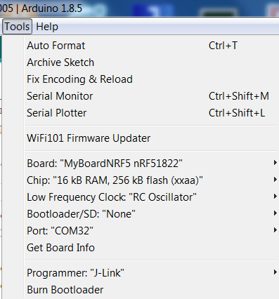
Wich board do you use in arduino? I can only use Waveshare BLE4.0. At Generic etc. It seems, that the oscillator doesn't work probably.
@tiwo85 said in 💬 Multi-Sensor: Temp/Humidity/PIR/ Leak/Magnet/Light/Accel:
Wich board do you use in arduino? I
Not sure what you're asking.
-
@tiwo85 said in 💬 Multi-Sensor: Temp/Humidity/PIR/ Leak/Magnet/Light/Accel:
Wich board do you use in arduino? I
Not sure what you're asking.
-
@neverdie I mean this:
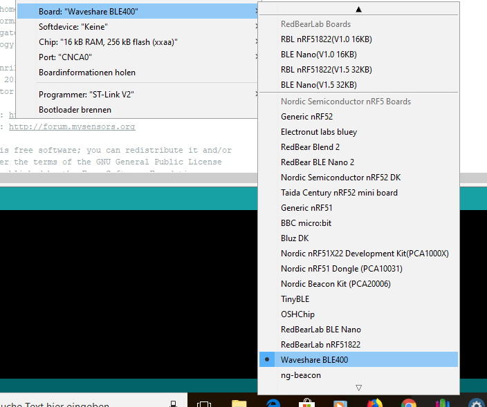
When I use Generic nRF51 or something else, the onboard LED turns on and doesn't turns off. When I use Waveshare BLE400 the sketch works as usual -
For PIR capability, the multi-sensor can simply plug into this PIR module: https://www.openhardware.io/view/420/AM612-Passive-Infrared-Sensor-Breakout-Board
-
@neverdie do you have a working example sketch. I try the example sketch from the 10years pir sensor an d modify a little bit, but it doesn't work. The sketch awake every 5 minutes and send the state from the pir and that's it.
-
@neverdie thank you. I made this sketch work. But I need to get work interrupts. I use your code for the am612, but it doesn't work. Then I use the example from Redbear labs "Example interrupted" to turn on the led when p0.02 is high. I use Mysensors library and set My Core only. Then it runs. But when I try to integrate Mysensors routines "presentation" etc. And disable "my core only" , then the interrupt doesn't work.
// SUMMARY: This demo sketch runs on the AM612 PIR v607 PCBto transmit battery voltage (heartbeat) and motion detections to a MySensors gateway using MySensors protocols. // Note: because this is a passive node, node ID must be set manually to a unique sensor node ID: #define MY_NODE_ID 143 // Passive mode requires static node ID //#define MY_CORE_ONLY #define MY_PASSIVE_NODE #define MY_RADIO_NRF5_ESB /** * The MySensors Arduino library handles the wireless radio link and protocol * between your home built sensors/actuators and HA controller of choice. * The sensors forms a self healing radio network with optional repeaters. Each * repeater and gateway builds a routing tables in EEPROM which keeps track of the * network topology allowing messages to be routed to nodes. * * Created by Henrik Ekblad <henrik.ekblad@mysensors.org> * Copyright (C) 2013-2017 Sensnology AB * Full contributor list: https://github.com/mysensors/Arduino/graphs/contributors * * Documentation: http://www.mysensors.org * Support Forum: http://forum.mysensors.org * * This program is free software; you can redistribute it and/or * modify it under the terms of the GNU General Public License * version 2 as published by the Free Software Foundation. * ******************************* * * REVISION HISTORY * Version 1.0 - tekka * * DESCRIPTION * Passive node example: This is a passive & independent reporting node * */ // This demo sketch also draws from the MySensor's example MotionSensor sketch. #define IS_NRF51 //true iff the target is an nRF51. If an nRF52, then comment this line out! #define SHORT_WAIT 50 // Enable debug prints //#define MY_DEBUG #define PIN_LED1 (4) // 4 is sensor LED , 1 is onboard LED #define LED_BUILTIN PIN_LED1 #define PIN_SENSOR1 (10) // 2 is waterleak, 10 is PIR , 3 is Pin5/INT #define SENSOR1 PIN_SENSOR1 #include <MySensors.h> //#define CHILD_ID_TEMP 1 //definitions contributed by smilvert (see above credit) #define CHILD_ID 2 // Id of the motion sensor child #define ID_S_MULTIMETER 28 // Initialize general message //MyMessage msgTemp(CHILD_ID_TEMP, V_TEMP); MyMessage msg(CHILD_ID, V_TRIPPED); MyMessage msg_S_MULTIMETER_V_VOLTAGE(ID_S_MULTIMETER,V_VOLTAGE); float batteryVoltage=0; /*#include "nrf_temp.h" float read_temp_value(){ float temp=0; // Starten Sie die Temperaturmessung. NRF_TEMP->TASKS_START = 1; // Warten Sie, bis die Temperaturmessung abgeschlossen ist. while (NRF_TEMP->EVENTS_DATARDY == 0){ // Do nothing.} } NRF_TEMP->EVENTS_DATARDY = 0; // Lesen Sie den Temperaturwert vom Sensor ab // Die Genauigkeit beträgt 0,25 Grad Celsius <=> 1 Einheit = 0,25 Grad Celsius // Teile durch 4, um einen C-Wert zu erhalten temp = ((float)nrf_temp_read() / 4.); // Hoàn thành quá trình đo. NRF_TEMP->TASKS_STOP = 1; return temp; }*/ void blinkityBlink(uint8_t repetitions) { for (int x=0;x<repetitions;x++) { digitalWrite(LED_BUILTIN ,HIGH); delay(20); digitalWrite(LED_BUILTIN ,LOW); delay(100); digitalWrite(LED_BUILTIN ,HIGH); delay(20); digitalWrite(LED_BUILTIN ,LOW); if (x<(repetitions-1)) { //skip waiting at the end of the final repetition delay(500); } } } void handle_irq3(void) { if(HIGH == digitalRead(SENSOR1)){ digitalWrite(LED_BUILTIN , HIGH); send(msg.set("1")); // motion detected } else { digitalWrite(LED_BUILTIN , LOW); send(msg.set("0")); // send all-clear to prepare for future detections } } void presentation() { // Send the sketch version information to the gateway and Controller sendSketchInfo("NRF Motion Sensor", "1.0"); // wait(SHORT_WAIT); // present(CHILD_ID_TEMP, S_TEMP,"Onboard Temperature"); wait(SHORT_WAIT); // Register all sensors to gw (they will be created as child devices) present(CHILD_ID, S_MOTION,"Motion Sensor"); wait(SHORT_WAIT); present(ID_S_MULTIMETER,S_MULTIMETER,"Electric Station"); wait(SHORT_WAIT); } void setup() { // put your setup code here, to run once: //hwInit(); //hwPinMode(LED_BUILTIN,OUTPUT_D0H1); //hwPinMode(SENSOR1,INPUT); //nrf_temp_init(); pinMode(LED_BUILTIN , OUTPUT); digitalWrite(LED_BUILTIN , LOW); blinkityBlink(5); //signify power-up and start of operations // set interrupts, pin default is HIGH attachInterrupt(SENSOR1, handle_irq3, CHANGE); } void loop() { // put your main code here, to run repeatedly: //send(msgTemp.set(read_temp_value(),2)); batteryVoltage=((float)hwCPUVoltage())/1000.0; //take voltage measurement after transmission to hopefully measure lowest voltage that occurs. send(msg_S_MULTIMETER_V_VOLTAGE.set(batteryVoltage,3)); //send battery voltage with 3 decimal places sleep(900000); //sleep 15 min } -
Hi,
I like to buy this board and your AM612 breakout pcb through hardware.io.
But first I have few questions unfortunately I couldn't find the answers here in this thread/forum.
-
I assume this board has to be programmed via the 10pin box header. How can I connect it to my computer? I think there is some adapter or similar required? Any selfmade options available? In this thread I saw that it should be possible to program this device via the Arduino IDE?
-
Can I mount the following sensors at the same time without space conflicts:
- Motion PIR (AM612breakout)
- Temp + Humidity
- Light
-
Does this board have some free digital pins for door contact and or relais? (if yes, how many?)
-
(Optional) I think there are no MISO/MOSI/... pins for connecting a RFM69 module?
I don't like to use the battery option. I will power the board via power supply. Can I connect a 5V power supply to the battery pins or what is the best option?
Thanks in advance.
-
-
Hi,
I like to buy this board and your AM612 breakout pcb through hardware.io.
But first I have few questions unfortunately I couldn't find the answers here in this thread/forum.
-
I assume this board has to be programmed via the 10pin box header. How can I connect it to my computer? I think there is some adapter or similar required? Any selfmade options available? In this thread I saw that it should be possible to program this device via the Arduino IDE?
-
Can I mount the following sensors at the same time without space conflicts:
- Motion PIR (AM612breakout)
- Temp + Humidity
- Light
-
Does this board have some free digital pins for door contact and or relais? (if yes, how many?)
-
(Optional) I think there are no MISO/MOSI/... pins for connecting a RFM69 module?
I don't like to use the battery option. I will power the board via power supply. Can I connect a 5V power supply to the battery pins or what is the best option?
Thanks in advance.
Hello @ehome
-
it is based on an arduino pro mini (NModule board, don't forget that this is just a shield for NModule) , so you program the arduino pro-mini, usually using an FTDI adapter. You should find plenty of explanations online.
For programming bootloader/fuses, you can use and arduino nano with the ArduinoISP sketch: MOSI=>MOSI, MISO=>MISO, SCK=>SCK and SS (pin 10) of nano to reset pin of the pro mini. Here also you will find plenty of examples/videos etc online.
Start with reading the page about NModule:
https://www.openhardware.io/view/364/NModule -
In theory yes if light sensor is on the AM612 breakout. I will test this configuration next week and confirm to you that it is working before you order the board. If you don't hear any news about that before the end of next week ring me a bell here as it probably means I forgot :)
-
You will use one of the external interrupt pins (pin 3) for the PIR sensor, so you will have one left (pin 2). If you don't use the leds there are 3 other input pins available on the NModule connector (A1,A2,A3, you can use them as digital inputs too), on battery powered sensors it needs pin change interrupts, but as you are using a power supply it won't be a problem.
-
No you can't connect a RFM module, NModule is only for SMD NRF24 modules
-
You should connect power to RAW and GND pins on the NModule connector. The best is to use AMS1117 regulator to get the 3.3V, it's probably overkill for your usage but it's very stable and will filter the noise of your power supply much better than the XC6206 (which more suitable for a li-ion powered node). In addition you will be able to use a power supply up to 12V
-
-
@ehome said in 💬 Multi-Sensor: Temp/Humidity/PIR/ Leak/Magnet/Light/Accel:
@Nca78 many thanks for your answer. Maybe may question was a little bit too vague. I didn't mean the NMODULE board. I was speaking about the NRF51xxx board from @NeverDie
These are shield made to work with the NModule. For the same sensors I think @NeverDie has what you need in NRF5 versions, so ask him on the right thread :)
-
-
I've downloaded the source files and tried to compile them.
I got fatal error: sketch/MyBoardNRF5.h: No such file or directory -
Then I renamed MyNRF5Board.h to MyBoardNRF5.h
I got #error No forward link or gateway feature activated. This means nowhere to send messages! Pretty pointless. -
Then I added #define MY_GATEWAY_SERIAL into the code
I got many errors i.e. 'PIN_AIN0' was not declared in this scope
How to compile the downloaded source files?
-
-
Hi,
What is the power consumption you get with this board and i2c sensors? I built several boards and measured the consumption using a INA219 sensor (lowest resolution is 0.1mA). Without any I2C sensor initialized, it shows a power consumption well below 0.1mA (i.e. it always shows 0.0), but as soon as I use an I2C sensor, the consumption during sleep increases to 0.3mA, which drains the battery faster than desired for a battery node...I tried it with several different implementations / sensors, and always got the same result:
- MyBoardNRF5 with BME280 (Adafruit library), sketch adapted from the one supplied with this board
- MyBoardNRF5 with BME280 using NodeManger
- MyBoardNRF5 with VL53L0x using NodeManager
- Custom board in Arduino IDE derived from Sandeep Mistry's generic 51822 board, with either of the above sketches
Is there anything special I need to do to get power consumption with i2c sensors down to the desired single-digit-µA-range during sleep?
Hello! It looks like you're interested in this conversation, but you don't have an account yet.
Getting fed up of having to scroll through the same posts each visit? When you register for an account, you'll always come back to exactly where you were before, and choose to be notified of new replies (either via email, or push notification). You'll also be able to save bookmarks and upvote posts to show your appreciation to other community members.
With your input, this post could be even better 💗
Register Login