DIY CNC mill from mainly salvaged and 3D printed parts

-
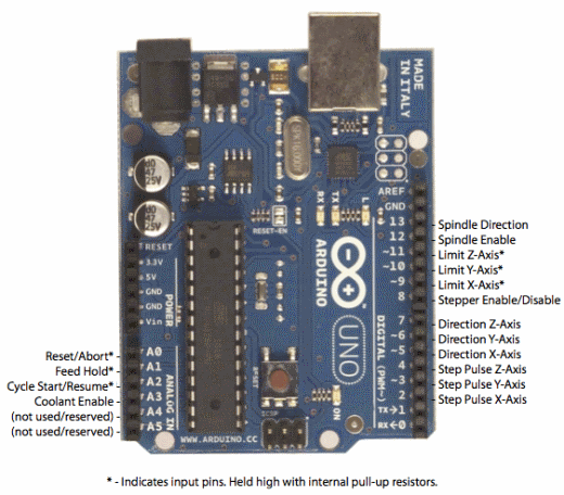
So, I was doing some reading on how to use auto-leveling with GRBL and the CNC shield that I have. What I read was that for GRBL on an arduino, the probe needed to be connected to analog pin 5 and ground. For the shield that I have, this is the arduino pinout that I found on it:
Turns out that A5 is not connected on my shield and is labeled (not used/reserved). Luckily, in my parts bin I had a couple arduino uno prototyping boards. So I made a board that stacks in between the CNC shield and the uno. Here is the board with the probe attached:
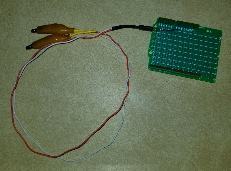
The probe wires are made from an old dupont header cable that was salvaged out of an old PC. I figured that fit right in with the theme of the project.And here is the stack.
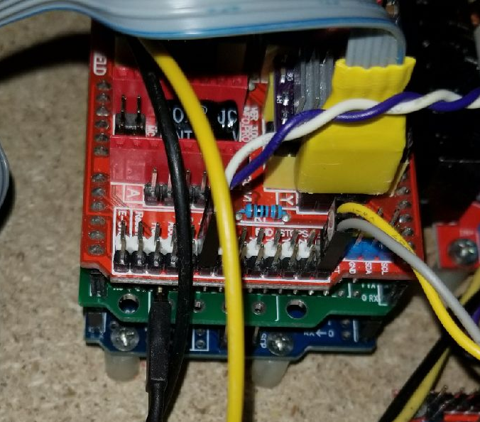
I did a test and the probe seems to work. Tomorrow I will probably do a test mill of a small pcb to see how that works out.For a junk parts build, I am pretty happy with the way it is turning out.
-
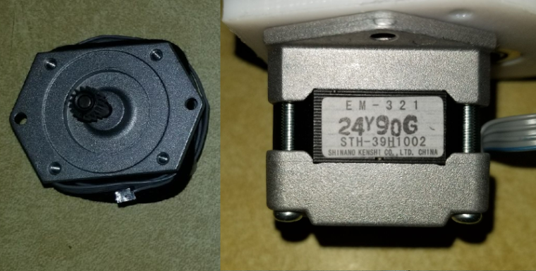
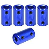
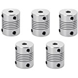
So, turns out the shaft couplers that I got are kind of crappy and seem to come loose every so often. These are the ones that I got which have their set screws on opposite sides from each other:
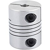
I am looking to get some replacements, but am wondering which style would be best to get. There is this style which has set screws at 90 degrees to each other:
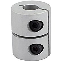
There is this style which actually clamps around the shaft:
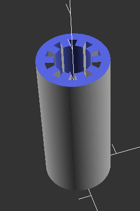
Then there is this style that also is a clamp style which says that it is somewhat flexible. The thing with this style is that I don't know if it separates at the red part:
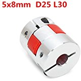
The shaft on my stepper is a D shaft, so I am wondering how well the clamp style ones will work, at least on the motor side. The lead screw is round, so that should be fine for the one clamp.
Any thoughts?
-
So, turns out the shaft couplers that I got are kind of crappy and seem to come loose every so often. These are the ones that I got which have their set screws on opposite sides from each other:
I am looking to get some replacements, but am wondering which style would be best to get. There is this style which has set screws at 90 degrees to each other:
There is this style which actually clamps around the shaft:
Then there is this style that also is a clamp style which says that it is somewhat flexible. The thing with this style is that I don't know if it separates at the red part:
The shaft on my stepper is a D shaft, so I am wondering how well the clamp style ones will work, at least on the motor side. The lead screw is round, so that should be fine for the one clamp.
Any thoughts?
-
@dbemowsk My kit came with the same blue couplers, and they came loose too. However, loctite fixed the problem.
-
I believe the flexible couplers are for when the stepper axis isn't co-linear with the threaded rod.
-
I believe the flexible couplers are for when the stepper axis isn't co-linear with the threaded rod.
-
@neverdie I still may buy another set. I think the clamping style would be the best, but as I said, not sure how that would be on the D shaft.
-
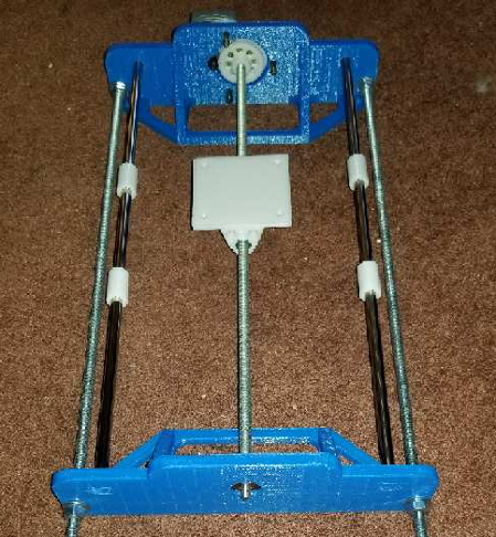
BTW, I suspect that using longer linear bearings will lead to less slop:
http://a.co/0yWkPgi -
BTW, I suspect that using longer linear bearings will lead to less slop:
http://a.co/0yWkPgi@neverdie said in DIY CNC mill from mainly salvaged and 3D printed parts:
@dbemowsk Are these not something you can 3D print? Then you could customize to the D shaft if you like.
I guess I hadn't thought about 3D printing them. I did order a pack of two though.
https://www.amazon.com/uxcell-Encoder-Coupler-Coupling-8mmx5mm/dp/B01E0CTI42/ref=sr_1_14?ie=UTF8&qid=1522050398&sr=8-14&keywords=5mm+8mm+coupler
@neverdie said in DIY CNC mill from mainly salvaged and 3D printed parts:
BTW, I suspect that using longer linear bearings will lead to less slop:
I would tend to agree. Does your CNC use linear bearings? -
@neverdie said in DIY CNC mill from mainly salvaged and 3D printed parts:
@dbemowsk Are these not something you can 3D print? Then you could customize to the D shaft if you like.
I guess I hadn't thought about 3D printing them. I did order a pack of two though.
https://www.amazon.com/uxcell-Encoder-Coupler-Coupling-8mmx5mm/dp/B01E0CTI42/ref=sr_1_14?ie=UTF8&qid=1522050398&sr=8-14&keywords=5mm+8mm+coupler
@neverdie said in DIY CNC mill from mainly salvaged and 3D printed parts:
BTW, I suspect that using longer linear bearings will lead to less slop:
I would tend to agree. Does your CNC use linear bearings?@dbemowsk said in DIY CNC mill from mainly salvaged and 3D printed parts:
Does your CNC use linear bearings?
Yes.
-
Just a note to everyone. These style couplers are NOT good for the X axis, or Z axis if the motor is vertical and facing down.

The problem is that the spiral part is actually quite springy. When say the X axis motor spins to pull the X axis to one side, the springy part seems to really stretch. Pushing the X axis works fine. Since my Z axis motor is mounted on top with the weight of the axis being downward, this will cause the coupler to stretch even more. My 3D printer uses these on it's Z axis which works fine because the motors face up with the pressure of the Z axis down on the couplers.The only thing about the ones that I got that I liked was the way that it clamps to the shaft. I think the clamping action is better because you get more surface area grabbing the shaft.
Something like this may be the best because it is solid and there is no stretching. It also has the clamping action.
-
Just a note to everyone. These style couplers are NOT good for the X axis, or Z axis if the motor is vertical and facing down.
The problem is that the spiral part is actually quite springy. When say the X axis motor spins to pull the X axis to one side, the springy part seems to really stretch. Pushing the X axis works fine. Since my Z axis motor is mounted on top with the weight of the axis being downward, this will cause the coupler to stretch even more. My 3D printer uses these on it's Z axis which works fine because the motors face up with the pressure of the Z axis down on the couplers.The only thing about the ones that I got that I liked was the way that it clamps to the shaft. I think the clamping action is better because you get more surface area grabbing the shaft.
Something like this may be the best because it is solid and there is no stretching. It also has the clamping action.
@dbemowsk they should work if used as intended. These couplings are supposed to be stiff in only one direction of freedom: Rotation of the axis (=transfer the torque of the motor to the axis). The other 5 degrees of freedom should be of low stiffness to absorb misalignment between motor and axis. So the correct type of bearings should actually constrain the axis to only rotate in one DoF and not translate into the coupling.
-
@dbemowsk they should work if used as intended. These couplings are supposed to be stiff in only one direction of freedom: Rotation of the axis (=transfer the torque of the motor to the axis). The other 5 degrees of freedom should be of low stiffness to absorb misalignment between motor and axis. So the correct type of bearings should actually constrain the axis to only rotate in one DoF and not translate into the coupling.
@technovation DIDn't think about that when I bought them. I will save them for spares for my 3D printer.
-
I notice that the kit from CNCrouterParts does appear to use the springy couplers:
https://www.youtube.com/watch?v=EiOOrOfwKvwSo, I guess it can't be bad, because they seem to make very nice kits.
Hello! It looks like you're interested in this conversation, but you don't have an account yet.
Getting fed up of having to scroll through the same posts each visit? When you register for an account, you'll always come back to exactly where you were before, and choose to be notified of new replies (either via email, or push notification). You'll also be able to save bookmarks and upvote posts to show your appreciation to other community members.
With your input, this post could be even better 💗
Register Login