Minimal design thoughts


  • Hero Member

    @tbowmo said:

    Seems like dirty pcb is doing a great job, compared to the price, only have experience with prinline.dk from previous jobs, but they are expensive like hell (just looked at their prices earlier today, together with Hek, They want 314$ (plus taxes) for the same job, that I pay 14$ for at dirtypcb, only advantage is that they have a turn arround time of 8 days, instead of 4-5 weeks from dirtypcbs.

    Ouch, that seems a bit steep. Never heard of any cheap board houses outside of China. OSHPark may be the exception? I thinks they have fabrication in the US right? I heard they were planning to set up a factory in Europe ... don't know if anything ever happened.

    It like a nice tool, Have to look at it πŸ™‚ Only problem is, that I have to generate gerbers myself then, instead of just uploading the eagle file, which dirtypcb turns into gerber files for me. (Remember a project 10 years ago, where it was a lot of work in creating gerbers in eagle).

    I don't know how CAM exports have changed over the years but compared to how backwards everything else works in Eagle, exporting Gerbers is easy. DirtyPCBs have a CAM-file listed on their about page. I sent them Gerbers of Meanpenguin's PCB designs and that seemed to have worked out. Knock on wood. Hopefully I'll have the boards back before xmas. The reason I didn't send the Eagle file was their new warning on the front page regarding Eagle v7+ files. Some unspecified problem with their Eagle 6.x installation. Only iffy thing I've run into so far (on some exports) is the drill file showing the holes all over the place because of the wrong precision settings. Now I'm sure the board house would have fixed this for me (their Gerber tools are bound to a great deal more advanced than mine and can probably detect Excellon formats automatically), but choosing EXCELLON_24 as output solved that problem. It's enough to send them impossible routing and endless stop mask errors πŸ˜‰

    Oh and btw, that Gerber Panelizer also helps to circumvent the 5x5cm limit on freeware Eagle since you can take your Gerbers and join them any way you please as a greater whole. Just to point out the obvious.


  • Admin

    @bjornhallberg said:

    I don't know how CAM exports have changed over the years but compared to how backwards everything else works in Eagle, exporting Gerbers is easy. DirtyPCBs have a CAM-file listed on their about page. I sent them Gerbers of Meanpenguin's PCB designs and that seemed to have worked out. Knock on wood. Hopefully I'll have the boards back before xmas. The reason I didn't send the Eagle file was their new warning on the front page regarding Eagle v7+ files. Some unspecified problem with their Eagle 6.x installation. Only iffy thing I've run into so far (on some exports) is the drill file showing the holes all over the place because of the wrong precision settings. Now I'm sure the board house would have fixed this for me (their Gerber tools are bound to a great deal more advanced than mine and can probably detect Excellon formats automatically), but choosing EXCELLON_24 as output solved that problem. It's enough to send them impossible routing and endless stop mask errors πŸ˜‰

    Hhm.. don't tell my boards that dirtypcbs have problems with eagle v7 files πŸ™‚ Haven't seen that warning before now.. So cross my fingers, that everything is ok.

    I remember the trouble with excellon format, and getting drill files alligned, but got some files made for printline back then, and they are still making the pcb, so must have done something right πŸ™‚

    Oh and btw, that Gerber Panelizer also helps to circumvent the 5x5cm limit on freeware Eagle since you can take your Gerbers and join them any way you please as a greater whole. Just to point out the obvious.

    Think that the free eagle is 10x8cm board space, isn't it?


  • Hero Member

    @tbowmo Yes you're right, the Eagle board size is 10x8! Don't know where I got the 5x5 from. Nevertheless, since DirtyPCBs can do pretty mindblowing routing at no extra cost and have a pretty good price on 10x10 also ... you could probably save a great deal by doing what the Not Rocket Science guys did and create a heavily panelized board that covers a handful of different PCBs.


  • Hero Member

    It will be interesting to see if that radio causes any interference for the MCU. Looks like it will be right over the MCU.?


  • Admin

    @ServiceXp said:

    It will be interesting to see if that radio causes any interference for the MCU. Looks like it will be right over the MCU.?

    the antenna is not above the mcu, and the nrf module is using the entire backside as gnd. So should be shielded.. Also, I am kind of more worried about mcu generating noise for the radio..

    Specially for the first prototype, where I was a bit daft at placing powersupply pins on the wrong side of the pcb, as far away as possible, from the radio. And letting it run under the CPU to pick up noise from that.. Version 2 has this fixed, where I have the power input pins moved closer to the radio, and using wider tracks for VCC arround the board. (Should have done more reviews on the first design before sending it off to dirtypcbs)


  • Hero Member

    @tbowmo Ah.. I didn't even think about the MCU causing interference for the radio. @Bandra's design suffers from this close proximity interference, which causes, I think, the MCU to lockup. I had to move the radio module from over top the Arduino for stability.


  • Admin

    @ServiceXp

    On one of my first mockups, I removed the connector on the radio and used some double sided tape to stick it to the back of an arduino micro, and then soldering wires between the boards. Works like a charm on battery. Antenna is just hanging off the edge of the arduino on the end opposite the serial port pins.

    Using it as a range tester for mysensors, logging into a raspberry pi with my mobile using ssh, and then running a serial port terminal emulator on the raspberry to connect to the serial GW. Then I can walk arround with the battery powered node, and check if the GW receives the data packages on my phone πŸ™‚

    Haven't looked at @Bandra's design, but how close is the nrf antenna to the mcu?


  • Hero Member

    @tbowmo
    This close.

    This close


  • Admin

    This is my node, with radio close to the mcu, this works really good. So I would expect that it also works for the small module that I have made.

    20141211_073618~2.jpg

    20141211_073604~2.jpg


  • Admin

    just ordered components for the first 10 boards. Just about 190$. My wife looked funny at me, as she saw the amount (she was sitting next to me when i ordered).

    Well birthay present for myself πŸ™‚


  • Hero Member

    @tbowmo That was a tad more expensive than you expected I guess? Did Mouser add taxes etc at checkout?


  • Admin

    @bjornhallberg

    Yeah, they added Danish VAT to the order..

    Just double checked, it's actually only 154$ (925dkk).. Remembered wrong with the exchange rate when I converted earlier, and just took some numbers from the top of my head. The VAT is around 31$.

    But still it's a lot of money, specially this time of year..


  • Hardware Contributor

    If use one-sided mounting and on other side set CR2450 holder. Will get a small deviceю

    20141216_175103[1].jpg


  • Admin

    And now the components arrived :d

    2014-12-17 20.13.06-2.jpg

    Just miss one capacitor, which is out of stock at Mouser. Got a notice that they will get it in stok again in March 2015! So I'll have to see if I can find an alternative (It was decoupling for the radio).

    Hopefully I get some time off to do the first board friday evening.


  • Admin

    So, it's time for board mounting..

    One advice, DOUBLE CHECK the component orders, and TRIPLE check them.. After I got the shipment from mouser, I discovered, that I accidentally had ordered some capacitors in 0101 housing, instead of 0204.. that's DAMN small components.. And I can't use it.. Well thats about 10$ down the drain.. (It was all the decoupling capacitors for the board).

    Also found out that I forgot to order a ~100R resistor for the status LED's.. What a bummer!

    So I'll have to see if I can source the components quickly from some friends in the next couple of days

    Anyways, pic's from the build:

    first depanelling in the "garage"
    2014-12-19 21.32.16.jpg

    (And just for the fun of it a picture from the garage.. one of my other projects)
    2014-12-19 21.32.56.jpg

    And then to the electronics workshop, mounted the atmega
    2014-12-19 21.59.10.jpg

    And with NRF module attached...
    2014-12-19 22.52.35.jpg


  • Hero Member

    @tbowmo Sorry to hear about your sourcing troubles. Wish there was an easier and cheaper way to source things.

    Smart depaneling, I have a saw like that standing around as well. I have used it to cut some aluminium profiles before but never considered it for cutting pcbs. Still, I will continue to try and look into tabs and "mouse bites" to make depaneling a bit easier.

    Is that an old Ferguson that you're renovating? Sorry, but I immediately thought of Frank Erichsen πŸ˜‰

    So, no problems hand soldering then? Can you complete the circuit for testing or do the missing components get in the way?


  • Admin

    @bjornhallberg

    Sorry to hear about your sourcing troubles. Wish there was an easier and cheaper way to source things.

    I am trying to activate my local nerd network, to see if anyone could get the components within the next couple of days (we are 10-18 nerds having regular meetups, some of them are in the electronics business). One of the nerds have some resistors and caps in 0402, but not exactly the values I want (1uF cap, and 760R resistor if I remember correct)

    Smart depaneling, I have a saw like that standing around as well. I have used it to cut some aluminium profiles before but never considered it for cutting pcbs. Still, I will continue to try and look into tabs and "mouse bites" to make depaneling a bit easier.

    for the next batch of boards, I might go for easier depanelizing options, with tabs and so on (I got the gerber panelizing tool from http://blog.thisisnotrocketscience.nl/projects/pcb-design-tools/)

    So, no problems hand soldering then? Can you complete the circuit for testing or do the missing components get in the way?

    I managed the soldering so far.. I must admit that I had forgotten how small 0402 components are πŸ™‚ But soldering, and double checking everything with a "monocle" to magnify things, it's doable..

    Also I have tried to power up the atmel, it seems to be ok, at least I can get the correct device checksum when I use my jtagice3 on it with avrdude. It would just be more fun to have all the correct components mounted, for testing and verification of the board, before I push the next board revision off to China

    Is that an old Ferguson that you're renovating? Sorry, but I immediately thought of Frank Erichsen wink

    Yeah it's an old fergie TEA-20 from '54, that I'm trying to renovate πŸ™‚ Not everything should be computers / electronics πŸ™‚ (Btw. is Frank, or "bonderΓΈven" as he's called in Denmark, also known in Sweden?)


  • Hero Member

    @tbowmo said:

    Yeah it's an old fergie TEA-20 from '54, that I'm trying to renovate πŸ™‚ Not everything should be computers / electronics πŸ™‚ (Btw. is Frank, or "bonderΓΈven" as he's called in Denmark, also known in Sweden?)

    Yep, bonderΓΈven has been on TV over here for a couple of years now. I think I've seen most episodes. I just love that guy's enthusiasm ... and patience.


  • Admin

    I succeeded in getting a couple of components more (Only missing a 2.2uF 0603 capacitor, that was out of stock at mouser.)

    I have vacation, so in theory I could go to the "man cave" and mount the last couple of components. Only problem is, that I have 2 "tasmanian devils" aged 3 and 5 years running wild at home today, So no possibility to have time for my self πŸ˜‰


  • Admin

    A quick christmas status update, finaly got arround to power the first board up, just with basic code (blink an LED to check that it will work).

    Used a couple of hours trying to get my LED to blink. all other pins would toggle, but not my LED, until I finaly digged into the datasheet. I had used A6 for the LED, which turns out to be an input pin only, facepalm. So the board already have the first "green wire" patch πŸ™‚

    Next up is to get serial up and running. before i can start testing temperature / humidity sensor, and radio interface.


  • Hero Member

    @tbowmo Thanks for the update!!


  • Admin

    And today, radio connection verified, and Si7021 communication is up and running..

    Only problem though, is that the Si7021 reports a temperature of 45-50 degrees celcius, where I know it should be closer to 22 degrees..

    Also current consumption is rather high at the moment, arround 40mA, It feels like the SI7021 is getting a little bit warmer, than the rest of the components, which (to me) indicates that there is something wrong here.. I accidentially supplied the board with 5V for at test of the internal RC oscilator stability, which is way above the maximum supply voltage of 3.6V. So that might have killed it.


  • Hero Member

    @tbowmo Did you get to do anymore testing?


  • Admin

    @ServiceXp

    In the "lab" at the moment, testing the first prototype build.. I got the humidity / temperature "bug" sorted out. Replaced the Si7021 chip on my board, and the new one responded as expected, at least with correct temperature. (humidity is a bit off, I think.. I don't have another humidity sensor at hand here in the lab, so can't compare it..)

    2015-01-03-1.jpg

    I also got the radio up. I haven't done any distance measurements yet, but I can reach the gw in the main building (6-7m away throug a couple of brick walls). Added a 2.2uF cap to the radio. It's still running off the bench power supply. I don't see any problems at the atmel side of things when radio is transmitting.

    I just made a test, supplying the setup with 1.9V, and the GW still received the temperature updates πŸ™‚ (somehow my humidity readings don't get through to pidome on the GW, so have to check my setsup again).

    I'm waiting for a peer review of the pcb layout, before I push the button for the next batch of proto pcb's. btw. on the next prototype build, I have removed the bmp180, but exposed the SDA/SCL pins on a connector, so it can be attached externally..

    And here is a small preview of the upcomming board prototype.. I had to make the board 1.5mm wider, to make it fit a multiple of 0.1mil between the pinheaders on each side of the pcb. So it will be more versatile to other people as well.. (if any one should want to build them)

    MySensors-micro-v2-sch.png
    all-layers.png


  • Admin

    small update again

    Did a small rangetest, and it seems that the range is equal to my other sensor (based on arduino mini and batteries). Also moved the node to the main builidng, besides the weatherstation that I got for christmas (which have hygrometer buildin). It seems that the humidity level on both my sensor node, and the weatherstation is almost comparable.


  • Hero Member

    @tbowmo That is great news! Did you have any thoughts/plans on packaging these up for DIY kit sales? Did you have a chance to test the EEPROM?

    Thanks for the Update!


  • Admin

    @ServiceXp

    Haven't tested the eeprom yet, as I don't have any use for it right now. And also need to verify the 32khz crystal oscillator (currently running on the internal rc oscillator). Come to think about it, I need to think up some scenarios where the crystal could come in handy.

    Investigations are undergoing, to make something for the "public". Can't say anymore at the moment πŸ™‚


  • Hero Member

    @tbowmo Gotcha, thanks again for all your hard work, for those of us who simply don't have the skill set to create a good pcb, I really appreciate your work.

    I'm looking forward to your other MySensors pcb projects... πŸ˜‰


  • Admin

    And sensor #2 is build.. This time the radio module is soldered directly to the sensor module, making it a realy small device now..

    2015-01-14-1.jpg

    2015-01-14-3.jpg


  • Admin

    hmm.. Now I've had the two sensors on the table beside each other (sensor #1 and #2).

    Temperature is off by 1.6 degrees celcius, and humidity 2% difference. Could be it's the different temperature, that makes the RH calculation differ a bit..

    And for some build data.. It took me a good hour to populate all the parts. This one also have the additional eeprom mounted. but still need something for verifying that it works..


  • Hero Member

    @tbowmo what is the margin of error for the sensors?


  • Hero Member

    @tbowmo Oh and is that an hour using hand soldering?


  • Admin

    @ServiceXp

    according to the datasheet the precision on temperature is +/- 0.4 degrees celcius, and +/- 3% RH.

    They did however release a new chip revision (Si7021-A20) just after I bought mine (which is A10), they had some problems where the chip didn't enter standby correctly. Maybe that is the problem (also battery drain has been quicker than what I expected on the new node)

    and yes, it's about an hour handsoldering things, and also programming the sensor, which also caused some troubles. Had to reprogram a lot of times, because of checksum errors. This could be caused by the fact that I have both eeprom, and nrf24l chip hanging on the SPI bus on the atmega, this is the same bus that is used by my ISP programmer (jtag ice3).

    Think I have to get a proper bootloader into the device, so I can use the serialport to download instead.


  • Admin

    and now the external SPI flash is verified as working, just with a simple program, reading out the manufacturer ID, and writing / reading data to/from the device.

    Next step I wanted to get a bootloader working, so I could use standard arduino to download firmware, and also (at some point in time) utilize the flash for OTA updates. However, I can't seem to get bootloader support working..

    I have tried to get DualOptiboot from lowpowerlabs working now, with several rebuilds etc., it seems like it is running fine (LED is blinking a couple of times, when it boots) but arduino wont sync to the bootloader, so either it runs on a wrong baudrate, or something else is wrong in the setup. But so far I haven't suceeded in figuring out what it is..

    (Anyone else that has some knowledge on bootloaders, that could have an idea to what to look at?)

    / Thomas


  • Admin

    I am almost ready for a second prototype spin of the PCB, but before doing that I could use some input from the community,

    If this board was going into "mass production", is there any features that I should consider adding? Any missing parts? Anything that you think that I have forgotten?

    The schematics for revision 2 is a couple of posts back in the thread.

    I have considered adding a ATSHA204 for future security purposes, but can't seem to find a suitable spot for it (maybe I'm just too tired to see things clearly at the moment :)).


  • @tbowmo
    Does this link help you? Some explanation on bootloaders and practical stuff to help you burn botloaders on the ao Atmega326...

    BR
    Boozz


  • Admin

    @boozz said:

    @tbowmo
    Does this link help you? Some explanation on bootloaders and practical stuff to help you burn botloaders on the ao Atmega326...

    BR
    Boozz

    I can program a standard arduino bootloader, which works. I just want to use the one from lowpowerlabs, dual optiboot, so i can utilise the external Flash chip. But i Can't get it to work at all.


  • @tbowmo
    Ok, I misinterpreted your question. Can't help you on that one, sorry πŸ™‚


  • Hero Member

    @tbowmo said:

    I am almost ready for a second prototype spin of the PCB, but before doing that I could use some input from the community,

    If this board was going into "mass production", is there any features that I should consider adding? Any missing parts? Anything that you think that I have forgotten?

    The schematics for revision 2 is a couple of posts back in the thread.

    I have considered adding a ATSHA204 for future security purposes, but can't seem to find a suitable spot for it (maybe I'm just too tired to see things clearly at the moment :)).

    I would work on trying to get the ATSHA204 included, even if it means the dims get a little larger. The one thing that I really don't like about MySensors is the lack of any wireless security.. Would love to see this implemented.


  • @tbowmo Maybe i missed it but do you have an image with the si7021 attached to the radio and pcb?


  • Admin

    @rdevine said:

    @tbowmo Maybe i missed it but do you have an image with the si7021 attached to the radio and pcb?

    Look in post #93 the small white dot on the pcb is the si7021 πŸ™‚


  • Admin

    @ServiceXp said:

    I would work on trying to get the ATSHA204 included, even if it means the dims get a little larger. The one thing that I really don't like about MySensors is the lack of any wireless security.. Would love to see this implemented.

    For one second, I thought you where danish :), as the word "dims" usually refers to a small gadget like device, that you don't have a name for at the moment (or even components, screws, bolts, anything small could be a "dims") πŸ™‚


  • @tbowmo said:

    ATSHA204

    This module is verry interesting but how it work? What you have to do in code to make it work, crypting messages,...?


  • Contest Winner

    @tbowmo I don't see a Load Capacitor on the crystal. Especially if you need a precise clock you should use some. Have a look at https://www.adafruit.com/blog/2012/01/24/choosing-the-right-crystal-and-caps-for-your-design/ for example about Load Capacitors.


  • Admin

    @Dirk_H said:

    @tbowmo I don't see a Load Capacitor on the crystal. Especially if you need a precise clock you should use some. Have a look at https://www.adafruit.com/blog/2012/01/24/choosing-the-right-crystal-and-caps-for-your-design/ for example about Load Capacitors.

    I know that normally the crystal require load capacitors, but for the low freq. oscilator (32Khz) its not necessary (as far as I have read), that's why I omitted them from the design. I'll try and dig out the datasheets when I'm at home and double check things.


  • Admin

    @Tibus said:

    @tbowmo said:

    ATSHA204

    This module is verry interesting but how it work? What you have to do in code to make it work, crypting messages,...?

    There are other threads about the ATSHA204 around in the forum. It's basically just a method for signing messages between units, not encryption. I haven't made any code for it myself, just thinking about implementing it for future plans (and for others to pick up on)


  • Hero Member

    @tbowmo said:

    @Tibus said:

    @tbowmo said:

    ATSHA204

    This module is verry interesting but how it work? What you have to do in code to make it work, crypting messages,...?

    There are other threads about the ATSHA204 around in the forum. It's basically just a method for signing messages between units, not encryption. I haven't made any code for it myself, just thinking about implementing it for future plans (and for others to pick up on)

    Ah but from what I've read it can indeed encrypt the data stream. Did I completely get it wrong?


  • Admin

    @ServiceXp said:

    @tbowmo said:

    @Tibus said:

    @tbowmo said:

    ATSHA204

    This module is verry interesting but how it work? What you have to do in code to make it work, crypting messages,...?

    There are other threads about the ATSHA204 around in the forum. It's basically just a method for signing messages between units, not encryption. I haven't made any code for it myself, just thinking about implementing it for future plans (and for others to pick up on)

    Ah but from what I've read it can indeed encrypt the data stream. Did I completely get it wrong?

    It's a crypto authentication device, datasheet is at
    http://www.atmel.com/devices/ATSHA204A.aspx

    For sensor data it should be enough, it help to prevent replay attacks, so an intruder can't switch of the lights for example, because the attacker don't have the presharred keys available


  • Hero Member

    It's a crypto authentication device

    As discussed in the security thread I think authentication alone can be useful but encryption is providing both security and a reasonable form of authentication so why not go for an encryption IC instead of the ATSHA204A.

    Atmel has a nice IC doing AES:

    http://www.atmel.com/devices/ATAES132.aspx

    A bit larger (8 pins SOIC), but reasonable cheap € 0,782 (@10)

    It is also part of CryptoCape, so there should be some software support for it.


  • Admin

    @daulagari

    That chip is still only for authentication, only it's with aes-128 message auth instead of sha 256

    Also another thing i noted, is that the supported supply range is from 2.5 to 5v, whereas the atsha204 could operate down to 2.0v.


  • Hero Member

    That chip is still only for authentication, only it's with aes-128 message auth instead of sha 256

    If I have a look at the datasheet I see:

    Opcode Name        Description
    0x06   Encrypt     Encrypts 16 or 32 bytes of plaintext data provided by the Host.
    0x07   Decrypt     Decrypts 16 or 32 bytes of data provided by the Host after verifying the integrity MAC.
    

    So it does encrypt/decrypt.

    The CryptoCape board has both ATSHA204A and ATAES132 where the ATAES132 can "Encrypt up to a 32 byte packet at a time with AES-128-CCM"

    Not sure if it is handy to have the integrity MAC combined as that does require 16 additional bytes, but that is the same story for SHA-256.


  • Admin

    Hmm I was tricked by the "crypto-authentication" note on atmel site, so thought it only did auth.

    Still, lowest vcc is 2.5v. If they could make a device that could operate down to 1.8v instead instead, it would be more interesting.


  • Hero Member

    @tbowmo Yeah the 2.5v would be a problem, unless we can build an extremely efficient boost...


  • Admin

    @ServiceXp

    Yes, but I am trying to avoid booster circuits at all costs in this design. Also the main function is to collect temperature and humidity values from around the house. So for my part encryption is not a must have for this device.

    btw I'm almost there with rerouting rev 2 to make room for the atsha204 (in sot23 housing)


  • Admin

    Just reading through the datasheet of ATAES132, and realise that I already have support for it on the board. It uses a standard I2C / SPI eeprom footprint, and that is already on the board. So if anyone would like to use it, they only need to replace the flash.

    Anyway, I have finished re-routing things.. and the ATSHA204 is now incorporated in the design, so challenge/response authentication could be implemented.

    Just need to do the last couple of reviews, before I press the order button for a new set of pcb's


  • Hero Member

    Is it not possible to just encrypt the entire packet with an AES library on both ends?


  • Contest Winner

    @tbowmo Does your design support both I2C and single-write ATSHA204?


  • Admin

    @Anticimex

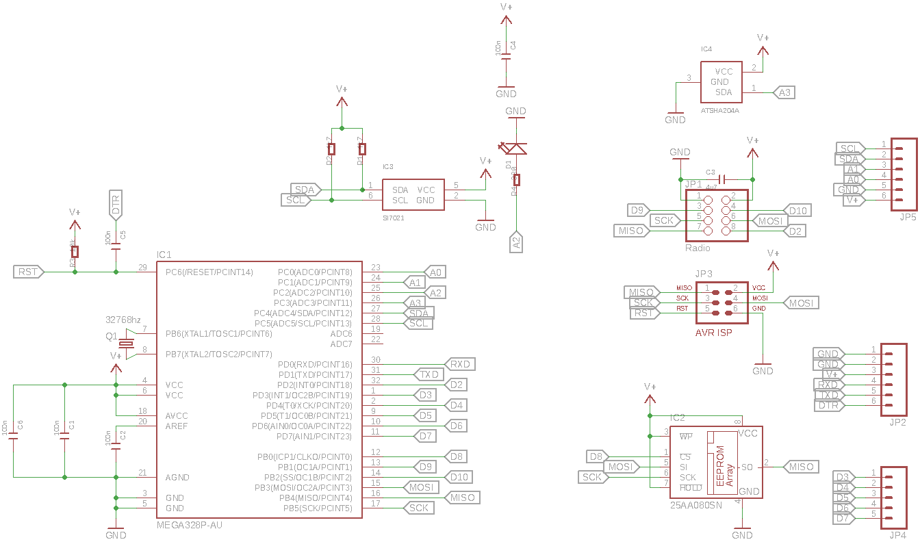
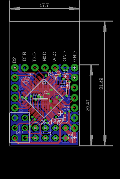
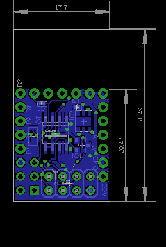
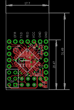
    It's single wire atsha204, it's connected to A3. I couldn't fit in the 8 pin variants of the atsha204, so that ruled out the full I2C bus version. It even took me a couple of hours of re-routing to make enough room for the sot23 housing of the ATSHA204.

    Anyway, schematic / pcb layouts are as follows

    MySensorV2-schematic.png
    MySensorV2-full.png MySensorV2-bottom.png MySensorV2-top.png


  • Contest Winner

    @tbowmo Excellent.


  • Hero Member

    @tbowmo Once again,... Well Done!


  • Admin

    And for the fun of it.. Just made a github repository of the design

    https://github.com/tbowmo/MySensorMicro

    Just in case anyone would like to have a closer look in eagle.


  • Hero Member

    I wonder what kind of "hit" on battery life authentication/encryption will have?


  • Contest Winner

    I do not think it is a big issue. Authentication is normally only needed on nodes that have actuators. And this implies that they always have to listen for incoming data and are therefore inherently non-battery friendly The ATSHA has a very low power consumption, so the added cost for message signing procedures is probably negligible compared to the cost of running the radio continuously.


  • Admin

    Hmm thinking about it, authentication could be valuable on sensors as well.

    If you use the sensor readings to control another actuator, then an attacker could send in his own bogus sensor values in order to trigger system events. He does need to know the specifics about your setup though, so the question is if it's affordable to the mischief to do anything like that πŸ™‚


  • Contest Winner

    Yep. This is true, and something I eventually have to add support for.


  • Admin

    @tbowmo said:

    @Dirk_H said:

    @tbowmo I don't see a Load Capacitor on the crystal. Especially if you need a precise clock you should use some. Have a look at https://www.adafruit.com/blog/2012/01/24/choosing-the-right-crystal-and-caps-for-your-design/ for example about Load Capacitors.

    I know that normally the crystal require load capacitors, but for the low freq. oscilator (32Khz) its not necessary (as far as I have read), that's why I omitted them from the design. I'll try and dig out the datasheets when I'm at home and double check things.

    Got around to check up on datasheet for atmel328p, when using lowfrequency oscilator, it has internal load capacitors. If you look at page 33 in the datasheet. So it's not necessary for external capacitors


  • Admin

    very soon the next prototype pcb revision will be ordered from China. Gonna be exciting. Almost like Christmas, where the kids just wanna open their gifts πŸ™‚


  • Admin

    And pcb's are ordered.. Again, using dirtypcbs.com, for the order..

    I have used a panelizer tool from http://blog.thisisnotrocketscience.nl/ to panelize the boards this time, so it should be easier to depanelize it when they get here..

    0f7e7ea77da42f064aec6af94953d91b-4461_top.png


  • Hero Member

    @tbowmo Looks great!

    Haven't actually ordered anything produced by the panelizer yet, but the results look really amazing:

    panelizing2.jpg

    I was planning to finally get around to some boost regulators. But I need to design mine from scratch (these are just scavenged from other places) so they follow the same design guide lines and can be plugged in seamlessly to the main pcb.

    Would be great if there were some sort of common design to follow for designing shields and such.


  • Admin

    As you all probably have noticed, there is an mysensor logo on the boards, that I just ordered.. πŸ™‚

    I have been cooperating with @hek for a while, and this is going to be an "official Mysensor pcb" πŸ™‚

    We have been in discussions with a vendor in china, for doing SMT assembly as well.. We are currently waiting for the pcb's to arrive and get them populated, to verify that everything is as it should be, before we start up production in China.

    For a batch of 100 units, the price is about 13$ per unit, plus shipping/handling fee, this is without any profits to the project

    One question though, I made room for an ATSHA204 chip on the board, that could be used for authentication purposes, we want to know if this should be mounted as default on the board, as it will add arround 1$ to the unit price.

    Also how many would be interested in ordering one (or 10, 20, 50?) of them? πŸ™‚ (just so that we get an indication if we should make a batch of 100 units, or 500 units)


  • Hero Member

    @tbowmo

    That's 2 questions... πŸ™‚

    1. Yes, It's worth it to me (Hopefully there will be MySensors software support down the road)
    2. I would probably start off with 3 to 5.

    Will there be a "kit" price for those who want to populate and reflow themselves?


  • @tbowmo

    I would also be interested in at least 5 boards (initially) if they were populated, not ready for smt soldering yet.


  • Admin

    @ServiceXp said:

    @tbowmo

    That's 2 questions... πŸ™‚

    I edited it a couple of times while talking with @hek last evening, so it slipped. Hope you can forgive me πŸ˜‰

    1. Yes, It's worth it to me (Hopefully there will be MySensors software support down the road)
    2. I would probably start off with 3 to 5.

    Will there be a "kit" price for those who want to populate and reflow themselves?

    No kit version, the pcb will be released under oshw so you could order it yourself, and source the components. However my unit price for the initial units will hit 11-12$, so it's only 1 or 2$ extra to get it smt assembled in China.

    The more units we can order the cheaper it will become.


  • Hero Member

    @tbowmo I might be interested in a few, seeing as this PCB has some pretty unique features, but I'm still in the market for a board with an on-board regulator that will give me a bit more flexibility.

    The problem (for me) is that while waiting for any official hardware, I've bought a lot of other stuff. I had another 10x Arduino Pro Mini arrive just yesterday for instance. Plus the booster project above. I ordered a couple of hundred brand inductors and capacitors as well as ltc3525 ICs. So basically now I don't have a choice but to go it alone for the most part πŸ˜“

    What we could need right now is some clear direction, like whether the ATSHA204 is the way to go. Or some common form factor that would allow future shields or whatnot.

    Also, for something really small like this, to be put into production, I would have liked to have tried with the "smd / mini nrf24" version that is also available on Ebay, just to keep the size down even further. I just got three of those yesterday and they are indeed very tiny (pin header spacing is 1.27mm). Whether they work ok or not I do not know. I do know that some people on the forum have posted project pictures with these mini nrf24. I guess what I'm saying is that lowpowerlabs already invented the wheel here: http://lowpowerlab.com/moteino/
    Would be great to hang a mini nrf24 flat off of the back if at all possible. But given what we know of the nrf24 it would probably blow up in our faces compared to the RFM12B/RFM69 that the moteino uses. Of course, they also use a wire antenna while we still trust the pcb antenna ...


  • Admin

    @bjornhallberg said:

    @tbowmo I might be interested in a few, seeing as this PCB has some pretty unique features, but I'm still in the market for a board with an on-board regulator that will give me a bit more flexibility.

    The problem (for me) is that while waiting for any official hardware, I've bought a lot of other stuff. I had another 10x Arduino Pro Mini arrive just yesterday for instance. Plus the booster project above. I ordered a couple of hundred brand inductors and capacitors as well as ltc3525 ICs. So basically now I don't have a choice but to go it alone for the most part πŸ˜“

    What we could need right now is some clear direction, like whether the ATSHA204 is the way to go. Or some common form factor that would allow future shields or whatnot.

    Also, for something really small like this, to be put into production, I would have liked to have tried with the "smd / mini nrf24" version that is also available on Ebay, just to keep the size down even further. I just got three of those yesterday and they are indeed very tiny (pin header spacing is 1.27mm). Whether they work ok or not I do not know. I do know that some people on the forum have posted project pictures with these mini nrf24. I guess what I'm saying is that lowpowerlabs already invented the wheel here: http://lowpowerlab.com/moteino/
    Would be great to hang a mini nrf24 flat off of the back if at all possible. But given what we know of the nrf24 it would probably blow up in our faces compared to the RFM12B/RFM69 that the moteino uses. Of course, they also use a wire antenna while we still trust the pcb antenna ...

    I forgot about the mini nrf24 modules. But I don't think that we could have squeezed it that much more in size, we could probably save 2-3mm in stack height, but that's about it.

    Also, this board was designed from the beginning to be a battery operated node. That is why there is no regulator on board (besides the fact that there is no room for it). I selected the components for their ability to work on low voltages all, except the atsha204, is able to work on a VCC as low as 1.8V)

    I have seen lot's of questions asking about battery operation of 3.3V arduino mini pro, with DHT22 sensors attached. People cut LED's and regulators on the arduino, in order to get the power consumption as low as possible. This is where this particular board fits in. It's ready for battery operation, and has the temperature / humidity sensor build in.

    It started out because I wanted an "easy" clean option for sensor nodes for my own application, without any wire nests between arduino and nrf24 modules. I hope that it will be useful for others as well, and might be able to get others going with the mysensor project.

    For my own part, I could use up to 20 of these, for measuring temperature / humidity in every room in the house (and out side as well)

    Btw. all those arduinos you've bought, could be turned into something else πŸ™‚


  • Hero Member

    I snapped some pictures just so everyone can see the difference between the nrf24 modules.
    _MG_3962.jpg
    _MG_3963.jpg
    Of course, like I said, I don't even know if the "mini" works in a satisfactory manner. I'm gonna get some smaller pitch headers so I can make a prototype. But the PCB antenna actually seems to be the exact same size so I have high hopes for that aspect at least.


  • Admin

    @bjornhallberg

    The antenna still needs to hang over "free air" (or an unrouted PCB area), this is the area where the logo is located on the current design. It could be moved to the opposite end of the pcb (where the nrf24 pinheader is located).

    If we switch to the mini module, then the pinheader for the radio is removed, but then you need a "larger" area where there is no components at all, in order to mount the nrf module flat to the sensor pcb. So in theory it will not be that much smaller, only the pinheader distance between the two pcbs can be removed.. lenght /width will be almost the same, maybe a bit longer as there is not that much room to give, with the current number of components (Si7021, eeprom, atsha204 etc).


  • Hero Member

    @tbowmo Yeah, you're probably right. It would take some re-design and you might not save all that much space, given all the other components as you say.

    Still, it'd be great to achieve something ... flatter ... like:
    http://harizanov.com/2014/07/diy-internet-of-things-fire-alarm/
    Runs an attiny84 though, but still.


  • Admin

    @bjornhallberg

    Could you measure the mini pcb? the width of the module, and lenght of the area with gnd, and the length of the antenna area (and total length of the module, should be the two lengths added together)


  • Hero Member

    @tbowmo I found an old post I made here:
    http://forum.mysensors.org/topic/413/is-there-a-schematic-of-the-nrf24-board/2
    I checked the measurements and they seem right. In addition, the antenna-area is about 8mm long.


  • Admin

    @bjornhallberg

    made a mockup of the nrf24 mini module, and tried to place it on the sensor board.. If I should use it, I have to remove the ISP pinheader from the board, as there is no room for it.

    Also, it is filling up almost half the populated pcb area on the sensor board, which means that there is not enough space for the components, and we have to make a bigger pcb, in order to have room for everything.


  • Hero Member

    @tbowmo Yeah, better to save it for a future project. I mean, there will never be a one size fits all and that is what is so great about MySensors. All the PCBs designed so far have a purpose and a market. And ideally, we'd want a few of each in the sensor network to complement each other.

    The reason I brought up the "mini", aside from wanting a flatter sensor node, is that the module seems to be getting more common on Ebay as well as cheaper. I've seen some sellers that sell them for the same price as the regular NRF24 now (in 10pcs). Four months ago, they were rare and many times more expensive. So if they work as advertised they could soon replace the NRF24 module we've all come to use.

    In this context, and knowing very little of antennas, it is too bad they don't have a version without the PCB antenna altogether. We could add our own antennas and more easily fit the module on miniscule sensor nodes such as yours.


  • I would be interested in 5 units. I lean towards including ATSHA204 and smt assembled, but I would buy without and unassembled.


  • Admin

    @tlund

    So you would just buy the PCB, and source all components yourself?


  • @tbowmo
    Sorry I was a bit unclear. I would like to buy all components as a package from you/mysensors. Preferably assembled, but I would also accept if you sell it unassembled (pcb+components). I would rather not have to source the components myself πŸ™‚

    Btw, have you measured the actual power consumption? Sleep vs temp/hum measurement?


  • Admin

    @tlund

    I haven't measured supply current, as I don't have the equipment to do that. I am looking at getting the uCurrent gold from eevblog, but it's expensive to import it to Denmark.

    It will probably not be offered as a kit. Too much work from my/our part πŸ™‚


  • Admin

    @tbowmo said:

    uCurrent gold

    I can probably test it using mine. Any plans going to SkΓ₯ne soon πŸ˜‰


  • Hello, I'd be in for at least 5 assembled boards.


  • Soo .. this like a breadmix ? πŸ™‚ All we have to add is the sensors ?


  • Admin

    @hek

    You already got an ucurrent? I had planned to import an extra one from Australia for you πŸ™‚ (thought that we might be able to save some $ if we ordered 4-5 units).

    But as so many other things i got away from it again 😞

    Unfortunately I only come to Copenhagen these days, visiting a client.


  • Admin

    @JimmyH

    There is a temperature / humidity sensor on it already. But more can be added πŸ™‚


  • Admin

    Ok, pushed a product page to the main site just now. Hope the page is selling enough. πŸ˜‰

    http://www.mysensors.org/hardware/micro


  • Hero Member

    "ATSHA204A sot23 footprint on board"

    So does that mean this run will not have the ATSHA204A populated?


  • Admin

    @ServiceXp

    We haven't started production yet, I'm still waiting for the latest prototype pcb to arrive from China, before I can make the (hopefully) last prototype before "mass production". Which also means I have to find the atsha204 somewhere, so I can test it.

    And yes I know mouser has it, but I don't need that much more from them, so will have to pay a big handling/shipping fee to them


  • Admin

    @Anticimex , did you have any spare atsha204 left?


  • Hero Member

    @tbowmo Have you looked on AliExpress. A quick search seems to suggest that could be a viable alternative. Try some different search combinations though ... their search engine sucks. "ATSHA204" wont find "ATSHA204A" for instance when I try.

    Wont be quick though, and the Chinese New Year is coming up ...


  • Contest Winner

    I can part with a SOT23 ATSHA204A if necessary. They can also be sampled from Atmel in small quantities for free (that's what I did).


  • Admin

    @Anticimex said:

    sampled

    Do you remember the deliver time on samples?


  • Contest Winner

    @hek It took three days from order confirmation to shipment notification. I don't recall the transit times but it went out with DHL WW Express so it should be pretty fast. Say 5-10 working days tops.


  • Admin

    @Anticimex said:

    @hek It took three days from order confirmation to shipment notification. I don't recall the transit times but it went out with DHL WW Express so it should be pretty fast. Say 5-10 working days

    hmm what is the sample quantity limit?


Log in to reply
 

Suggested Topics

  • 87
  • 3
  • 6
  • 5
  • 2
  • 10

0
Online

11.2k
Users

11.1k
Topics

112.5k
Posts