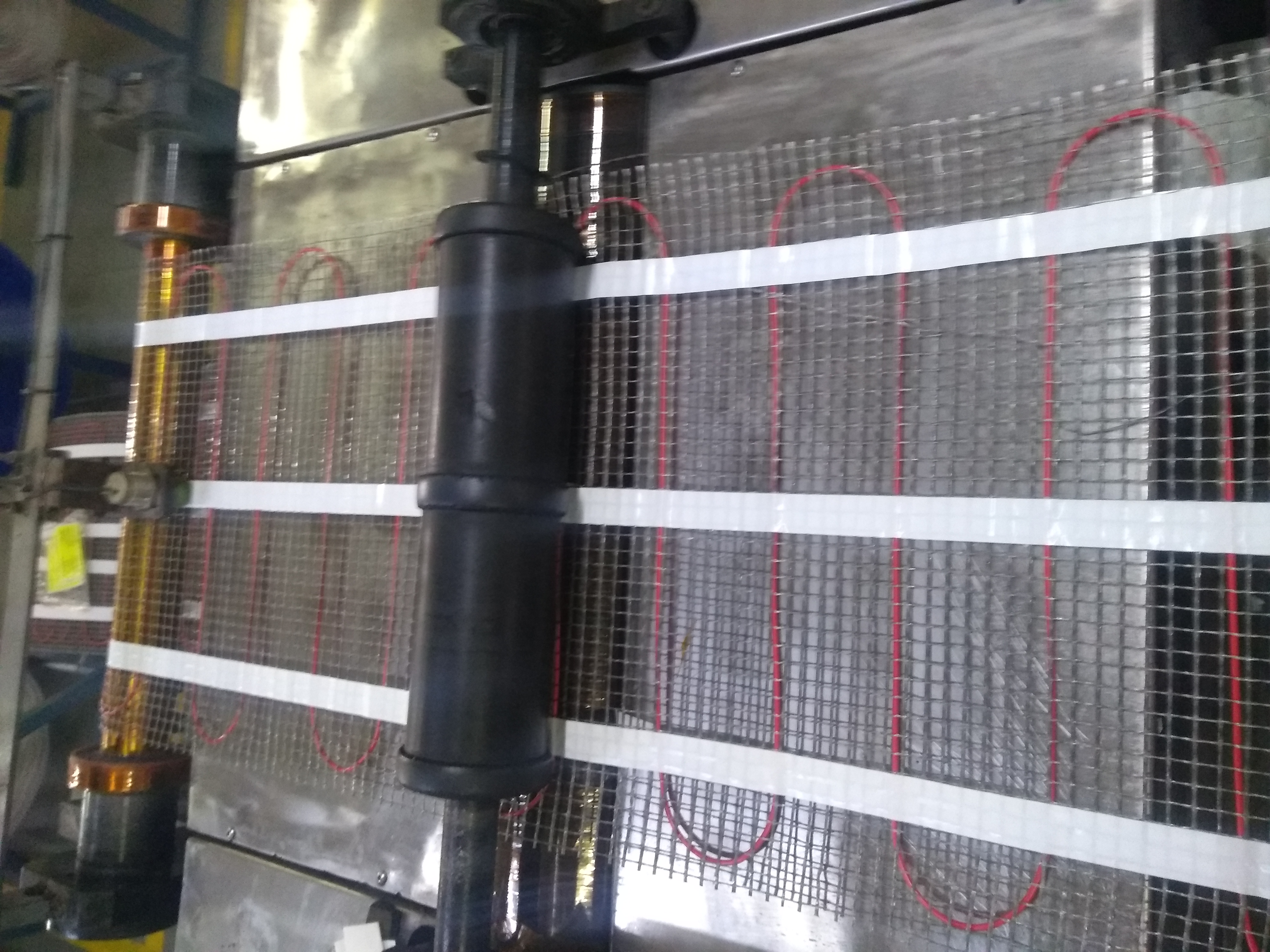
Sensor required to detect PVC insulated COPPER wire
-
Or create a metal detector, that will detect every copper wire that passes below the sensor.
What is important is to ensure a good reliability, so you are getting results that is reliable. Both IR detector and metal detector should be usable for youhttps://circuitdigest.com/microcontroller-projects/arduino-metal-detector-circuit-code/
https://www.allaboutcircuits.com/projects/metal-detector-with-arduino/ -
If the copper loop is continuous (it looks like it is), inject a small RF (mW) signal on the wire (at the feed end of the mesh) and place the complement detector under the final end.
-
@kimot thanks for the reply. Yes we have tried with 30mm sensing range inductive proximity sensor... It's not working on copper.
@yemesvee
Then another approach you can count rotations on one of the drums, add a magnet to the drum, and use a reed relay as sensor.
then you have to manually calibrate, measure pulses until you have reach 1 loop.
then re-check count pulses until you have reached 10 loops. just to ensure you have measured correctly.you can use this sketch as a start
https://www.mysensors.org/build/binary -
If the mesh moves at constant speed, How about a simple optical IR Sensor (break beam or Reflective), then checking pulse width of signal to detect mesh vs cable. Otherwise synchronize pulse width detection ratio in correlation to mesh speed.
Similar to this

@hard-shovel Thanks for the reply. The Ir sensor will detect both mesh and copper wire. How to count the no. of copper wire loops?? I don't understand..Can you please elaborate...
-
@yemesvee
Then another approach you can count rotations on one of the drums, add a magnet to the drum, and use a reed relay as sensor.
then you have to manually calibrate, measure pulses until you have reach 1 loop.
then re-check count pulses until you have reached 10 loops. just to ensure you have measured correctly.you can use this sketch as a start
https://www.mysensors.org/build/binary -
Color sensor?
-
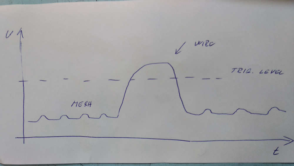
But I still think, that using opto detection will be easy possible.
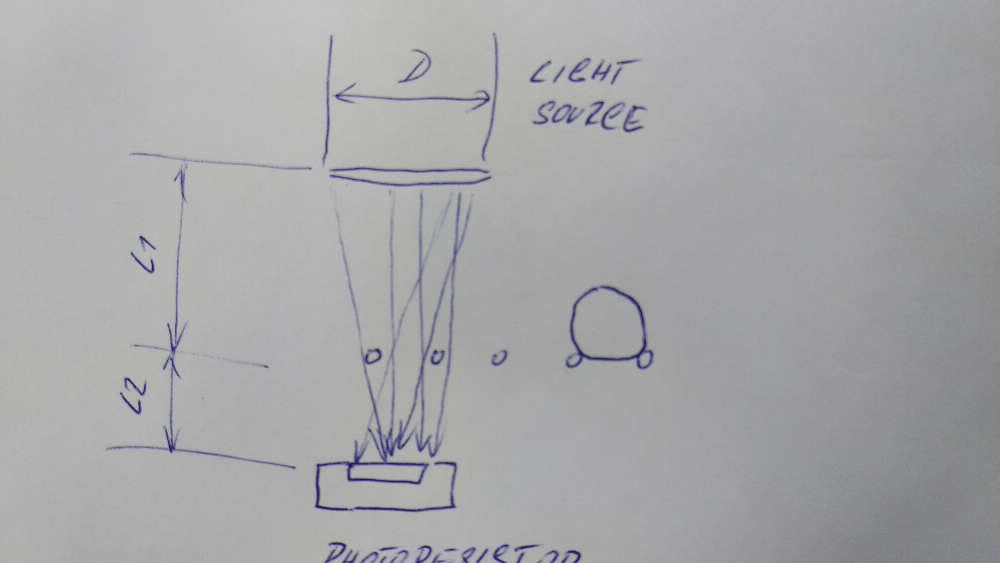
For example photo resistor has got large area for receiving light and mesh will not cover it completely.
But wire almost does.
So signal level from photoresistor differ for mesh and wire and you can measure it by software or set analog comparator trigger level.Experimet with D, L1 and L2
https://en.wikipedia.org/wiki/Photoresistor
-
@hard-shovel Thanks for the reply. The Ir sensor will detect both mesh and copper wire. How to count the no. of copper wire loops?? I don't understand..Can you please elaborate...
@yemesvee
If using a digital sensor mounted as per Kimot diagram you will receive a pulse stream, check the width of the pulsed to find if mesh or cable.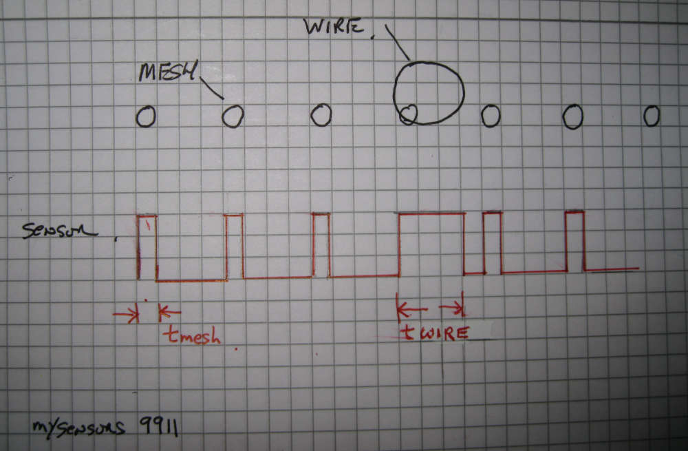
use the function pulseIn to determine the pulse width.
The simple example of the time duration of a pulse int SensorPin = 3; unsigned long duration = 0; unsigned long CableDuration = 100; // Set to suitable value unsigned long CableCount = 0; void setup() { pinMode(SensorPin , INPUT); } void loop() { duration = pulseIn(SensorPin , HIGH); Serial.print("Duration : "); Serial.println(duration); if (duration >= CableDuration) { ++ CableCount; Serial.print("Cable detection :"); Serial.println(CableCount); } } -
@yemesvee
If using a digital sensor mounted as per Kimot diagram you will receive a pulse stream, check the width of the pulsed to find if mesh or cable.use the function pulseIn to determine the pulse width.
The simple example of the time duration of a pulse int SensorPin = 3; unsigned long duration = 0; unsigned long CableDuration = 100; // Set to suitable value unsigned long CableCount = 0; void setup() { pinMode(SensorPin , INPUT); } void loop() { duration = pulseIn(SensorPin , HIGH); Serial.print("Duration : "); Serial.println(duration); if (duration >= CableDuration) { ++ CableCount; Serial.print("Cable detection :"); Serial.println(CableCount); } }@hard-shovel
But mesh is on other direction too - parallel with movement and sure not still at the same position and pure parallel.
So digital signal can be generated longer time than you expected.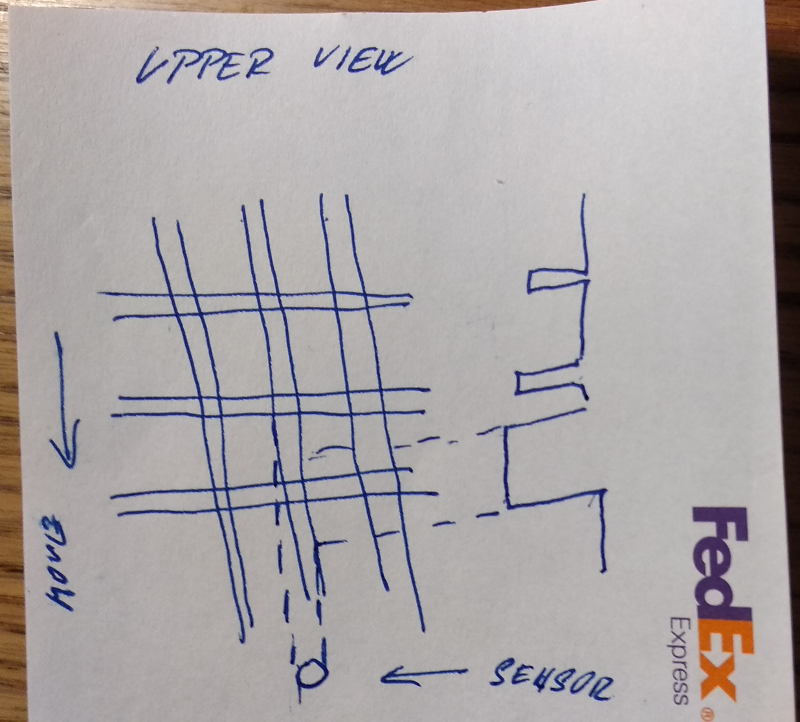
Hello! It looks like you're interested in this conversation, but you don't have an account yet.
Getting fed up of having to scroll through the same posts each visit? When you register for an account, you'll always come back to exactly where you were before, and choose to be notified of new replies (either via email, or push notification). You'll also be able to save bookmarks and upvote posts to show your appreciation to other community members.
With your input, this post could be even better 💗
Register Login