What did you build today (Pictures) ?

-
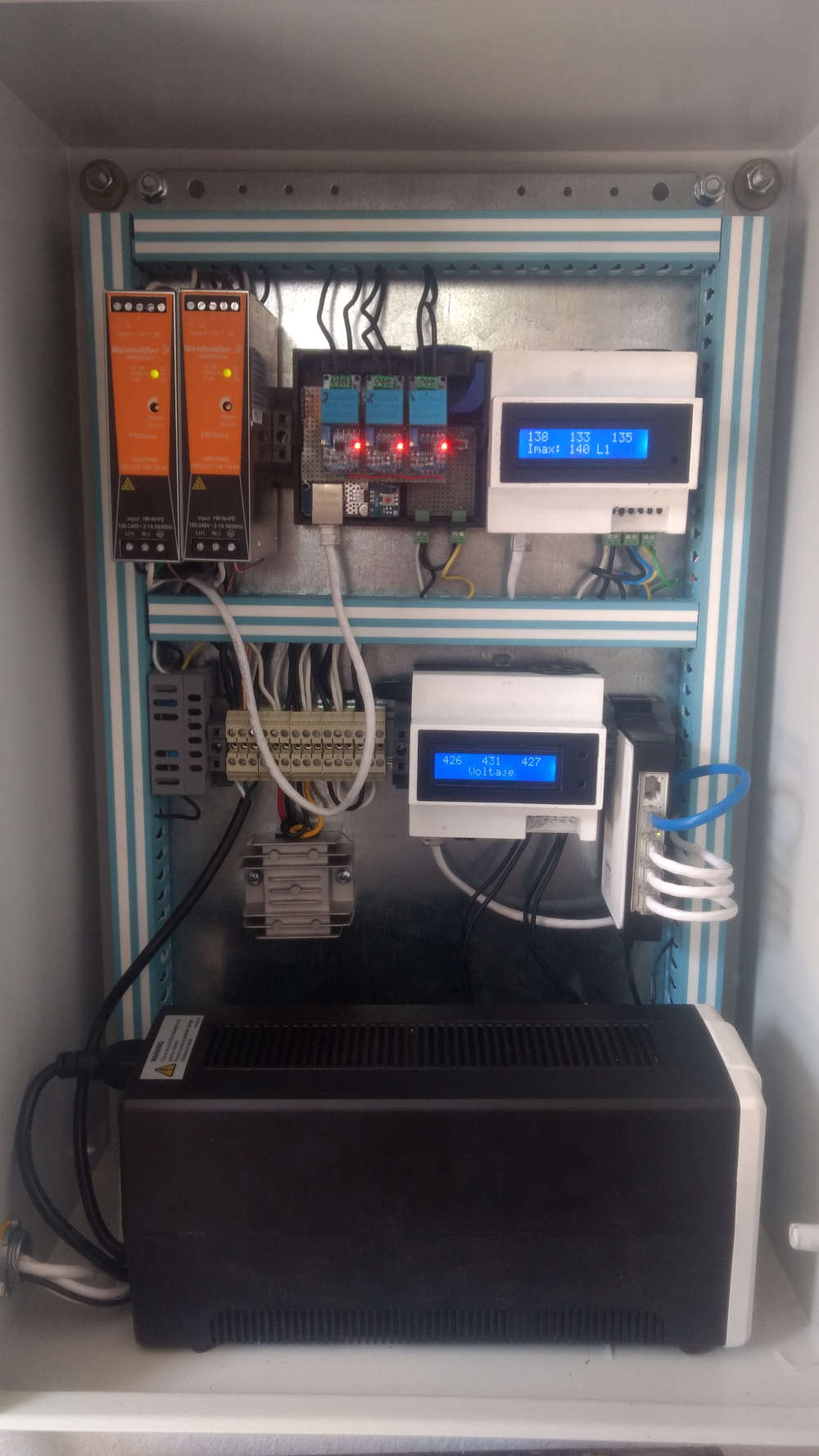
well this is my project , right now im using 2 arduino nano with ethernet shield to read 3 lines Voltage on a delta instalation , 3 current sensors of 300amps for a motor , and 1 water pressure ,
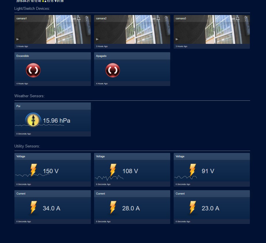
all conected to a raspberry pi with domoticz
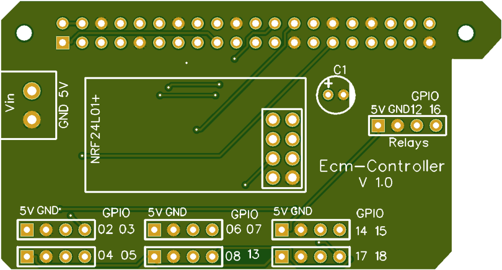
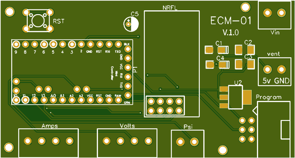
but yesterday i decide to change all , instead of 2 uno i will use a pro mini with a nrf24
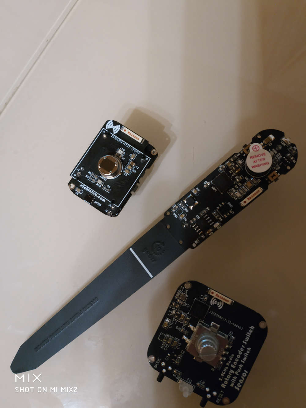
so i desing two pcb
some code
#define MY_NODE_ID 100
#define MY_DEBUG
#define MY_RADIO_NRF24

#include <SPI.h>
#include <MySensors.h>


#define CHILD_ID_VOLT_1 1
#define CHILD_ID_VOLT_2 2
#define CHILD_ID_VOLT_3 3

#define CHILD_ID_CURRENT_1 4
#define CHILD_ID_CURRENT_2 5
#define CHILD_ID_CURRENT_3 6

#define CHILD_ID_PRESION 7

#define VOLT_SENSOR_ANALOG_PIN_1 0
#define VOLT_SENSOR_ANALOG_PIN_2 1
#define VOLT_SENSOR_ANALOG_PIN_3 2

#define CURRENT_SENSOR_ANALOG_PIN_1 3
#define CURRENT_SENSOR_ANALOG_PIN_2 4
#define CURRENT_SENSOR_ANALOG_PIN_3 5


#define PressPin      A6


unsigned long SLEEP_TIME = 20000; // Sleep time between reads (in milliseconds)

MyMessage msg(CHILD_ID_VOLT_1, V_VOLTAGE);
MyMessage msg2(CHILD_ID_VOLT_2, V_VOLTAGE);
MyMessage msg3(CHILD_ID_VOLT_3, V_VOLTAGE);

MyMessage msg4(CHILD_ID_CURRENT_1, V_CURRENT);
MyMessage msg5(CHILD_ID_CURRENT_2, V_CURRENT);
MyMessage msg6(CHILD_ID_CURRENT_3, V_CURRENT);

MyMessage pressureMsg(CHILD_ID_PRESION, V_PRESSURE);

float lastVolt1;
float lastVolt2;
float lastVolt3;

float lastCurrent1;
float lastCurrent2;
float lastCurrent3;

float lastPresion;


int pressure = 0;
float PSI = 0;
float PSI_CAL = 2.0;            // Calibration of sensor
int PSImsb = 0;
int PSIr = 0;


void before() {

}


void presentation()
{
 sendSketchInfo("Multisensor", "1.7");  // Send the sketch version information to the gateway and Controller
 present(CHILD_ID_VOLT_1, S_MULTIMETER);   // Register this device as power sensor
 present(CHILD_ID_VOLT_2, S_MULTIMETER);   // Register this device as power sensor
 present(CHILD_ID_VOLT_3, S_MULTIMETER);   // Register this device as power sensor

 present(CHILD_ID_CURRENT_1, S_MULTIMETER);   // Register this device as power sensor
 present(CHILD_ID_CURRENT_2, S_MULTIMETER);   // Register this device as power sensor
 present(CHILD_ID_CURRENT_3, S_MULTIMETER);   // Register this device as power sensor

 present(CHILD_ID_PRESION, S_WATER);   // Register this device as power sensor

}


void setup()
{

}

void loop()
{
 int Voltaje1 = analogRead(A0);
 int Voltaje2 = analogRead(A1);
 int Voltaje3 = analogRead(A2);

 int Corriente1 = analogRead(A3);
 int Corriente2 = analogRead(A4);
 int Corriente3 = analogRead(A5);


 float VoltLevel1 = map(Voltaje1,0,1023,0,500);
 float VoltLevel2 = map(Voltaje2,0,1023,0,500);
 float VoltLevel3 = map(Voltaje3,0,1023,0,500);

 float CorrienteLevel1 = map(Corriente1,0,1023,0,200);
 float CorrienteLevel2 = map(Corriente2,0,1023,0,200);
 float CorrienteLevel3 = map(Corriente3,0,1023,0,200);


 Serial.print("Voltaje L1: ");
 Serial.println(VoltLevel1);
 Serial.print("Voltaje L2: ");
 Serial.println(VoltLevel2);
 Serial.print("Voltaje L3: ");
 Serial.println(VoltLevel3);


 Serial.print("Corriente L1: ");
 Serial.println(CorrienteLevel1);
 Serial.print("Corriente L2: ");
 Serial.println(CorrienteLevel2);
 Serial.print("Corriente L3: ");
 Serial.println(CorrienteLevel3);

 //sensor de voltaje
 if (VoltLevel1 != lastVolt1) {
     send(msg.set(VoltLevel1, 1));
     lastVolt1 = VoltLevel1;
 }

   if (VoltLevel2 != lastVolt2) {
     send(msg2.set(VoltLevel2, 1));
     lastVolt2 = VoltLevel2;
 }
   if (VoltLevel3 != lastVolt3) {
     send(msg3.set(VoltLevel3, 1));
     lastVolt3 = VoltLevel3;
 }


//sensor de corriente
   if (CorrienteLevel1 != lastCurrent1) {
     send(msg4.set(CorrienteLevel1, 1));
     lastCurrent1 = CorrienteLevel1;
 }
     if (CorrienteLevel2 != lastCurrent2) {
     send(msg5.set(CorrienteLevel2, 1));
     lastCurrent2 = CorrienteLevel2;
 }
     if (CorrienteLevel3 != lastCurrent3) {
     send(msg6.set(CorrienteLevel3, 1));
     lastCurrent3 = CorrienteLevel3;
 }

/* ************************************************ */
   pressure  = analogRead    (PressPin) ;        // junk read
   wait(25);

/* • Output: 0.5V – 4.5V linear voltage output. 0 psi outputs 0.5V, 50 psi outputs 2.5V, 100 psi outputs 4.5V
   0   psi = .33v after scalling 5.0v to 3.3v
   50  psi = 1.65v
   100 psi = 2.97v

   3.3v/1024 = .0032266 volt per bit
*/
   pressure  = analogRead    (PressPin) ;

   if (pressure < 106) pressure = 106;         // this is minimum of .5v
   PSI = (pressure - 106 ) * .1246;            // where did we get this?? was .119904
   PSI = PSI + PSI_CAL;                        // adjustment

   PSImsb = PSI * 100;
   PSIr = PSImsb % 100;


   send(pressureMsg.set(PSI, 2));            // Send water pressure to gateway

   Serial.print("Presion: ");
   Serial.println(PSI);

   wait(200);

    // end of if (SLEEP_MODE || (cu


 sleep(SLEEP_TIME);
}
havent tested with sensors yet
but looks good so far
-
@berkseo whoa, time for a Kickstarter! They look great! Where did you have them made, and what do they cost?
@fernando-alvarez-buylla Always nice to see the Aurora theme being used :-)
-
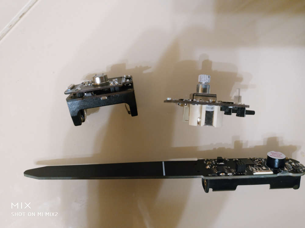
And a few days later my pcb's arrived
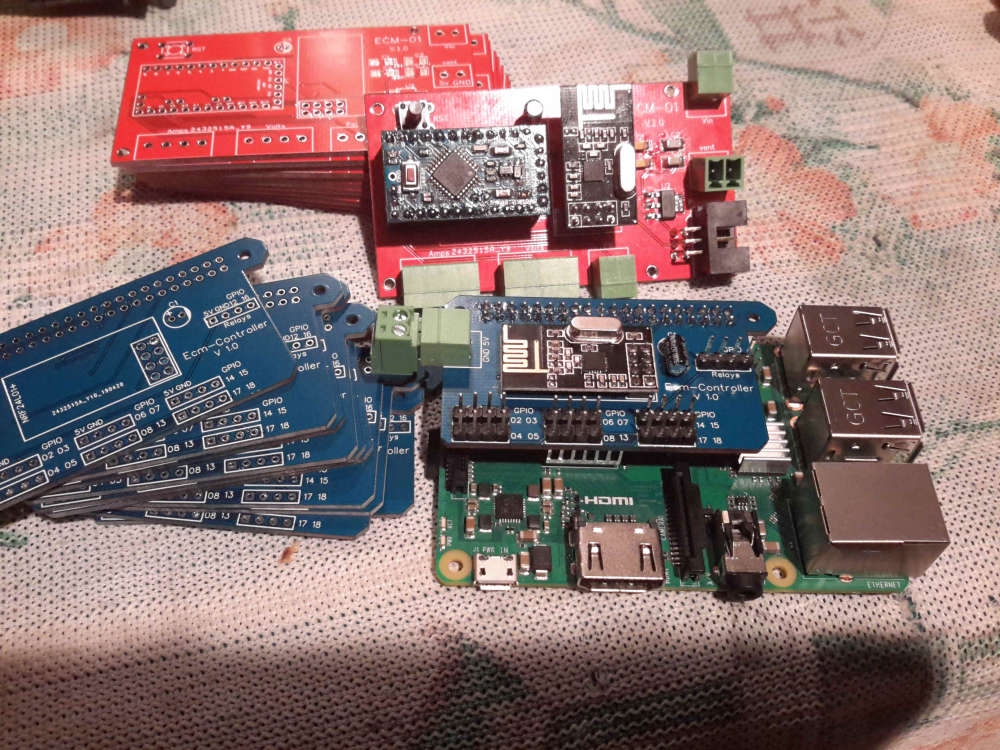
Now to test the next version
-
-
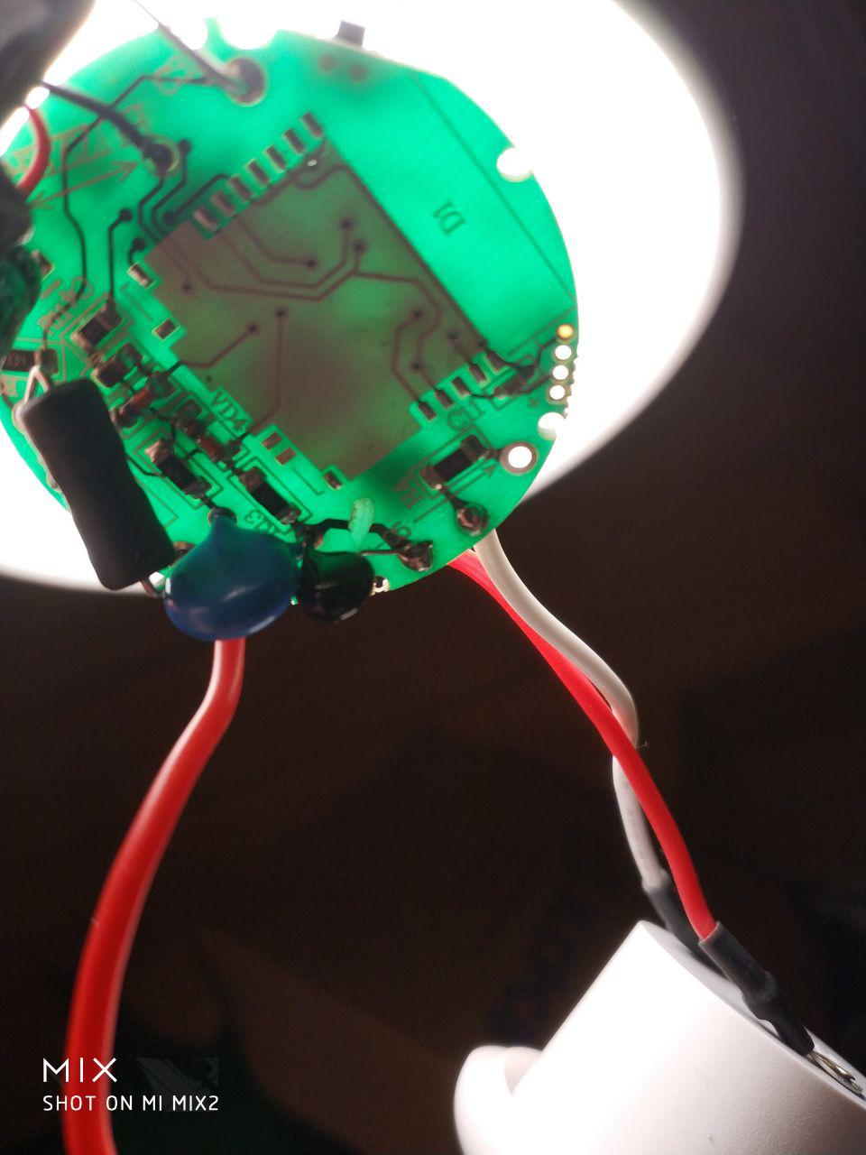
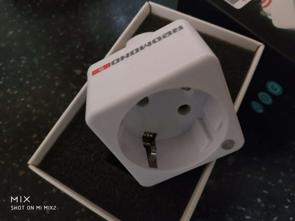
@berkseo very cool! How did you do that? Did you just have to connect the serial holes to an ST_LINK adapter or something similar? Was is difficult to open the device? And, most importantly: is your code available somewhere?
-
-
@berkseo whoa, time for a Kickstarter! They look great! Where did you have them made, and what do they cost?
@fernando-alvarez-buylla Always nice to see the Aurora theme being used :-)
-
@berkseo very cool! How did you do that? Did you just have to connect the serial holes to an ST_LINK adapter or something similar? Was is difficult to open the device? And, most importantly: is your code available somewhere?
-
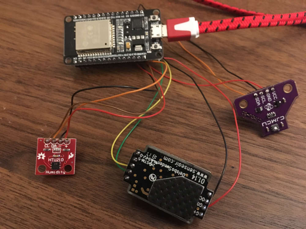
Added two other (e)co2 sensors to my test-setup.
Now 3 NDIR and 2 VOC under observation. :)
-
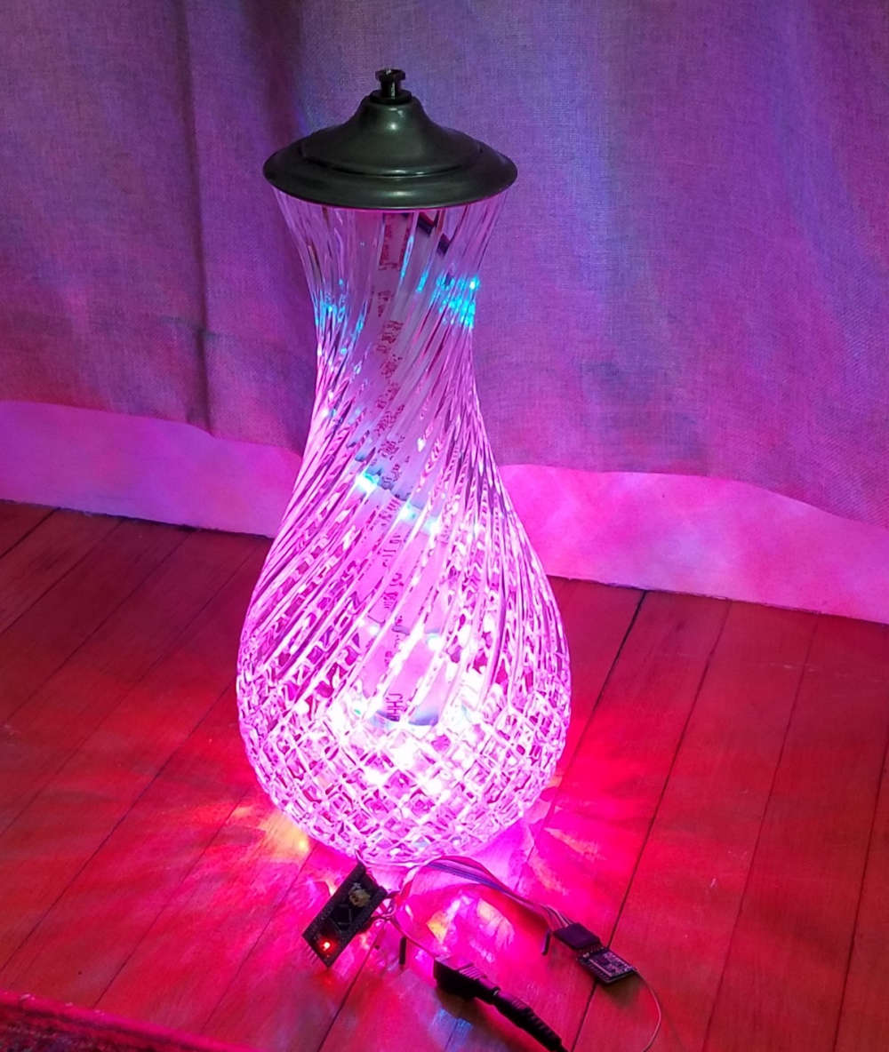
A family member gave me an old lamp with a fancy glass base. Well, I didn't like the lamp, but the base was nice, so I kept it in my basement for a few years. I found it again the other day and decided it needed to become a new type of lamp. I put a 150 LED strip (WS2812B) inside. I have an STM32 Blue Bill and RFM69HCW to run the light patterns and connect to MySensors.
In Domoticz, I have it set up as a dimmer light, but the node just switches patterns depending on what the dimmer level is.
At first, I wrapped the LED strip carefully around a tube that sits in the center of the glass jar, but it didn't look very good. Somehow just spiraling the strip in the bottom of the lamp has a much better effect.
My wife even liked it, so maybe I will put some finishing touches on it and actually use it as a lamp : )
-
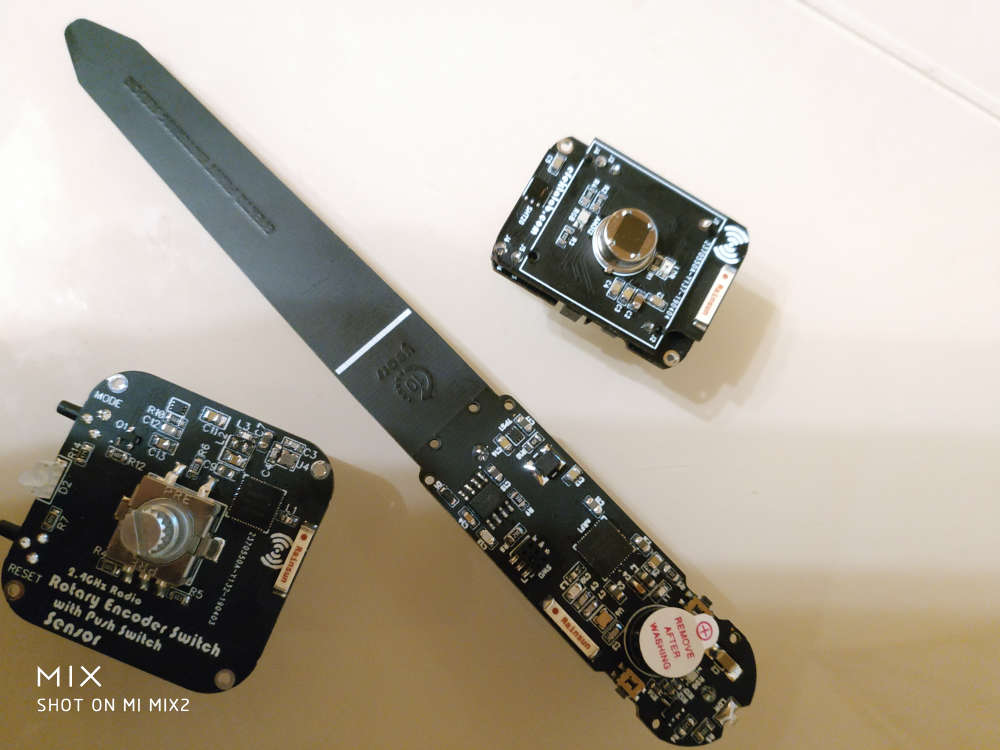
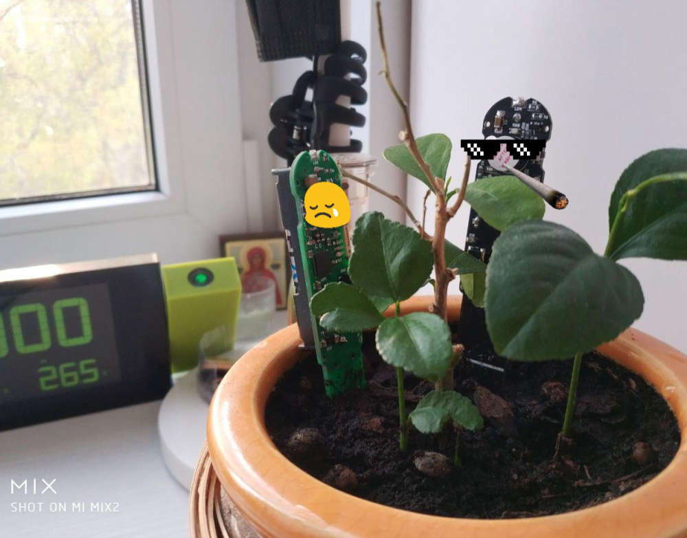
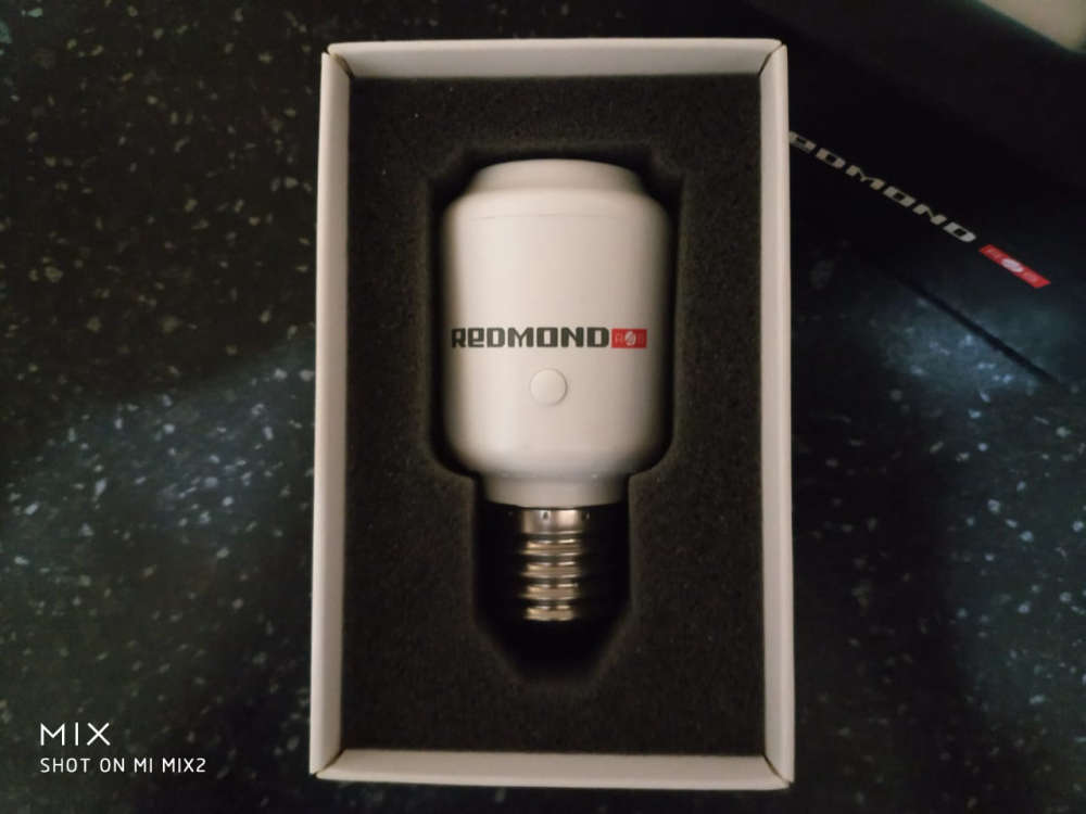
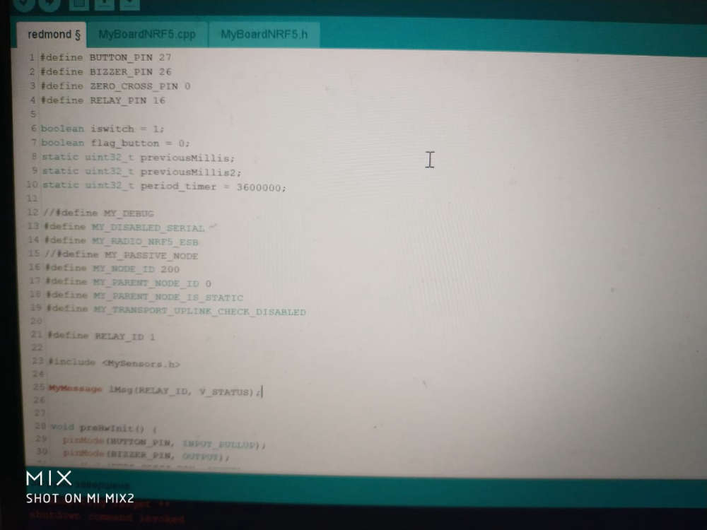
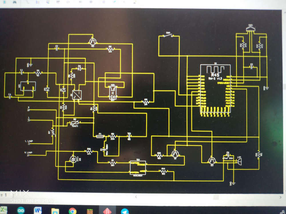
@alowhum Soon I will publish codes and the description of process of dismantling and a firmware. But getting ahead.. it's very simple :)
@berkseo
https://translate.google.ru/translate?hl=&sl=ru&tl=en&u=https%3A%2F%2Fmysku.ru%2Fblog%2Fdiy%2F72557.htmlOriginal (code without Google formatting): https://mysku.ru/blog/diy/72557.html
-
Test nRF52840 with Mysensors on Arduino IDE
https://youtu.be/dLXDBjsmVhEbased on source - https://translate.google.ru/translate?sl=ru&tl=en&u=https%3A%2F%2Fmysensors-rus.github.io%2Fnrf52840-The-first-steps%2F
-
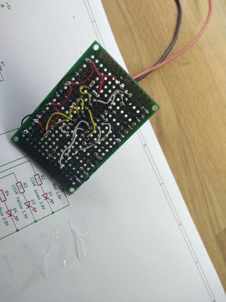
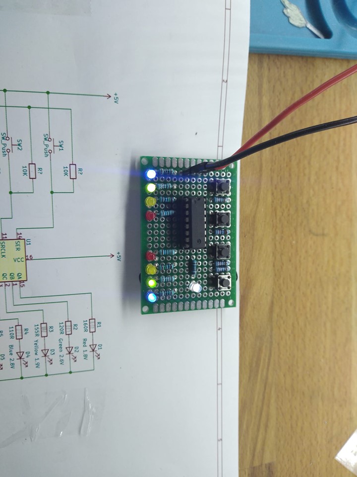
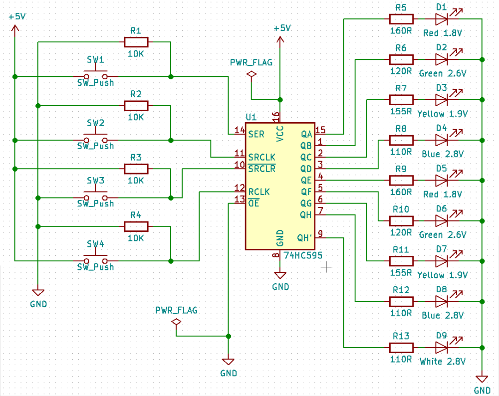
Well, Design of an home made electronic kit for my 10yo daughter to teach her by example. on 74HC595 (shift reg), 9 leds, 4 push buttons, some wrapping wire, ... We managed to build it, it works, with some bad contacts, but it works, she enjoyed the thing and the time spent together. Here is the schema and the pictures. I strongly invite parents to build it with their children, easy and fun. !
-
Well, Design of an home made electronic kit for my 10yo daughter to teach her by example. on 74HC595 (shift reg), 9 leds, 4 push buttons, some wrapping wire, ... We managed to build it, it works, with some bad contacts, but it works, she enjoyed the thing and the time spent together. Here is the schema and the pictures. I strongly invite parents to build it with their children, easy and fun. !
@fanfan
Looks nice, and I love the idea that you spend time and knowledge to your kids :-)
but looking at the current budget it seems that you are above the rated current consumption for the 74HC595, just so you don't wonder in case it burns when several LEDs are ON at the same timeInput clamp current, I IK (V I < 0 or V I > V CC ) ±20 mA
Output clamp current, I OK (V O < 0 or V O > V CC ) ±20 mA
Continuous output current, I O (V O = 0 to V CC ) ±35 mA
Continuous current through V CC or GND ±70 mAData from here:
https://www.sparkfun.com/datasheets/IC/SN74HC595.pdf -
@alowhum Soon I will publish codes and the description of process of dismantling and a firmware. But getting ahead.. it's very simple :)
-
@sincze I should have known. All you had to say was memory and it would have made sense, or should I say sincze. LOL. With needing to hold states of 900 LEDs, I am going to guess that they are WS2812 LED strips.
@dbemowsk I've been gambling with an Adafruit AudioFX board and cobbled together this annunciator. Eventually it will likely be a MySensors node to play alarms or different sounds. It is using a reasonably-priced transportable speaker to play the sounds. I were given it to work with my doorbell button node today.
-
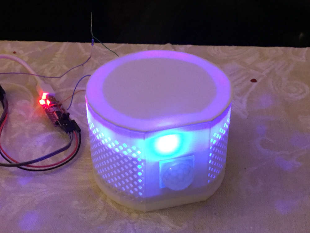
Prototyping my netatmo replacement device. It has an led strip that can simulate a lighouse, a rainbow or a fireplace...
(If not used only for fun, it should warn you, if there is too much CO2 in the air.)
Hello! It looks like you're interested in this conversation, but you don't have an account yet.
Getting fed up of having to scroll through the same posts each visit? When you register for an account, you'll always come back to exactly where you were before, and choose to be notified of new replies (either via email, or push notification). You'll also be able to save bookmarks and upvote posts to show your appreciation to other community members.
With your input, this post could be even better 💗
Register Login