Cannot flash atmega328 on new custom board
-
Hello,
I've designed and made PCBs for a new custom board, one that can fit inside the space of a AA battery. However, I can't seem to flash it. Both the arduino IDE, and avrdude on its own can't talk to the board. avrdude either says the device initialization failed, or gives a random device signature. I've also tried two different programmers, a USBasp and an Arduino UNO as an ISP.I am trying to program to the board before adding the radio, as I realize the ISP and NRF radio share pins and would interfere with each other. The only components on the board at this stage are the ATMEGA328, C1, C2, R1 and the ISP header. The ATMEGA chips themselves are sourced from Arrow, and are brand new, however have been sitting on my shelf for a year or so. I wanted to check with the community before resorting to ordering fresh parts, as I'm not convinced the problem is in the chips themselves.
I've been over both the schematic and physical PCB with a fine tooth comb, and have come up stumped. I even built a 2nd board just to eliminate any issues with a single component, or my soldering work.
The schematic, and pictures of the finished board are below.
Excuse the potato photos. The chip does actually have writing on it. The soldering isn't amazing, but a continuity test shows its all making good connections to where it should go.Thanks.


Ninja edit: The output from avrdude

-
This below circuit is using a xtal and the 2 caps, it seems that you don't have those
https://www.arduino.cc/en/Tutorial/ArduinoToBreadboardalso it seems that you need to have a wire to AtMega 328 RESET pin connected from your programmer
See this link:
http://www.electronics-lab.com/burning-the-bootloader-on-atmega328-using-usbasp-programmer/ -
The crystal and caps are only needed if you are pulling an atmega from an arduino. By default, bare atmega's straight from the factory use an internal 8mhz oscillator, no crystal needed. And the reset line is connected, the schematic is just not that clear in that regard. the RESET label means its connected to the reset pin on the ISP header
-
Hi,
I did a comparable design before (Link) and might be able to give some hints.At first, I dont know if it is part of your current problem but your schematic lacks of a capacitor that "transforms" the DTR signal of the FTDI-programmer into your RESET signal for your ATMEGA.
See C3 in my schematic below.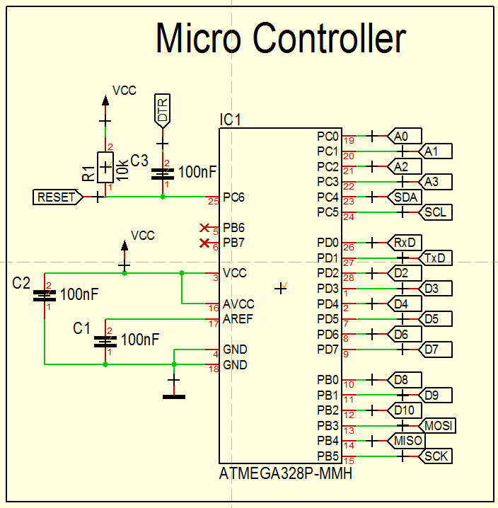
Instead you are routing the DTR-signal of the FTDI directly to the RESET pin which will not work.
Although I had my reset circuitry right, I also had some issues to program those boards at first.
The following approach worked fine for me:- Install "Sensebender Mirco" board definitions into Arduino IDE and select the 8MHz variant
- Connect USBasp programmer (with selected 3.3V supply if NRF24 is allready applied)
- Select USBasp as programmer and click on Burn Bootloader
- disconnect USBasp and install FTDI
- upload some sketch as usual
The last step might not work with your missing capacitor but maybe you can just tinker a bit with the cable that connects your FTDI to you board to insert this capacitor in your signal line.
By the way, if you FTDI programming is problematic but USBasb works fine, you can also use the USBasp directly to uplaod your scipt with the "upload with programmer" feature of the IDE.
And one last piece of experience: You wrote, that you have not soldered the NRF24 on the board so far to not interfere with the SPI lines for the ATMEGA flashing. According to my experience this was never an issue. I have my NRFs applied right from the start and I burned bootloaders and programmed the processor with the USBasp directly a hundret times and never had issues.
Regards,
Marco -
that's a while I reflashed a 328p so I have no direct idea,
still there are some points mentioned by others, or on your sch you could improve:- 100nf on Reset for DTR if you plan to use a bootloader
- decoupling.. I would have added 2-3 caps for 328p and the radio (better anticipate issues vs minimalistic board..)
- no pullups on SPI radio. In contrary of @marcoMD experience :) good to know it's not great practice for all cases. For more infos, https://hackaday.com/2014/11/25/better-spi-bus-design/
- in some cases, usbasp can output VCC3 but 5v on SPI line, https://www.hackster.io/billy-cheung/3-3v-usbasp-modification-c20557
- I guess you picked the right 328 part ref regarding your avrdude commandline settings ?
what happens when you apply your reprog procedure (usbasp or uno as isp) to a regular arduino board? Are you able to reprog them??
-
@AdamAnt Regarding the interference between MCU and the radio a pull-up resistor on the CSN line helps. By doing this you can program the MCU without any problems after soldering the radio module.
Now getting back to the main issue here:
- Did you checked for shorts between pins (especially the ICSP part: mosi, miso, sck and also the reset pin to not be shorted to ground keeping the mcu in a reset state). Asking this because I see some pins shifted over there a little bit on the corresponding pads from the PCB.
- Did you checked for continuity between the corresponding MCU pins and the ICSP header?
- Can you post some pictures on how did you wired the USBASP programmer and the ICSP header from the PCB?
The schematic seems fine from my point of view. There may be some problems due to faulty PCBs also from the factory (it happened to me) - that's why I suggested doing the above tests with a multimeter (shorts/continuity test).
-
that's a while I reflashed a 328p so I have no direct idea,
still there are some points mentioned by others, or on your sch you could improve:- 100nf on Reset for DTR if you plan to use a bootloader
- decoupling.. I would have added 2-3 caps for 328p and the radio (better anticipate issues vs minimalistic board..)
- no pullups on SPI radio. In contrary of @marcoMD experience :) good to know it's not great practice for all cases. For more infos, https://hackaday.com/2014/11/25/better-spi-bus-design/
- in some cases, usbasp can output VCC3 but 5v on SPI line, https://www.hackster.io/billy-cheung/3-3v-usbasp-modification-c20557
- I guess you picked the right 328 part ref regarding your avrdude commandline settings ?
what happens when you apply your reprog procedure (usbasp or uno as isp) to a regular arduino board? Are you able to reprog them??