d-diot: dual MySensors gateway for Raspberry... And more!
-
Impressive!
-
What does a fully realized board look like? Do you intend to sell them?
-
Hi alowhum, some pictures of the fully assembled board are here, while the list of components (BOM) is here.
My plan is to make also a demo video of the board in action, but, at the moment my problem is that I have a limited amount of free time (and I guess that this is true also for other people here), so... I don't know when it will be available.
For the same reason, a 3d-printable case (WAF is important :sweat_smile: ) is not yet available, but in (very) slow development.
Regarding the second question, yes, my idea is to produce (about 100?) and sell some boards through a Kickstarter campaign, if there is enough interest around.
In any case at the moment I have some unused pcb at home, so I can send two of them to the MySensors community or dev team for testing.
-
@tbowmo Very good question.
No for the moment the schematics is not available on the website because selling some boards is the only options that i see to keep the project sustainable and self-sufficient from an economical point of view.
Of course if you have a specific question on the circuit or any of its parts, I will answer, here or in the d-diot forum if you prefer.
Speaking of circuit design, I have found this amazing Interactive html BOM plugin for Kicad.
It generates automatically an html file with an interactive board that highlights the place of each component. Very useful when you have to solder your components. The final results for the d-diot board is here. -
You do know that this forum is build upon open source, and open hardware, right? ;)
I see that you have a step up supply, which rail is it connected to? And what is the output voltage? What purpose does it serve? The same with step down converters? You have both 5v and 3v3 available all ready?
-
You do know that this forum is build upon open source, and open hardware, right? ;)
I see that you have a step up supply, which rail is it connected to? And what is the output voltage? What purpose does it serve? The same with step down converters? You have both 5v and 3v3 available all ready?
@tbowmo Yes I know and I'm a big fan of the open source too, since I discovered and started using Linux (it was way back in 2006 :sweat_smile: ).
As a result, the d-diot project is open and free in all its own software parts: for example all the configuration steps, script (oled), hack, tips and tricks are documented in the manual installation section of the wiki.
Opening the hardware completely in this moment is not so easy as for the software part because, as said above, selling some boards is the only options that i see to keep the project sustainable and self-sufficient from an economical point of view (hosting cost, test new pcb, buy the hardware, etc...).
Of course opening the hardware could improve the development with the contributes of other people, so I don't exclude this possibility for the future; at the same time sharing some schematics parts is not so dangerous, so to answer to your question about the step-up voltage regulator MT3608, see below:
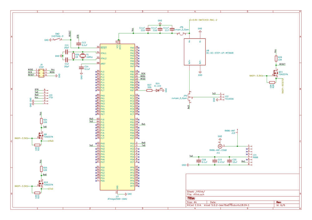
The scope of the MT3608 is to power the FS1000A radio module (433 MHz transmitter) at 10-12V, to increase the range of the signal. The MT3608 is not strictly necessary because you can power the FS1000A with the RX3 PIN of the ATMega2560, bridging pin 1 and 2 of the jumper 5 (JP5). All is explained here.
The step-down MP1584 must be set to 1.5V if it is used to power one or more 940 nm IR LED (3W - 700 mA). The details are here, below the schematic:
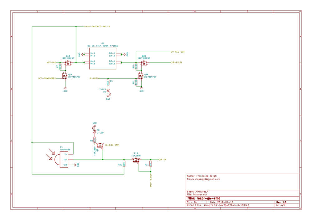
The ir-pulse rail is connected to the pin 2 (+) of the J4 connector and to the D- pin of the USB port. A single IR LED is connected to the J4 connector, but if you want to increase the coverage of the IR signal you can connect 2 or 3 additional LED with the USB port. Please note that the MP1584 is rated at 3A.
The V-REG-OUT rail is connected to the D+ pin of the USB port.
Regarding the power rails, 5V is the main voltage provided by the power supply (+5V-IN in the schematics), while for the 3.3V there are 3 different lines, to not overload the voltage regulator of the Raspberry Pi:
-
Line 1: provided by U2 (AMS1117 and its caps) and dedicated to power only the NRF24L01. In this way we have a voltage as smooth and stable as possible, to avoid problems with sensitive radio module.
-
Line 2 (RAW): provided by U6 (AMS1117 and its caps) to power the radio activity and power status LEDs
-
Line 3: provided by Raspberry Pi GPIO and used to power the RFM69 radio module.
-
-
To be honest, I think that having a dedicated 1.5V rail (with a step down switchmode) just for IR transmitter, is not an ideal solution.
- It adds extra complexity
- vFwd varies a lot, so 1.5V is not ideal for all IR diodes (it varies from 1.2V to 2V)
- How is the response of the switchmode, if you pulse high current output at 38Khz, or 455Khz? (those are the normal frequencies used by IR remotes).
- If you want to add an extender cable, for placing the LEDs a bit away from your board, you will probably need to take voltage drops accross the wires into account as well, due to higher current through the wires.
I would use 2-3 ir leds in series, depending on vFwd, and then a series resistor to limit the current (might not be needed). and then run the thing from the 5V rail, and use a n-fet as a LED driver to power the LEDs on / off, like the schematics shown in the first response here https://electronics.stackexchange.com/questions/67775/driving-led-strip-from-microcontroller
@tbowmo Thanks for your technical feedback, really appreciated!
Let me explain some points:
-
It adds extra complexity. Yes, but the board comes ready to use, so it is not a problem for the end user and the cost of the MP1584 is about 1$... Not too much respect to flexibility that it brings (see point 2)
-
vFwd varies a lot, so 1.5V is not ideal for all IR diodes (it varies from 1.2V to 2V). The output voltage range of the MP1584 is adjustable (0.8 - about 5V), so you can use any LED you want. The suggested 3W IR LED (this one) has a great range respect to the normal IR led that are used in the numerous tutorial that you can find around. In my experience the range of one or two of this normal IR LEDs is about 1 meter or less.
-
How is the response of the switchmode, if you pulse high current output at 38Khz, or 455Khz? (those are the normal frequencies used by IR remotes). I'm not so expert in electronics to give you a detailed answer, but the final results is that the circuit works. I have tested it with my Samsung smart tv (see this) and all the commands are well recognized by the TV.
-
Extension cable Remember the WAF if your plan is to run a very long cable from the USB port to the additional LEDs :grin: The main idea is that the additional LEDs (maybe with their own 3d printed case) have to be placed near the hub to cover a wider angle (360°). For long distances maybe a simple and cheap DIY IR repeater is better.
Regarding the LEDs in series with a resistor (if needed), it was an option that I have considered but rejected for this two reasons:
-
If only one LED burns out your transmitter does not work at all
-
A resistor is a waste of power, especially if your current is not negligible
Please note also that if you want to power your LEDs with 5V, you can do that simply not installing the MP1584 and then bridging the input + and output + holes of the footprint with a wire.
-
fair points..
One thing, you mention that it's 1$ for the chip.. Now imagine if you want to sell this puppy by millions, then 1$ is a lot of money ;)
Have you considered a constant current driver instead, like this one https://arduinodiy.wordpress.com/2015/12/12/driving-an-ir-led-constant-current-source-or-not/
-
One of the benefits of opening the documentation, is that others can review your design, and give you new ideas for features/implementation details, specially if you are "new" to electronics.
The link you provide for current mode led driver, is not meant to be switch on/off like the one I provided.
It also puzzles me, that you have chosen a 3W diode manufactured for nightvision? Normal small 3/5mm LEDs are just fine (that's what the RC manufacturers are using). Look at the datasheet, and peak forward current. For example this datasheet. Constant power iFwd is 100mA, but if you are using it with short pulses (like a IR transmitter, where you have a carrier freq. of 38Khz which you modulate), you can actually safely drive it with up to 500mA iFwd.
One benefit of using multiple diodes, is that you can put them on an arc, like this:
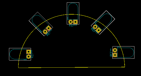
And then spread your IR signal on a larger area. -
One of the benefits of opening the documentation, is that others can review your design, and give you new ideas for features/implementation details, specially if you are "new" to electronics.
The link you provide for current mode led driver, is not meant to be switch on/off like the one I provided.
It also puzzles me, that you have chosen a 3W diode manufactured for nightvision? Normal small 3/5mm LEDs are just fine (that's what the RC manufacturers are using). Look at the datasheet, and peak forward current. For example this datasheet. Constant power iFwd is 100mA, but if you are using it with short pulses (like a IR transmitter, where you have a carrier freq. of 38Khz which you modulate), you can actually safely drive it with up to 500mA iFwd.
One benefit of using multiple diodes, is that you can put them on an arc, like this:
And then spread your IR signal on a larger area.@tbowmo Thank you for your effort! Now my turn... the whole schematics of the d-diot board is available for download here! :wink:
Of course I have to learn more and do some testing before implementing in the d-diot board the constant current source circuit that you suggested, but this a great option to eliminate the MP1584 (that one day may become unavailable on the market) and to lowering the cost. For the same reasons my plan is to substitute the step up module MT3608 with a boost converter circuit, made from standard passive components (like this).
In any case, if someone else needs to make an universal IR remote with a Raspberry Pi, the configuration of the GPIO pins of the Raspberry is here, while the steps necessary to configure LIRC and lirc_web are here.
The final results is this:
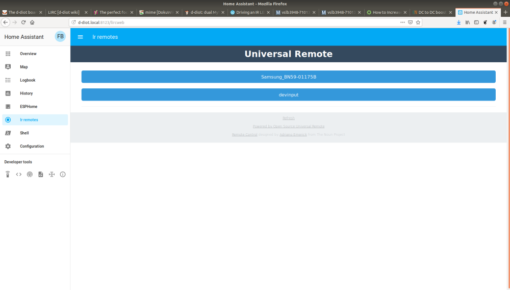
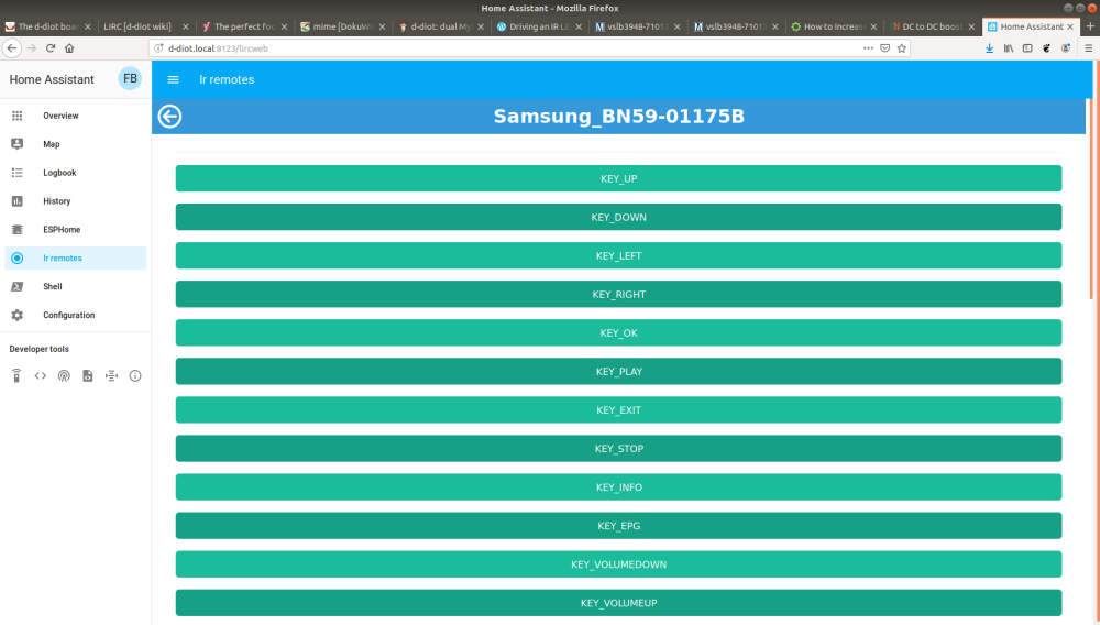
Here the guides to play with the IR gateway (add a remote, clone a remote, Home Assistant integration)
Hello! It looks like you're interested in this conversation, but you don't have an account yet.
Getting fed up of having to scroll through the same posts each visit? When you register for an account, you'll always come back to exactly where you were before, and choose to be notified of new replies (either via email, or push notification). You'll also be able to save bookmarks and upvote posts to show your appreciation to other community members.
With your input, this post could be even better 💗
Register Login