nRF24L01+ Communication Failure: Root Cause and “Solution”
-
Here is a modified RF24 stack with (among other little changes) a waiting period and no IRQ line (as @Yveaux suggested) for testing: https://github.com/tekka007/MySensors/tree/OptimizedRF24polling
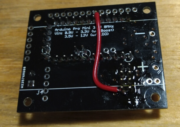
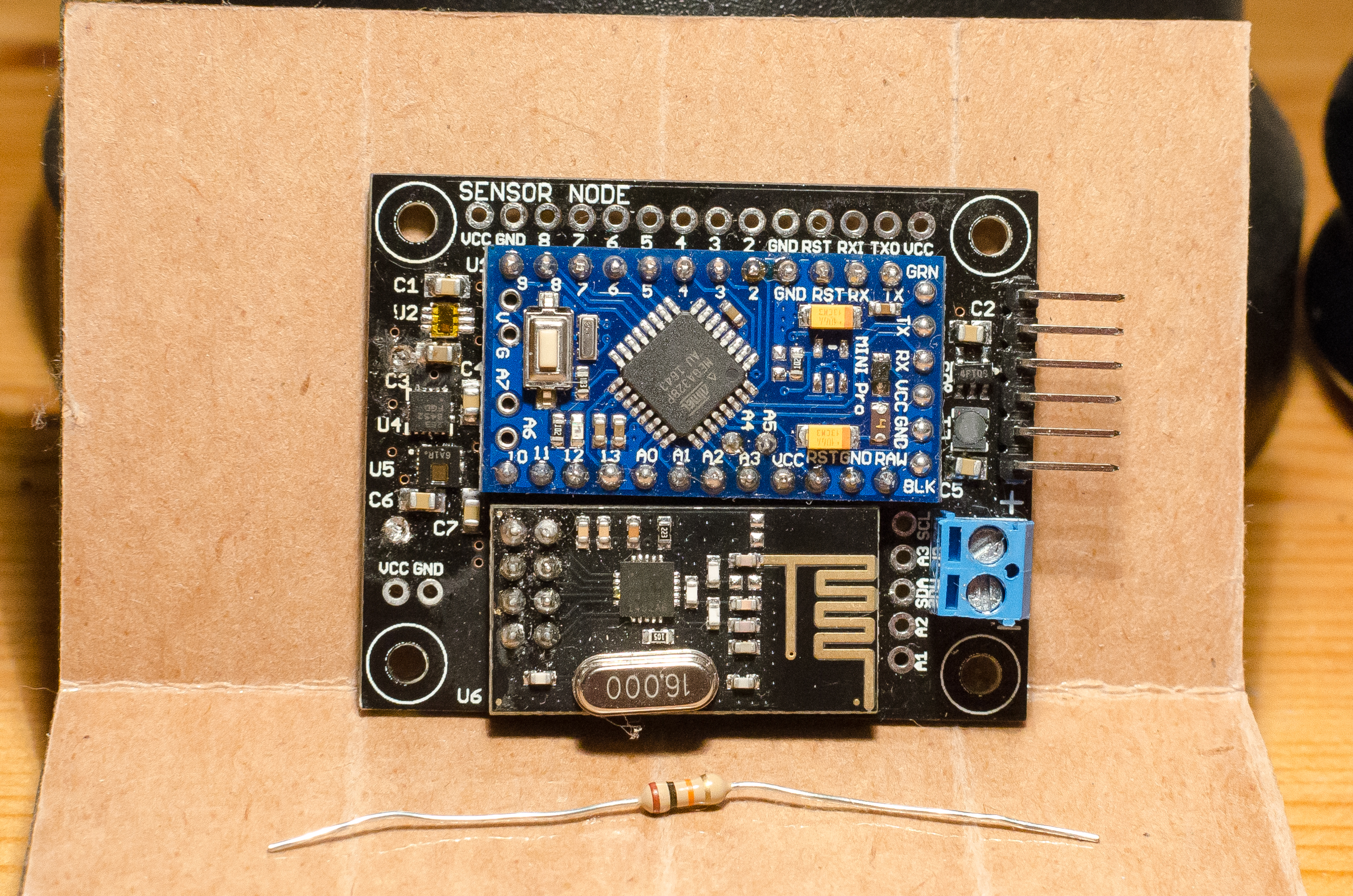
Using the previously mentioned sensor board with a header socket, we observed that almost any nRF24L01+ board worked when cabled (~6 inches) rather than directly plugging into the sensor board. (BUT WHY?????)
Is this setup referring to image 7?
@tekka I peaked at the delay you added to the RF24.cpp file. It looks like your calculation is not considering auto-ACK unless I am missing something. I have given some thought to what I think needs to be considered to completely avoid all possible transmissions. See below
optimal delay with ShockBurst = TX state transition delay + (nRF packet length * DataRate + auto-ACK timeout) * (ACKretries + 1)
optimal delay without SB = TX state transition delay + nRF packet length * DataRateThe problem I ran into doing a static delay is that the delay time can get quite large if considering ACK retires making the system very slow. Reducing the amount of polling should help interference even if all SPI communication isn't avoided during every possible transmission. I would definitely prefer the IRQ line used if defined and if not then use a delay (either with or without retires in mind).
-
@Yveaux To be clear, I realize my code snippet "fix" would break anyone who doesn't already have the IRQ hooked up. This is where we are asking for a contributor more experienced with generalizing to the MySensors library and looking for #defines or such to play nice.
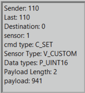
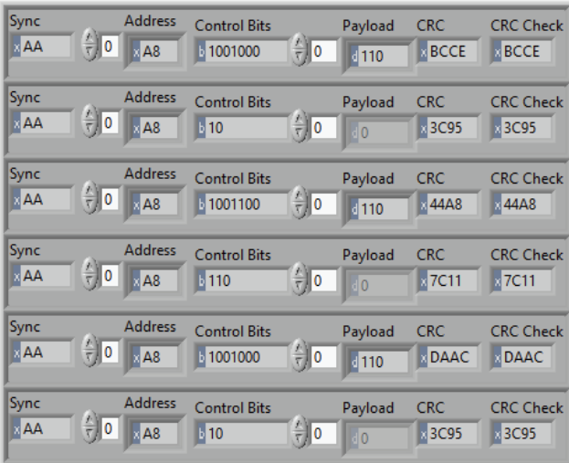
As for what is different between image 6 and image 7 I admit our description in that section gets a little hand wavy for brevity. Image 7 is an auto-ACK from the nRF24L01+ ShockBurst where Image 6 is an outgoing message. You can see evidence of this in image 3 where outgoing messages (like image 6) have a payload (containing MySensors info) and auto-ACKs have no payload (shown as a grey'd out array).
Once I saw that the hardware transmission can be pristine it started me thinking what was so different between a normal message and an auto-ACK. SPI communication.
A word of caution reading too much into early debug steps mentioned (just before image 2). We decided to include these to give background information on what kinds of troubleshooting steps we tried. Some were tried out of sleep deprived desperation and what appeared to "fix" the problem at the time may have only modified the conditions that didn't work. We were not into "rigorous testing mode" at this point in time. We were blindly stabbing in the dark hoping something would work. Additionally, these early debug steps were done without any knowledge of other spectral content in the environment. Once we started using the SDR we observed the spectrum first and moved the nRF channel in a clear and free band to ensure our measurements were only of the nRF boards.
@odritter said in nRF24L01+ Communication Failure: Root Cause and “Solution”:
it started me thinking what was so different between a normal message and an auto-ACK. SPI communication.
And the all important fact that the ack message on air comes from the receiving node, instead of the sending one.
My gut feeling tells me you are masking a hardware (design) flaw with software. If it helps in your case, good for you, but I'd like to understand it completely before absorbing it in the stack.http://yveaux.blogspot.nl
-
@tekka I have been testing this (2.3.2b) on a node for the last 9.5 hours and so far no problems.
I will probably flash the GW with this today and see how that goes, not expecting any issues though! ;)
One question though..... Does this 'fix' also apply to when the nrf is in Rx mode as well? If there is no spi activity during Rx then I guess it's a moot point. But I'd be interested in the answer.
-
@odritter said in nRF24L01+ Communication Failure: Root Cause and “Solution”:
it started me thinking what was so different between a normal message and an auto-ACK. SPI communication.
And the all important fact that the ack message on air comes from the receiving node, instead of the sending one.
My gut feeling tells me you are masking a hardware (design) flaw with software. If it helps in your case, good for you, but I'd like to understand it completely before absorbing it in the stack. -
@odritter said in nRF24L01+ Communication Failure: Root Cause and “Solution”:
it started me thinking what was so different between a normal message and an auto-ACK. SPI communication.
And the all important fact that the ack message on air comes from the receiving node, instead of the sending one.
My gut feeling tells me you are masking a hardware (design) flaw with software. If it helps in your case, good for you, but I'd like to understand it completely before absorbing it in the stack.@yveaux I agree this fix may be covering up a problem in our design. As @mfalkvidd mentioned in his post we did put the antenna in an unusual location (not ideal). So it is entirely possible our problems are caused by the antenna placement, nRF clones, or something else entirely. However, we believe we are not alone in the issues we encountered or any design flaw we made.
That being said, constantly polling during TX transmission should be avoided as it is unnecessary. MySensors can calculate how long a transmission should take and hold off for a least the first (or all possible) transmission(s). Implementing a delay should be minimal risk and can only benefit. Implementing the IRQ is more involved to implement properly and higher risk (though I think worth it).
-
@tekka I have been testing this (2.3.2b) on a node for the last 9.5 hours and so far no problems.
I will probably flash the GW with this today and see how that goes, not expecting any issues though! ;)
One question though..... Does this 'fix' also apply to when the nrf is in Rx mode as well? If there is no spi activity during Rx then I guess it's a moot point. But I'd be interested in the answer.
@skywatch This fix only applies to the TX for three reasons.
- Our method for measuring transmission quality can only observe TX (not RX) so we would need a different way to assess RX
- TX timing is well known from start to finish so muting the communication while it is happening is relatively straightforward. RX is a different story
- MySensors already implements IRQ for RX and likely already gains whatever benefit there is to be had limiting communication during RX (though I didn't look into this extensively to confirm)
I am open to ideas on how to assess the RX side if anyone has any suggestions. However for us, implementing the IRQ fix for TX made our boards go from barely working to working like a champ!
-
@odritter Thanks for the clarification! - I learn something new (again)... :)
My question was based on the fact that if enough energy is present in the spi signal to imprint on the Tx output, then it would be even worse for the Rx side as the levels of signal received would be much lower than anything transmitted.
-
@yveaux I agree this fix may be covering up a problem in our design. As @mfalkvidd mentioned in his post we did put the antenna in an unusual location (not ideal). So it is entirely possible our problems are caused by the antenna placement, nRF clones, or something else entirely. However, we believe we are not alone in the issues we encountered or any design flaw we made.
That being said, constantly polling during TX transmission should be avoided as it is unnecessary. MySensors can calculate how long a transmission should take and hold off for a least the first (or all possible) transmission(s). Implementing a delay should be minimal risk and can only benefit. Implementing the IRQ is more involved to implement properly and higher risk (though I think worth it).
@odritter said in nRF24L01+ Communication Failure: Root Cause and “Solution”:
constantly polling during TX transmission should be avoided as it is unnecessary
There is no mention in the nRF24L01+ datasheet of (potential) issues caused by SPI transfers during TX, so where is your statement based on?
-
@odritter said in nRF24L01+ Communication Failure: Root Cause and “Solution”:
it started me thinking what was so different between a normal message and an auto-ACK. SPI communication.
And the all important fact that the ack message on air comes from the receiving node, instead of the sending one.
My gut feeling tells me you are masking a hardware (design) flaw with software. If it helps in your case, good for you, but I'd like to understand it completely before absorbing it in the stack.@yveaux I would be happy to provide our schematic and layout details if you think it would be helpful in identifying the hardware design flaw we made. If there is something we could do to fix this with a board change, that would be interesting to know/consider. (Especially if it ends up being mistake that is commonly made by others using who are also using the nRF24 Board).
Alternatively, it could be an issue with our specific nRF24L01+ boards. While we did order some from Amazon and some from AliExpress, out best guess is that they are all counterfeit/clones. If you know of a source where we could order a board that in confidently authentic, that would be an interesting experiment as well.
-
@yveaux I would be happy to provide our schematic and layout details if you think it would be helpful in identifying the hardware design flaw we made. If there is something we could do to fix this with a board change, that would be interesting to know/consider. (Especially if it ends up being mistake that is commonly made by others using who are also using the nRF24 Board).
Alternatively, it could be an issue with our specific nRF24L01+ boards. While we did order some from Amazon and some from AliExpress, out best guess is that they are all counterfeit/clones. If you know of a source where we could order a board that in confidently authentic, that would be an interesting experiment as well.
@ben036 I would certainly like to have a look at your design files.
You could give Ebyte modules a try : https://forum.mysensors.org/topic/9668/cdebyte-s-new-nrf24-modules-are-great-and-cheap
I have very good experience with these, and are probably using authentic nrf24's -
@ben036 I would certainly like to have a look at your design files.
You could give Ebyte modules a try : https://forum.mysensors.org/topic/9668/cdebyte-s-new-nrf24-modules-are-great-and-cheap
I have very good experience with these, and are probably using authentic nrf24's -
@odritter said in nRF24L01+ Communication Failure: Root Cause and “Solution”:
constantly polling during TX transmission should be avoided as it is unnecessary
There is no mention in the nRF24L01+ datasheet of (potential) issues caused by SPI transfers during TX, so where is your statement based on?
@yveaux My statement is based on the assumption that everything can interfere with your desired signal. It's just a matter of how much. It's very possible that genuine nRF boards are less susceptible to the interference we have shown. However, all the nRF boards we have are suspected clones so I do not have a way to direct compare clone vs genuine (unless we purchase from the Ebyte link you provided).
I have provided a link below to a public application note I came across that provides some background information on sources of interference and how it impacts your desired signal/receiver. Unfortunately it gets very technical at times and assumes a large amount of base RF knowledge so its usefulness may be limited. Nonetheless, I thought I would share if anyone was interested.
Testing and Troubleshooting Digital RF Communications Receiver Designs
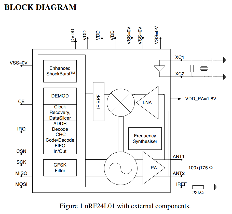
The nRF uses a sampled IF receiver as described in section 1.2.2 and similar
to what is shown in figure 4. Section 3.2.2 covers some interfering signals but mostly talks about more complex modulation schemes than the nRF uses.I went back and did an additional experiment using only our Gateway and the Software Defined Radio (SDR) to measure interference on something other than our sensor PCB.
My setup:
Gateway=RaspberryPi 3 with cabled nRF24L01+ hanging out in free space
SDR=USRP B210 with 2.4GHz Vertical antenna
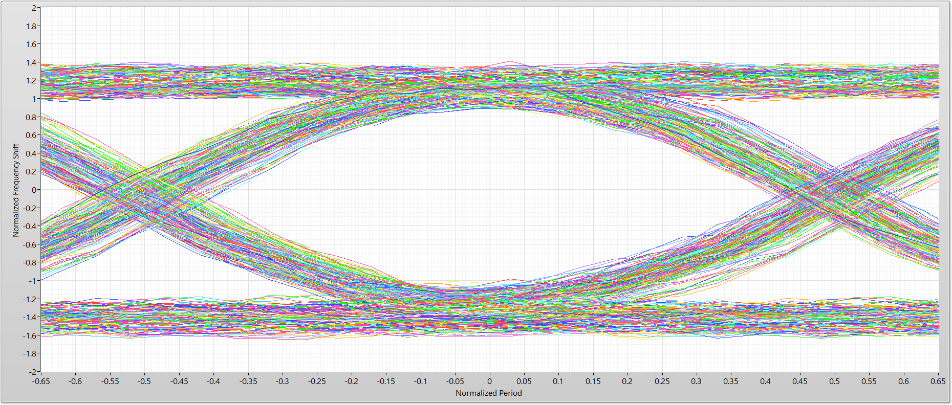
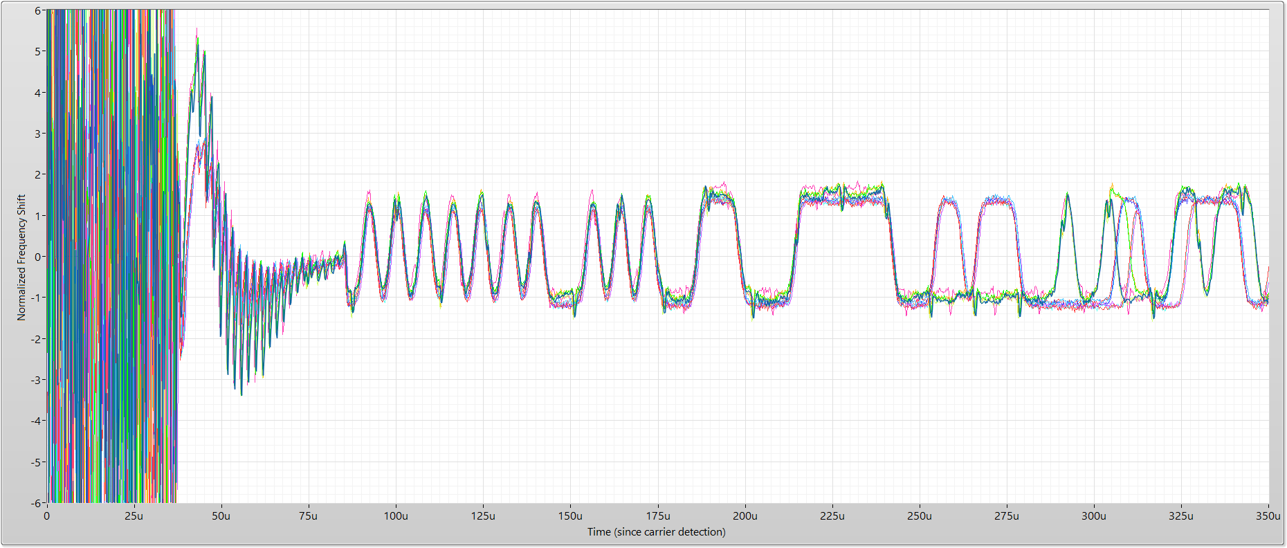
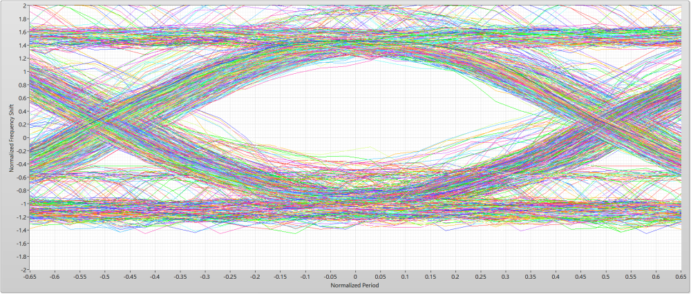
Gateway and SDR placed about 2 feet apart in the middle of a roomGateway transmitted 16 packets for both graphs. The only difference between the two graphs: upper graph constantly polls TX status where the lower graph uses the IRQ line to wait for completion. The physical hardware setup was unchanged between the two measurements.
TX Status Polling
IRQ Wait
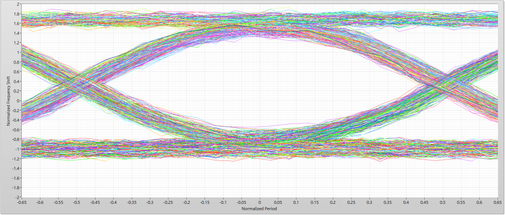
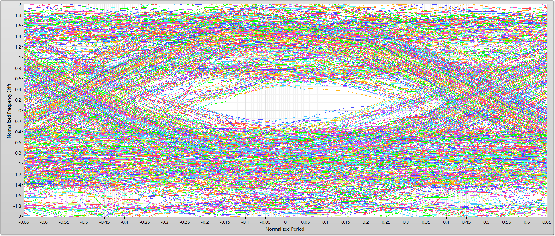
These data Eye patterns were taken with a single nRF board (in contrast, the Eye patterns included in the original post are a composite of 10 different nRF boards)
-
@odritter Thanks for the clarification! - I learn something new (again)... :)
My question was based on the fact that if enough energy is present in the spi signal to imprint on the Tx output, then it would be even worse for the Rx side as the levels of signal received would be much lower than anything transmitted.
@skywatch said in nRF24L01+ Communication Failure: Root Cause and “Solution”:
@odritter Thanks for the clarification! - I learn something new (again)... :)
My question was based on the fact that if enough energy is present in the spi signal to imprint on the Tx output, then it would be even worse for the Rx side as the levels of signal received would be much lower than anything transmitted.
It certainly is possible the Rx side could be even worse. However, it strongly depends on where the interference is coming in. For instance, if the interference happened before the Low Noise Amplifier (LNA) then it would very likely be just as bad or even worse. However, if the interference happened after the LNA it may not have anywhere near as much impact since the signal should be much larger. Though, if the interference impacted the digitization (not really shown in the block diagram explicitly) then it would likely have a significant impact.
Thinking about the TX side of things, the interference is very likely occurring before the modulator (to the left of the PA) since I can "see" the SPI interference with the SDR after it has been demodulated. I have included the nRF block diagram from the datasheet below for reference.
-
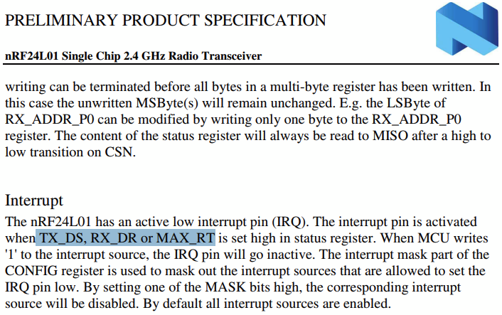
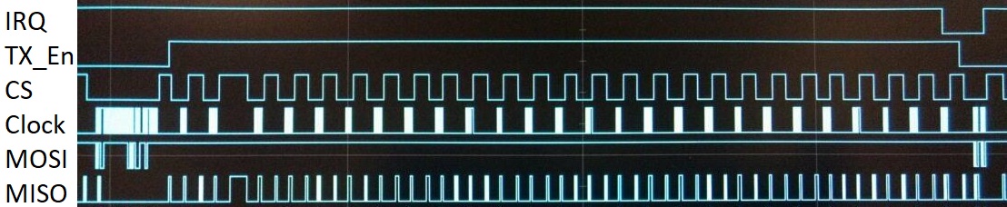
@odritter What puzzles me is that the interference in image 6 apparently isn't always present (see image 7), although the behavior of the MySensors stack is always identical (see image 8 and the matching code snippet 1).
Do you see a pattern when it is present and when not?Also, switching to using the nRF24 interrupt line will break MySensors for a lot of (existing) boards, that don't have the IRQ line connected.
So, if we decide to add a silent period to the stack, we also need a non-IRQ implementation based on e.g. a delay.@yveaux said in nRF24L01+ Communication Failure: Root Cause and “Solution”:
@odritter What puzzles me is that the interference in image 6 apparently isn't always present (see image 7), although the behavior of the MySensors stack is always identical (see image 8 and the matching code snippet 1).
Do you see a pattern when it is present and when not?Also, switching to using the nRF24 interrupt line will break MySensors for a lot of (existing) boards, that don't have the IRQ line connected.
So, if we decide to add a silent period to the stack, we also need a non-IRQ implementation based on e.g. a delay.Indeed, the RF Nano has no connected IRQ pins (and uses the NRF24 non-plus version..).
Although it may be unrelated, it's fascinating that this is another instance of MySensors being 'too fast', and 'needing a delay' to work better.
-
@yveaux said in nRF24L01+ Communication Failure: Root Cause and “Solution”:
@odritter What puzzles me is that the interference in image 6 apparently isn't always present (see image 7), although the behavior of the MySensors stack is always identical (see image 8 and the matching code snippet 1).
Do you see a pattern when it is present and when not?Also, switching to using the nRF24 interrupt line will break MySensors for a lot of (existing) boards, that don't have the IRQ line connected.
So, if we decide to add a silent period to the stack, we also need a non-IRQ implementation based on e.g. a delay.Indeed, the RF Nano has no connected IRQ pins (and uses the NRF24 non-plus version..).
Although it may be unrelated, it's fascinating that this is another instance of MySensors being 'too fast', and 'needing a delay' to work better.
@alowhum said in nRF24L01+ Communication Failure: Root Cause and “Solution”:
MySensors being 'too fast', and 'needing a delay' to work better.
Let's not jump to conclusions too fast!
So far there's only measurement data of one case where reducing SPI traffic during TX appears to reduce noise; this makes it very likely that the issue is hardware related (SPI lines run directly below the nRF24 board, the nRF24 board is placed next to the Pro Mini SPI lines (pins 10-13) and nRF24 modules are of questionable origin).
The fact that increasing the distance between nRF24 and board by jumper wire improves the transmission success rate is a clear indication this issue is hardware related.Still, reducing potential disturbances during transmission and reception is important, especially if all MySensors users can potentially benefit from it with no or minimal penalty.
The MySensors stack however needs to support different hardware variations, with and without IRQ line connected.
The TX case with IRQ connected is trivial to solve, when IRQ is not connected is less trivial IMHO.
When using nRF24 with hardware ACK the actual TX time is not known upfront due to potential retries; we can only calculate a lower and upper bound.
Always silencing SPI communication for the upper time bound makes the node slow, shorter wait times require polling the nRF24 over SPI, thus introducing potential disturbance. The patch by @tekka reduces the polling rate and limits the upper bound (the number of hardware ACK retries), still it delays the TX time compared to the latest 2.3 release implementation.
Another solution could be limiting the SPI clock rate during the TX polling time, which also potentially improves RX polling.As always, there is no one size fits all solution ;-)
@odritter MySensors Core team has a number of SDRs and genuine nRF24's at their disposal. Do you have a description how to derive the eye pattern so others can replicate your setup?
-
@Yveaux Point taken.
I also agree that it should still work on non-IRQ scenario's, as that's pretty much my scenario now that I switched to the RF Nano.
Out of curiosity: what would be 'slow' in this scenario? Are we talking milliseconds? Hundreds?
And could this issue be related in any way?
-
@Yveaux Point taken.
I also agree that it should still work on non-IRQ scenario's, as that's pretty much my scenario now that I switched to the RF Nano.
Out of curiosity: what would be 'slow' in this scenario? Are we talking milliseconds? Hundreds?
And could this issue be related in any way?
@alowhum said in nRF24L01+ Communication Failure: Root Cause and “Solution”:
Out of curiosity: what would be 'slow' in this scenario? Are we talking milliseconds? Hundreds?
As always; it depends on a number of things, e.g. radio bitrate, maximum number of retries, message length. I would have to do some calculations to get an indication.
And could this issue be related in any way?
No. I suspect #941 and #1134 are related.
-
@alowhum
for older nodes, it would need retrocompatibility, but imho, when you get started in MySensors, it's bad hardware choice to not connect the radio irq signal. It's also mentioned in MySensors doc it's better to use it.Why someone wouldn't like better communication for his HA??
to be precise why someone in 2019 would like to use nrf24+low 328p ? :japanese_ogre: :smile:With irq events instead of always-polling, you get queue management for messages. And also smoother processing, better states sync, more reactive just in time, not delayed or at the wrong moment, using resources only when needed.
So,to start out on the right foot , I would strongly advice people/newcomers to connect irq when possible, and for new nodes (it's mandatory for rfm69).
-
@alowhum said in nRF24L01+ Communication Failure: Root Cause and “Solution”:
MySensors being 'too fast', and 'needing a delay' to work better.
Let's not jump to conclusions too fast!
So far there's only measurement data of one case where reducing SPI traffic during TX appears to reduce noise; this makes it very likely that the issue is hardware related (SPI lines run directly below the nRF24 board, the nRF24 board is placed next to the Pro Mini SPI lines (pins 10-13) and nRF24 modules are of questionable origin).
The fact that increasing the distance between nRF24 and board by jumper wire improves the transmission success rate is a clear indication this issue is hardware related.Still, reducing potential disturbances during transmission and reception is important, especially if all MySensors users can potentially benefit from it with no or minimal penalty.
The MySensors stack however needs to support different hardware variations, with and without IRQ line connected.
The TX case with IRQ connected is trivial to solve, when IRQ is not connected is less trivial IMHO.
When using nRF24 with hardware ACK the actual TX time is not known upfront due to potential retries; we can only calculate a lower and upper bound.
Always silencing SPI communication for the upper time bound makes the node slow, shorter wait times require polling the nRF24 over SPI, thus introducing potential disturbance. The patch by @tekka reduces the polling rate and limits the upper bound (the number of hardware ACK retries), still it delays the TX time compared to the latest 2.3 release implementation.
Another solution could be limiting the SPI clock rate during the TX polling time, which also potentially improves RX polling.As always, there is no one size fits all solution ;-)
@odritter MySensors Core team has a number of SDRs and genuine nRF24's at their disposal. Do you have a description how to derive the eye pattern so others can replicate your setup?
@yveaux I can certainly provide details for others to replicate. For completeness I am including details beyond just Eye diagram creation. See below
My setup:
- nRF24L01+ (clone)
** #define MY_RF24_PA_LEVEL RF24_PA_HIGH
** #define MY_RF24_DATARATE RF24_250KBPS
** #define MY_RF24_CHANNEL 30
** #define MY_RF24_IRQ_PIN 4 - SDR: USRP B210 with 2.4GHz vertical antenna
** 5MHz bandwidth centered at 2.43GHz (for channel 30)
** Eye diagrams require oversampling to build a meaningful eye. I would recommend a minimum 10x oversampling if possible (5MHz BW at 250KBPS yields 20x) - Processing:
** Capture waveform with desired transmission (my setup can't trigger on anything specific, so I looked at signal power to trim down the record)
** Detect and remove carrier frequency offset - I used "0xAAA8" as a sync word
** Perform FM demodulation normalizing to expected frequency shift (±160kHz at 250KBPS)
** Find the center of the eye - this is done by looking for the location with the highest correlation to the sync word (or can be manually found)
** To build the Eye diagram, "chop" up the waveform at the crossing points which are located at ±(0.5*OversampleRate) samples from Eye center (±10 samples in my case)
** Overlay resulting waveforms on top of one another to form the Eye diagram
See image below for demonstration. Dashed red lines are where the waveform should be chopped:
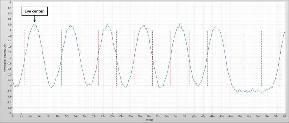
I used LabVIEW with the Modulation Toolkit to perform my measurements. I can provide my code if helps though I suspect you probably use GNU Radio. I can provide additional details if something isn't clear or I left something out.
What metric do you currently use to measure link quality?
- nRF24L01+ (clone)
-
@yveaux I can certainly provide details for others to replicate. For completeness I am including details beyond just Eye diagram creation. See below
My setup:
- nRF24L01+ (clone)
** #define MY_RF24_PA_LEVEL RF24_PA_HIGH
** #define MY_RF24_DATARATE RF24_250KBPS
** #define MY_RF24_CHANNEL 30
** #define MY_RF24_IRQ_PIN 4 - SDR: USRP B210 with 2.4GHz vertical antenna
** 5MHz bandwidth centered at 2.43GHz (for channel 30)
** Eye diagrams require oversampling to build a meaningful eye. I would recommend a minimum 10x oversampling if possible (5MHz BW at 250KBPS yields 20x) - Processing:
** Capture waveform with desired transmission (my setup can't trigger on anything specific, so I looked at signal power to trim down the record)
** Detect and remove carrier frequency offset - I used "0xAAA8" as a sync word
** Perform FM demodulation normalizing to expected frequency shift (±160kHz at 250KBPS)
** Find the center of the eye - this is done by looking for the location with the highest correlation to the sync word (or can be manually found)
** To build the Eye diagram, "chop" up the waveform at the crossing points which are located at ±(0.5*OversampleRate) samples from Eye center (±10 samples in my case)
** Overlay resulting waveforms on top of one another to form the Eye diagram
See image below for demonstration. Dashed red lines are where the waveform should be chopped:
I used LabVIEW with the Modulation Toolkit to perform my measurements. I can provide my code if helps though I suspect you probably use GNU Radio. I can provide additional details if something isn't clear or I left something out.
What metric do you currently use to measure link quality?
@odritter said in nRF24L01+ Communication Failure: Root Cause and “Solution”:
I suspect you probably use GNU Radio.
That's correct. To be frank, I was hoping for a simple gnu radio script that I could just run to get the pattern out. There is manual work and LabVIEW involved (which I do not have access to) so it would take some experimentation to get the same results.
Thanks for your description though!
At the moment I don't have a way to measure signal quality accurately for nrf24. Of course there's the transmission retry counter, but I found that in general it either requires a few retries at most or goes up to the maximum and fails.
- nRF24L01+ (clone)
Hello! It looks like you're interested in this conversation, but you don't have an account yet.
Getting fed up of having to scroll through the same posts each visit? When you register for an account, you'll always come back to exactly where you were before, and choose to be notified of new replies (either via email, or push notification). You'll also be able to save bookmarks and upvote posts to show your appreciation to other community members.
With your input, this post could be even better 💗
Register Login