
edited: 4 diy dimmer module. should i make icsp or serial programming connections, both?
-
I am building a 4 ch. pwm led dimmer. It's predessor used the PWM outputs from the arduino pro mini, but when ever I am filming or taking a picture I can not dim the light's and when I want to use it as a nightlight I realise there are only 256 steps. Which is not enough.
The PCA9685 is capable of 4096 steps and 1600Hz. Which is not perfect but a huge step forward.
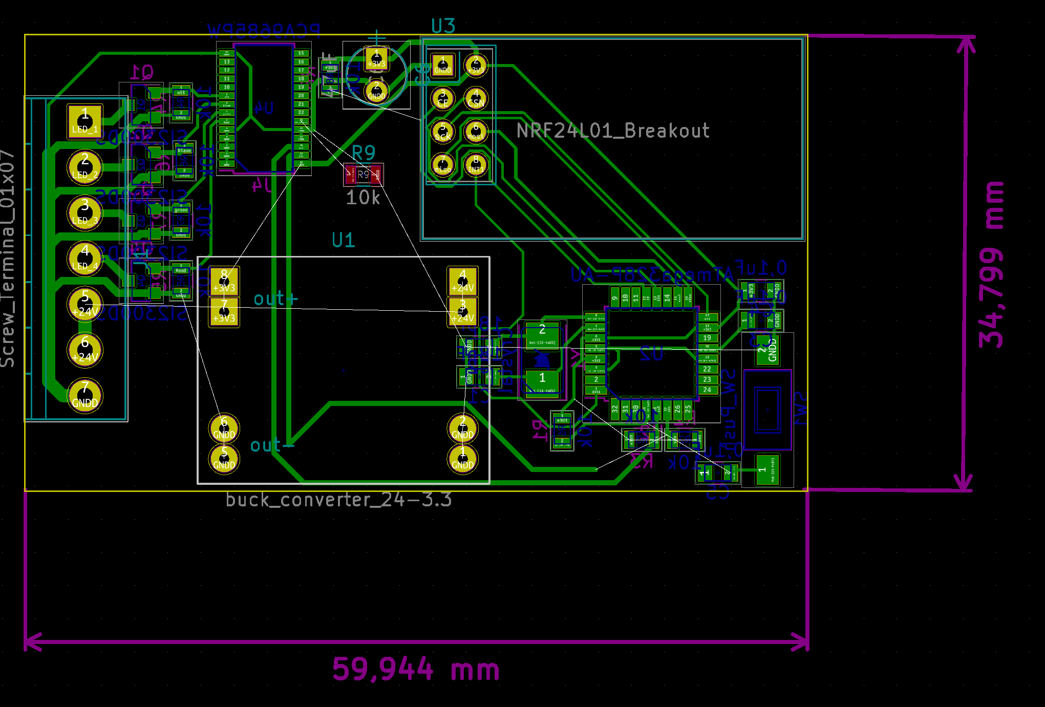
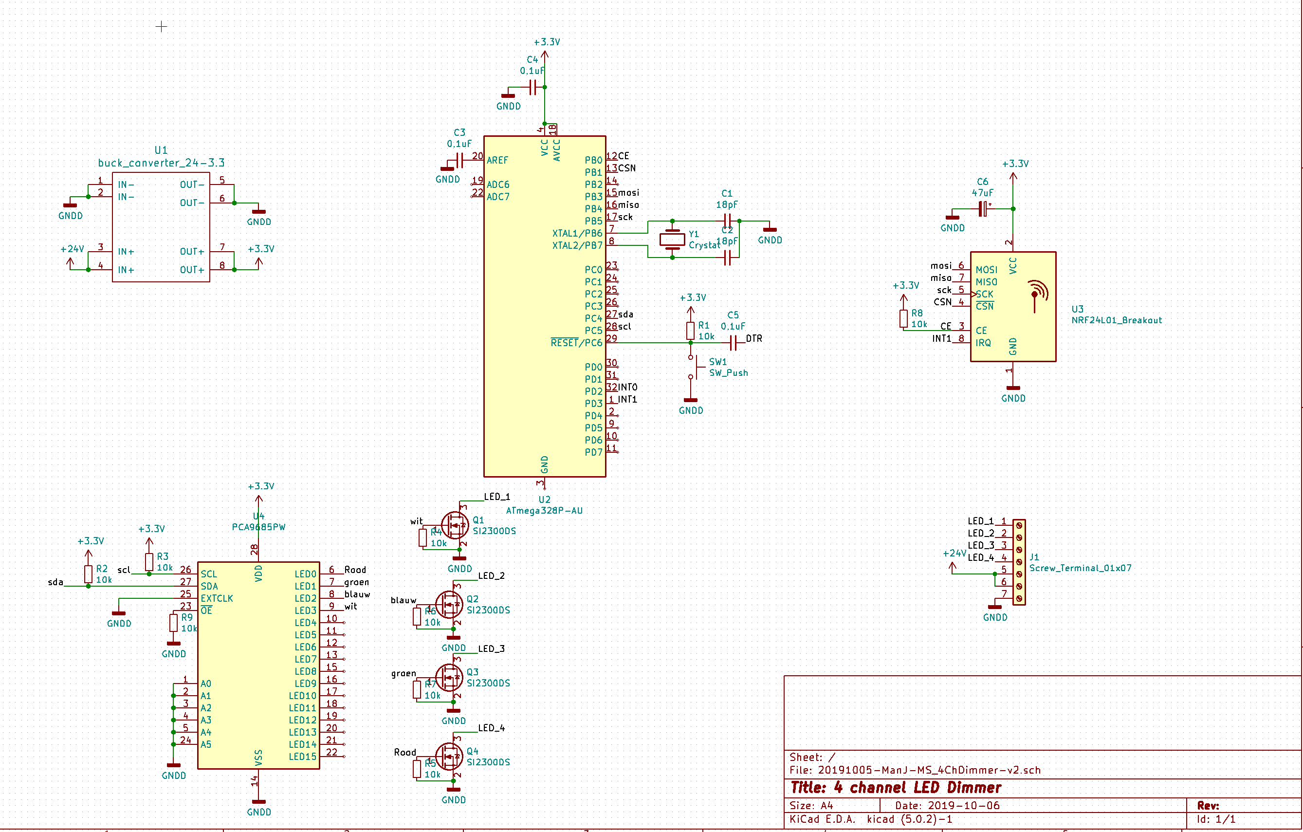
I am not using the arduino pro mini board anymore for the first time. I want to use the bare chip. There is a lot of room on the pcb, but I have yet to do a connector or pads for programming. I ask you to check my scematic and advice one icsp & serial programming connections.
The layout is somewhat similer to the previous version. The tracks that are now under the NRFmodule will be replaced somewhere else. It wil be a double layered board so there a no problems routing. This was sort of my quick and dirty routing.
-
I am building a 4 ch. pwm led dimmer. It's predessor used the PWM outputs from the arduino pro mini, but when ever I am filming or taking a picture I can not dim the light's and when I want to use it as a nightlight I realise there are only 256 steps. Which is not enough.
The PCA9685 is capable of 4096 steps and 1600Hz. Which is not perfect but a huge step forward.
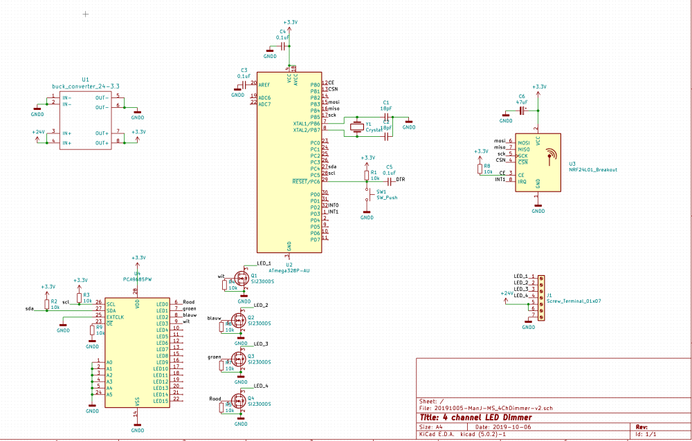
I am not using the arduino pro mini board anymore for the first time. I want to use the bare chip. There is a lot of room on the pcb, but I have yet to do a connector or pads for programming. I ask you to check my scematic and advice one icsp & serial programming connections.
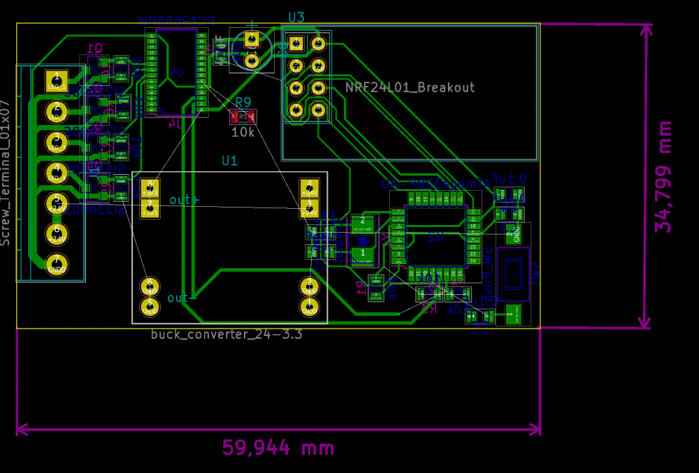
The layout is somewhat similer to the previous version. The tracks that are now under the NRFmodule will be replaced somewhere else. It wil be a double layered board so there a no problems routing. This was sort of my quick and dirty routing.
@joerideman what code are you using to run the 9685 chip? I'm looking to build a multi rgb strip controller but having problems finding mysensors code to use as an example to talk to the 9685. Any help is greatly appreciated! thanks.
-
I am using an adafruit library to communicate with the ic.
I am not cascading them, so I have no idea how to do that part. But controller 1 of them is easy. And when I have my pcb's design finished and ordered and all the parts at home, I will come up with a protocol of how the lights should respond to mysensor messages.
/*************************************************** This is an example for our Adafruit 16-channel PWM & Servo driver GPIO test - this will set a pin high/low Pick one up today in the adafruit shop! ------> http://www.adafruit.com/products/815 These drivers use I2C to communicate, 2 pins are required to interface. Adafruit invests time and resources providing this open source code, please support Adafruit and open-source hardware by purchasing products from Adafruit! Written by Limor Fried/Ladyada for Adafruit Industries. BSD license, all text above must be included in any redistribution ****************************************************/ #include <Wire.h> #include <Adafruit_PWMServoDriver.h> // called this way, it uses the default address 0x40 //Adafruit_PWMServoDriver pwm = Adafruit_PWMServoDriver(); // you can also call it with a different address you want Adafruit_PWMServoDriver pwm = Adafruit_PWMServoDriver(0x41); // you can also call it with a different address and I2C interface //Adafruit_PWMServoDriver pwm = Adafruit_PWMServoDriver(0x40, &Wire); void setup() { Serial.begin(9600); Serial.println("GPIO test!"); pwm.begin(); pwm.setPWMFreq(1600); // Set to whatever you like, we don't use it in this demo! // if you want to really speed stuff up, you can go into 'fast 400khz I2C' mode // some i2c devices dont like this so much so if you're sharing the bus, watch // out for this! Wire.setClock(400000); } void loop() { delay(1000); // Drive each pin in a 'wave' for (uint16_t waarde=0; waarde <4000; waarde++) { pwm.setPin(0,waarde); // turns pin fully on delay(5); } delay(500); for (uint16_t waarde=4000; waarde >0; waarde--) { pwm.setPin(0,waarde); // turns pin fully on delay(5); } }``` -
Thanks, I guess what i am trying to find out is how i get my sensors code to use the Adafruit_PWMServoDriver code to do the same as you than. I would like to control 5 sets of RGB strips by 5 separate V_RGB faders in domoticz using my sensors. But i cant figure out how to get mysensors to tell the PCA9685 chip how to controll the channels.

Hello! It looks like you're interested in this conversation, but you don't have an account yet.
Getting fed up of having to scroll through the same posts each visit? When you register for an account, you'll always come back to exactly where you were before, and choose to be notified of new replies (either via email, or push notification). You'll also be able to save bookmarks and upvote posts to show your appreciation to other community members.
With your input, this post could be even better 💗
Register Login