Solar Energy Harvesting for wireless motes
-
This new thread is a continuation of an earlier discussion started here: https://forum.mysensors.org/topic/6862/effective-solar-supercap-boost-charger-for-small-solar-panel/72
Something interesting: if you want to minimize the voltage drop across your solar cell's blocking diode, pick a schottky that's rated for high current (even if you're sending low current through it): https://electronics.stackexchange.com/questions/439792/diode-type-with-lowest-drop-voltage
-
I added an alternative LDO (tolerant of input voltages up to 30v) to the BOM for: https://www.openhardware.io/view/620/Supercap-solar-charger
so that up to 4 of the keychain solar cells can be linked in series and yet still managed as a single input. -
Hello! :)
The topic of powering MySensors nodes with solar energy interests me and I have been looking for solutions lately to do so.
I have found an awesome energy harvesting chip with a lot of features to create hassle-free solar-powered devices. It's called the AEM10941 by e-peas.
What is really great with this chip is that it takes a solar cell as input, charges a battery / supercapacitor and outputs two stable selectable voltages. So it does energy harvesting & boost / buck converter.
Moreover, if the sun isn't shining for a long period of time, you can also add a "backup battery" that will be used when your rechargeable medium runs out of juice.Jasper Sikken built a nice board during the Hackaday "energy harvesting" competition with this chip: https://hackaday.io/project/159139-tiny-solar-energy-module-tsem. As you can see, it requires very few components, which is great!
I plan to use this chip for my outdoor weather station that I am building with MySensors (I have a BME280 which measures temperature, humidity & pressure). I'll very probably build my own board with 2.54mm-spaced pins to manipulate it more easily! :)
Come have fun with me on IRC: #mysensors on Libera.chat :)
-
Hello! :)
The topic of powering MySensors nodes with solar energy interests me and I have been looking for solutions lately to do so.
I have found an awesome energy harvesting chip with a lot of features to create hassle-free solar-powered devices. It's called the AEM10941 by e-peas.
What is really great with this chip is that it takes a solar cell as input, charges a battery / supercapacitor and outputs two stable selectable voltages. So it does energy harvesting & boost / buck converter.
Moreover, if the sun isn't shining for a long period of time, you can also add a "backup battery" that will be used when your rechargeable medium runs out of juice.Jasper Sikken built a nice board during the Hackaday "energy harvesting" competition with this chip: https://hackaday.io/project/159139-tiny-solar-energy-module-tsem. As you can see, it requires very few components, which is great!
I plan to use this chip for my outdoor weather station that I am building with MySensors (I have a BME280 which measures temperature, humidity & pressure). I'll very probably build my own board with 2.54mm-spaced pins to manipulate it more easily! :)
-
There is a "Where to buy" button at the top of the page I linked.
As you can see on, the page, they can be bought worldwide on the Fujitsu webshop for €4 per unit: https://shop.feeu.com/epages/es966226.sf/en_GB/?ObjectPath=/Shops/es966226/Products/AEM10941
You can also buy the "ready to use" board built and sold by Jasper Sikken on Tindie:
- The supercapaciors version: https://www.tindie.com/products/jaspersikken/solar-harvesting-into-supercapacitors/
- The lithium-ion version: https://www.tindie.com/products/jaspersikken/solar-harvesting-into-li-ion-battery/
They are a bit expensive though (€22.60 each), that's why I'm considering building my own boards.
I've just found now that he has posted the schematics on GitHub, that's great:
Come have fun with me on IRC: #mysensors on Libera.chat :)
-
There is a "Where to buy" button at the top of the page I linked.
As you can see on, the page, they can be bought worldwide on the Fujitsu webshop for €4 per unit: https://shop.feeu.com/epages/es966226.sf/en_GB/?ObjectPath=/Shops/es966226/Products/AEM10941
You can also buy the "ready to use" board built and sold by Jasper Sikken on Tindie:
- The supercapaciors version: https://www.tindie.com/products/jaspersikken/solar-harvesting-into-supercapacitors/
- The lithium-ion version: https://www.tindie.com/products/jaspersikken/solar-harvesting-into-li-ion-battery/
They are a bit expensive though (€22.60 each), that's why I'm considering building my own boards.
I've just found now that he has posted the schematics on GitHub, that's great:
@encrypt said in Solar Energy Harvesting for wireless motes:
There is a "Where to buy" button at the top of the page I linked.
As you can see on, the page, they can be bought worldwide on the Fujitsu webshop for €4 per unit: https://shop.feeu.com/epages/es966226.sf/en_GB/?ObjectPath=/Shops/es966226/Products/AEM10941
Yes thank you, I have seen that but I hoped there would be another source for the bare chip. I have to enter all my personal information to create an account and have an idea of the shipping price, which is annoying. Can you or anyone else with already an account check how much the shipping is for a few units for "non EU" destination ? Thank you !
-
Here's my current thinking on what to do next:
https://www.openhardware.io/dl/5b8ff8a3d376570b051a91ed/design/schematic_solarLDO_v000.pdfIt's a roll-my-own LDO, which has two advantages: 1. I can pick whatever maximum voltage I want for the solar input (I'm thinking a max of 40v would cover everything), and 2. It gives me access to the charge finished signal (similar to a power_good signal), which will set things up for the next stage, which is dumping surplus charge into a much larger capacitor. i.e. that next stage after this will give priority to quickly charging a small capacitor (say 100uF) to immediately power-up the MCU, and then only afterward to charge the really big supercap.
What do you guys think?
-
I forgot to mention: another advantage is that it can start charging the capacitor at lower solar voltages than what a pre-made LDO (at least the ones that can withstand 40v) can. AFAIK, the pre-made 40v LDO's don't pass current until the voltages are 2v+, or thereabouts. In theory, this one could start charging at around 0.4v to 0.8v (depending on how many diodes I end up needing to guarantee a full-shutoff at the PMOS).
-
I have doubts the earlier version would have charged the capacitor when the harvested solar was of weak voltage. However, this new version should do that: https://www.openhardware.io/dl/5b8ff8a3d376570b051a91ed/design/schematic_solarLDO_v001.pdf
It somewhat depends on the behavior of the voltage detector during the power-up phase, so I won't know for sure without building it and then testing it. Also, it does not address how to cleanly disconnect the charger so that the MCU can take open circuit voltage measurements of the solar cell. -
OK, hopefully this new version has addressed all the issues, including the clean disconnect for the voltage measurement: https://www.openhardware.io/dl/5b8ff8a3d376570b051a91ed/design/schematic_solarLDO_v002.pdf
I guess if no one has any comments, then like the little red hen I'll be going this alone.
-
Personally, I'd just use the AEM10941, ah ah.
It has MPPT module, starts charging the storage medium when your solar cell reached 50mV... It's hard to beat that :P
That being said, it's made to work with small solar cells, so if you plan to use "big" panels (via V > 5V or I > 110 mA), then building your own circuit will be better.
I can't say much about your design though, I haven't enough knowledge on that matter ;)
Come have fun with me on IRC: #mysensors on Libera.chat :)
-
Personally, I'd just use the AEM10941, ah ah.
It has MPPT module, starts charging the storage medium when your solar cell reached 50mV... It's hard to beat that :P
That being said, it's made to work with small solar cells, so if you plan to use "big" panels (via V > 5V or I > 110 mA), then building your own circuit will be better.
I can't say much about your design though, I haven't enough knowledge on that matter ;)
-
Here's a simplified version: https://www.openhardware.io/dl/5b8ff8a3d376570b051a91ed/design/schematic_solarLDO_v004.pdf
How it works:
This particular NCP301 voltage detector goes high when the voltage reaches 2.7v (most voltage detectors only go high when they fall below a target voltage). Thus, that should trigger the NFET to open, which should provide a positive bias to the base of the PNP transistor, which I'm hoping will be enough to completely turn-off the current flow through the PNP transistor. If I'm lucky, fewer than 3 diodes will be needed. The resistor values may need tweeking. For the NCP301, the typical quiescent current is 500na, which is lower than any of the hysteresis chips I checked.Summarizing:
-
This should allow charging of the storage capacitor at any voltages above the diode and PNP voltage drops, which should be low compared to any pre-made LDO (at least all the ones I'm aware of).
-
It will allow input voltages up to 40v from the solar cells, which is higher than what the pre-made LDO's allow (again, at least all the ones that I'm aware of). Thus in a very dimly lit environment, a string of solar cells could be put in series to counteract the dimness and yet still charge the capacitor.
As always, comments are welcome.
-
-
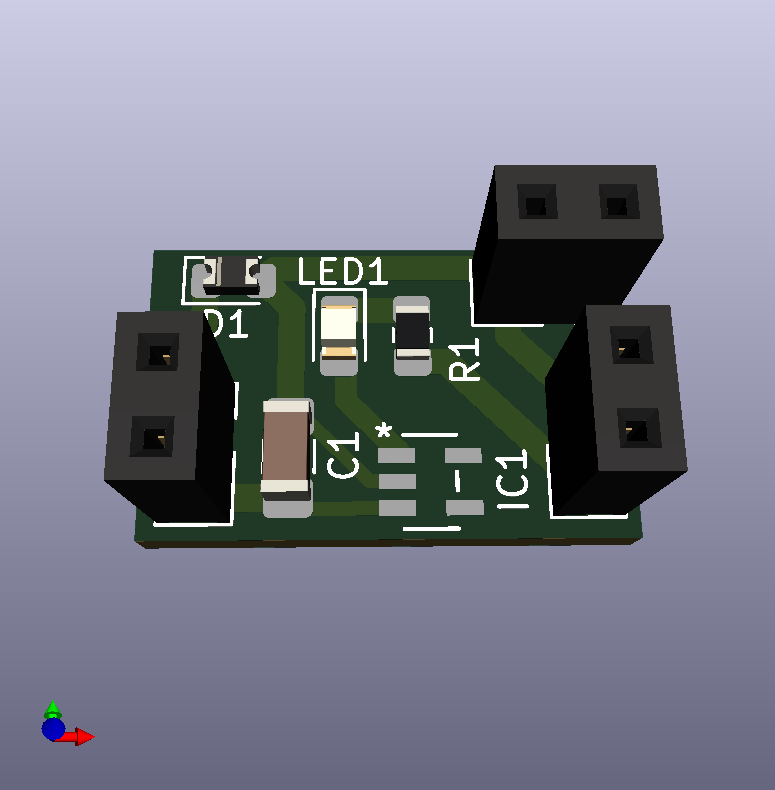
OK, I think this one's the winner: https://www.openhardware.io/dl/5b8ff8a3d376570b051a91ed/design/schematic_solarLDO_v005.pdf
It uses only 4 parts and is compatible with any input voltage: https://www.openhardware.io/dl/5b8ff8a3d376570b051a91ed/design/schematic_solarLDO_v005.pdf Thus you can stack as many or as few solar cells in series as you want to, and the circuit should work the same regardless.
How it works: current from the solar cell/panel flows through the diode to charge a capacitor (either surface mounted to the PCB or attached to the PCB using the provided through-holes). When the voltage reaches 2.7v, the voltage detector goes high, burning off 50ma of current through the 56 ohm resistor until the voltage drops below its hysteresis point. As long as the solar cell/panel's current does not exceed 50ma, this design should work. If you need to handle an input current of greater than 50ma, then simply modify the circuit to instead connect the voltage detector output to an appropriately sized mosfet for that current, and then use that mosfet to dissipate the surplus current through a suitable resistor to ground.
In my case I'm be choosing a diode with a maximum of 100na reverse current leakage, but you can choose whatever diode you want to fit your particular trade-offs.
I presume that by choosing a different voltage detector you could just as easily charge a battery instead of a supercap, if that's what you wanted to do.
-
I just now sent the files to fabrication. If it tests out as expected, then I'll post the gerber files.
-
Just for fun I added an LED that will flash each time the capacitor discharges a little to stay within its maximum 2.7v. Although brief, it indicates that solar harvesting is working and that the capacitor is fully charged.
BTW, I found a voltage detector that consumes just 150na, so I'll probably switch to using that because it will be important for the nextgen version which prioritizes the charging of a bootstrap cap before dumping solar charge into a much larger supercap.