💬 rayBeacon: nRF52 on-the-go Development Kit
-
Hi,
I'm pleased to announce that the first major release of the Raybeacon DK is out. The revision 1.0 offers all the mentioned features and can now be ordered from your favorite PCB service. For highlights please take a look to the OpenHardware description, for details (and sources) please visit the Raybeacon project page.
I've published project BoM on the Octopart where you may easily estimate components. Please note, the aQFN73 package may push you to higher PCB production line. In particular, it suggests ENIG finish and also requires 5 mil track width / clearance, so expect increase in production costs. At the same time I've tried to keep design of the extension slices at the most affordable price so it should be easy to get 10 for $5 and have some DIY fun during Xmas holidays.
The project still work in progress. Such, the radio was tuned for the nRF52840. The nRF52833 may work just fine or may be out of tune. I'm going to order several boards with 833 for that purpose, but it may take a while so please use 833 at your own risk.
And, of course, please don't hesitate to share your feedback, it will be highly appreciated!
-
And in less than a week please meet the revision 1.1.
This release addresses annoying NFC bug introduced in rev. 1.0. Such, to cleanup schematic I've moved NFC capacitors to a dedicated space where the C18 was turned upside down in order to improve text readability. This led to C18 net changes which were overlooked for the PCB. After zone refill it resulted in tying the GPIO_P0.10/NFC2 to the ground thus making the whole NFC antenna defunct.
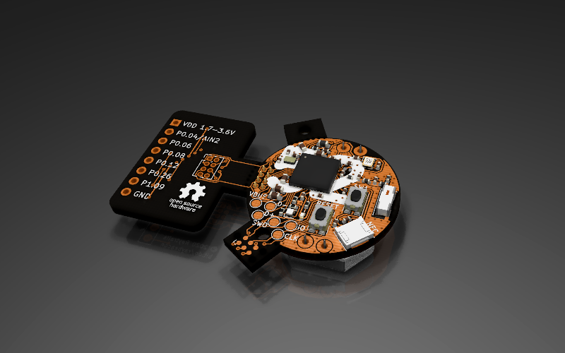
From the good, this revision adds highly requested mounting hole to the main board:

Have a nice time!
-
A little update. The nRF52833 test boards assembly was just finished. Now waiting for delivery.
@Mishka said in 💬 Raybeacon: nRF52 on-the-go Development Kit:
A little update. The nRF52833 test boards assembly was just finished. Now waiting for delivery.
Hello, who do you use to make the assembly ? Most PCB sellers who also do assembly have suspended the service at the moment.
-
@Mishka said in 💬 Raybeacon: nRF52 on-the-go Development Kit:
A little update. The nRF52833 test boards assembly was just finished. Now waiting for delivery.
Hello, who do you use to make the assembly ? Most PCB sellers who also do assembly have suspended the service at the moment.
-
@Mishka said in 💬 Raybeacon: nRF52 on-the-go Development Kit:
A little update. The nRF52833 test boards assembly was just finished. Now waiting for delivery.
Hello, who do you use to make the assembly ? Most PCB sellers who also do assembly have suspended the service at the moment.
Assembly completed. Please see updated photos on the project page!
-
Hi guys, FYI the revision 1.2 just came out.
After using the board for a while some non-critical fixes were introduced. To mention few:
- The RGB LED got color and current optimizations. It's also recommended to stick to green or blue to minimize current consumption.
- The breadboard adapter was inconvenient to cut-off and now fixed with a less fancy outline.
- The board got AEC-Q200 qualified 32768Hz crystal.
There are still some items on my TODO list (in particular, I'm not too happy about the extension socket - it can do more, and I'm going to address that separately), but the board is quite handy and definitely works. For this reason I think it's time to reset the W.I.P. bit and call the project stable.
-
The revision 1.3 is here! It adds hardware RESET feature to the SW2 push button, as well as to the SWD port. Not a big deal when attached to debugger, but so handy on the go.
Please note, the change make break your firmware because SW2 was mapped to P1.02 GPIO and now linked to the P0.18 / RESET.
-
So, while here I've decided to close my TODO list. The revision 1.4 is likely to be the last chapter in this design, and now it can be considered safe to order. It introduces some important final touches to the board, in particular:
-
The orientation key (diameter 2.1mm) on the board edge. It's located between the Tag-Connect and the board main area, and initially can be used as an eyelet. After the Tag-Connect removal it works as an orientation key for the board.
-
Full rework of the silk layer. Just to mention few: I hid all designators and decorated the board with eye catchy "52" over the nRF52 MCU, touched the antenna outline, and moved the git hash to the mainland.
-
Review and cleanup the ground plane. The changes were tiny so it shouldn't detune the antenna, but aesthetics were definitely improved. You may also want to order the board in Afterdark colors now:
Have fun!
-
-
So, while here I've decided to close my TODO list. The revision 1.4 is likely to be the last chapter in this design, and now it can be considered safe to order. It introduces some important final touches to the board, in particular:
-
The orientation key (diameter 2.1mm) on the board edge. It's located between the Tag-Connect and the board main area, and initially can be used as an eyelet. After the Tag-Connect removal it works as an orientation key for the board.
-
Full rework of the silk layer. Just to mention few: I hid all designators and decorated the board with eye catchy "52" over the nRF52 MCU, touched the antenna outline, and moved the git hash to the mainland.
-
Review and cleanup the ground plane. The changes were tiny so it shouldn't detune the antenna, but aesthetics were definitely improved. You may also want to order the board in Afterdark colors now:
Have fun!
@Mishka Very nice work indeed. One question though: I don't see an antenna of any kind built into the PCB. Maybe I'm just not seeing it, or is there none? I do see a connection for an off-board near field antenna, but off-hand I don't see where the antenna is for 2.4Ghz RF.Oh, I see it now. You're using a chip antenna. Got it.
Well, now that you've been using it for a while, how is the Raybeacon working out for you?
-