💬 The Harvester: ultimate power supply for the Raybeacon DK
-
I switched to a deadbug build using an MCP6S22 opamp for a buffer because I was getting too much conductance/noise on a pCB with the other op amp. Everything has to be soldered together, because otherwise current gets lost through the connectors when dealing with such miniscule currents.
Having done that, for the keychain solar cell I measured open circuit voltage at 2.66v at 1 lux (according to my lux meter that I mentioned above, so take that measurement for whatever it's worth) and a short-circuit current of 88na, according to a uCurrent Gold (but with the voltage measuring opamp circuit still soldered into place).
This has me wondering now how much of a voltage (non-boosted) it could eventually generate onto a capacitor, so I suppose that's the next thing to try. I'll try it first with my simple solar charger: https://www.openhardware.io/view/620/Supercap-solar-charger
since that's easy, but for a more accurate measurement I may need to construct a deadbug equivalent using just a diode and capacitor. That would be a lower bound for the dead simple approach which then perhaps some harvester could improve upon, though I'm not sure any of the commercial energy harvesters are spec'd at that low of a power.This also explains why measuring the voltage of the solar cell with just a volt meter (with no op amp circuit to help it) is hopeless at such low light levels: 2.66v divided by 10MOhm is 266 nanoamps, where 10MOhm is the typical digital volt meter input resistance. i.e. the 266 nanoamps drain through the volt meter would be approximately 3x the amount of current that the solar cell can generate, thereby causing a large error in the voltage measured by the DMM.
Edit2: I connected a 100uF ceramic capacitor in parallel with the solar cell (I didn't bother with adding a diode), and it charged up to 2.778v. Somehow that's slightly higher than the previously measured open circuit voltage of 2.66v. Not sure how that is, but perhaps the orientation of the solar cell was a little more favorable when this measurement was taken. In any case, I think whatever the open circuit voltage is, you can probably charge up to that amount with any size low leakage capacitor that you want to use. :grinning: So, from this point of view, choosing a solar cell which generates high open circuit voltages in very dim light is perhaps more important than any other decision if what you want is something that can get past startup even if the available power is only minuscule.
The only thing needed is a simple control circuit which, if possible, consumes little or no energy until it reaches the desired voltage range, whereupon a more sophisticated control circuit can take over. Something like a schmitt trigger might work, but it would need to draw extremely little current, which not all schmitt triggers do, especially as they approach the threshold voltage. Any ideas?
Perhaps something like: https://hackaday.com/2018/07/19/energy-harvesting-design-doesnt-need-sleep/
or perhaps a solar engine control circuit might work: http://beambuilder.blogspot.com/p/solar-engines.html
or...???
Since they all do more or less the same thing (charging a capacitor to a threshhold voltage and then "turning on"), the challenge would be to find (or invent) a circuit which achieves that result but while consuming the absolute least amount of power that current technology allows. A lot of the published designs use older technology, and so I suspect better possibilities exist if leveraging newer, more capable components. -
I switched to a deadbug build using an MCP6S22 opamp for a buffer because I was getting too much conductance/noise on a pCB with the other op amp. Everything has to be soldered together, because otherwise current gets lost through the connectors when dealing with such miniscule currents.
Having done that, for the keychain solar cell I measured open circuit voltage at 2.66v at 1 lux (according to my lux meter that I mentioned above, so take that measurement for whatever it's worth) and a short-circuit current of 88na, according to a uCurrent Gold (but with the voltage measuring opamp circuit still soldered into place).
This has me wondering now how much of a voltage (non-boosted) it could eventually generate onto a capacitor, so I suppose that's the next thing to try. I'll try it first with my simple solar charger: https://www.openhardware.io/view/620/Supercap-solar-charger
since that's easy, but for a more accurate measurement I may need to construct a deadbug equivalent using just a diode and capacitor. That would be a lower bound for the dead simple approach which then perhaps some harvester could improve upon, though I'm not sure any of the commercial energy harvesters are spec'd at that low of a power.This also explains why measuring the voltage of the solar cell with just a volt meter (with no op amp circuit to help it) is hopeless at such low light levels: 2.66v divided by 10MOhm is 266 nanoamps, where 10MOhm is the typical digital volt meter input resistance. i.e. the 266 nanoamps drain through the volt meter would be approximately 3x the amount of current that the solar cell can generate, thereby causing a large error in the voltage measured by the DMM.
Edit2: I connected a 100uF ceramic capacitor in parallel with the solar cell (I didn't bother with adding a diode), and it charged up to 2.778v. Somehow that's slightly higher than the previously measured open circuit voltage of 2.66v. Not sure how that is, but perhaps the orientation of the solar cell was a little more favorable when this measurement was taken. In any case, I think whatever the open circuit voltage is, you can probably charge up to that amount with any size low leakage capacitor that you want to use. :grinning: So, from this point of view, choosing a solar cell which generates high open circuit voltages in very dim light is perhaps more important than any other decision if what you want is something that can get past startup even if the available power is only minuscule.
The only thing needed is a simple control circuit which, if possible, consumes little or no energy until it reaches the desired voltage range, whereupon a more sophisticated control circuit can take over. Something like a schmitt trigger might work, but it would need to draw extremely little current, which not all schmitt triggers do, especially as they approach the threshold voltage. Any ideas?
Perhaps something like: https://hackaday.com/2018/07/19/energy-harvesting-design-doesnt-need-sleep/
or perhaps a solar engine control circuit might work: http://beambuilder.blogspot.com/p/solar-engines.html
or...???
Since they all do more or less the same thing (charging a capacitor to a threshhold voltage and then "turning on"), the challenge would be to find (or invent) a circuit which achieves that result but while consuming the absolute least amount of power that current technology allows. A lot of the published designs use older technology, and so I suspect better possibilities exist if leveraging newer, more capable components.@NeverDie Wow, I'm really surprised with so high voltage of the panel. Thank you for sharing the measurements!
My understanding is that OC voltage is defined by amount of free electrons in the depletion zone, and hence by the width of the zone. When in the light, more electrons will fill the zone, but there seem to be some saturation threshold limiting the max voltage. It would be interesting to somehow measure the electric field in the full absence of light. Also, capability to emit new electrons in the depletion zone defines the max current from the cell. It looks like crystalline cells can do it more effectively than amorphous, but the latter have wider depletion zone in the dark.
I don't know how to use so ultra-low current sources. The harvester should be able to work from 100 nanoamps or below. This limits design to a linear charger only (at least at frontend) - anything more complex (like a boost or buck circuit) would require higher quiescent current which will collapse the cell.
A MOSFET may draw as low as few nanoamps so virtually it could be possible. The PV cell needs to be isolated from the load to prevent voltage drop on the FET which may cause it defunct. Perhaps an isolated capacitor will be required to sustain the FET state while input capacitor releases its charge. The FETs may require resistors to shift voltage level, but again, they need to be hundreds of megohm. This will also impact switching speed. Perhaps some sort of hiccup switching circuit may make it. Also, I see some similarities with how dynamic RAM implemented.
For a usual solution, there are some ideal diode like the MAX40203 with 300 nA quiescent current. I suspect that the charge pump of the SM74611 may draw microamps when in ON state - it's unclear from the datasheet.
All in all, it looks like a puzzle :-)
-
If you're able to run in some kind of duty cycled mode, where the control circuitry is only active for brief periods of time, then perhaps the quiescent currents get averaged down to a more manageable level. As a first step, I think I'll just blithely assume the control circuitry can access at least some conventional voltage levels (either saved up from earlier energy harvesting or else gathered in a crude way like in my example above). If I can make good progress doing that, then I can always revisit that assumption at a future date.
-
TPL5100, which draws just 30na, looks promising for duty cycling the control circuitry:
http://www.ti.com/lit/ds/symlink/tpl5100.pdf
It has both a PGOOD pin as well as a mosfet driver pin. The edge case would need confirming that it can slowly power up from zero volts to its minimum 1.8v operating voltage with only just over 30na source current without itself drawing more than 30na. Since it has a PGOOD pin, I'd wager that it's unlikely to emit false positive signals while still charging at below 1.8v, because if it did the PGOOD pin would be worthless. :thinking_face: -
Found a nice paper on charge pumps design: https://www.mdpi.com/2079-9292/8/5/480.
@Mishka said in 💬 The Harvester: ultimate power supply for the Raybeacon DK:
Found a nice paper on charge pumps design: https://www.mdpi.com/2079-9292/8/5/480.
@Mishka I read a similar paper (http://citeseerx.ist.psu.edu/viewdoc/download;jsessionid=D650012CC6F5208E02BF41AE55DF0E95?doi=10.1.1.128.4085&rep=rep1&type=pdf) which says that the best charge pumps use static charge transfer switches. That said, I'd be happy if I could build any kind of ultra low energy harvesting charge pump using discrete components as long as the component count is low.
-
I tried it with a TPL5110 just now, but it gets caught in a boot loop: voltage rises to 1.440v and then suddenly drops to about 1.400v. I think this is because when the TPL5110 starts up for the first time, it draws ~200ua current to read the resistor settings, which it then stores and uses for the time delay.
So, if there exists a similarly low current timer that can be set without a heavy drain step like that just described, then I'd go for that instead.Meanwhile, this is the lowest current (88na) voltage detector that I know of: https://www.torex-usa.com/products/voltage-supervisors/low-power/xc6136/
That would limit me to light sources something greater than 1 lux (as measured by my lux meter) if I am to harvest anything using the brute force simple approach for a cold start, but once I get enough of a power reserve I could maybe harvest lesser amounts by duty cycling something like an LTC3108. -
@NeverDie Maybe try to bootstrap it with external voltage source applied parallel to the cell?
@Mishka said in 💬 The Harvester: ultimate power supply for the Raybeacon DK:
@NeverDie Maybe try to bootstrap it with external voltage source applied parallel to the cell?
I'm not sure what that would look like. Do you have anything concrete in mind?
-
@Mishka said in 💬 The Harvester: ultimate power supply for the Raybeacon DK:
@NeverDie Maybe try to bootstrap it with external voltage source applied parallel to the cell?
I'm not sure what that would look like. Do you have anything concrete in mind?
-
@Mishka said in 💬 The Harvester: ultimate power supply for the Raybeacon DK:
@NeverDie So when TPL5110 has passed the boot phase does it work after that?
Ah, good question. Then it seems to work just fine. I had it waking once every 10 seconds and weakly flashing an amber LED, all on just 88na of collected solar current. Essentially, the capacitor voltage would drop to just below the forward voltage of the LED during the flash (effectively self terminating the flash duration) and then it would charge back up from there.
@NeverDie Oh, nice! It's interesting that the full circle including oscillator consumes so low power. It seems really possible to build a discrete harvesting circuit which can collect enough charge to execute a single duty cycle of an MCU.
Such, assuming (88-35) nA/s = 53 nC charge it will require less than 5 minutes and 22 µF capacitor in order to shot a single BLE event from an nRF52 MCU. And that's at so ridiculous low light. Quite awesome, I think.
The only issue is that the timer can't optimize it for faster charge, but a voltage driven latch could.
-
@NeverDie Oh, nice! It's interesting that the full circle including oscillator consumes so low power. It seems really possible to build a discrete harvesting circuit which can collect enough charge to execute a single duty cycle of an MCU.
Such, assuming (88-35) nA/s = 53 nC charge it will require less than 5 minutes and 22 µF capacitor in order to shot a single BLE event from an nRF52 MCU. And that's at so ridiculous low light. Quite awesome, I think.
The only issue is that the timer can't optimize it for faster charge, but a voltage driven latch could.
@Mishka Just FYI, in my experiment I drove the LED directly from the DRV pin (I didn't use a MOSFET), and I didn't bother with setting the DONE pin, since I wasn't using a MCU. That gave a maximum possible flash duration of 50ms once every 10 seconds, but like I said, it self-terminated before the full 50ms was up because the capacitor voltage dropped below the forward voltage of the LED. Using a mosfet and an MCU, as intended, would give a little more control, since the the MCU could issue a DONE signal.
So, yeah, it really is impressive what can be done with so little light, and it could actually go with even less light and a longer charge time, provided the startup hurdle can be gotten past.
Unfortunately, the XC6136 doesn't yet seem to be widely available at the the all the different possible voltages that can be detected. Digikey doesn't have any, and mouser has only just 3 different types. Perhaps that will improve in the future.
So, perhaps this is a case where powering the TPL5110 from a primary cell would be an acceptable "cheat". At just 35na, that primary cell should last a very long time.
-
I received a 0.02% accurate 500,000 count DMM that should make measuring changes by small voltage and current amounts a bit easier:
If you're in the market for such a thing, now is a good time to buy, as prices are lower than I have ever seen before and a number of the models previously available from Extech, Brymen, GreenLee, AmProbe and other labels have been discontinued (permanently, it would seem). The models still in production cost 2-3x as much, as did the discontinued models up until fairly recently.
Interestingly, in the dead of night the keychain solar cell can nonetheless pull down 1.3v from a window facing a streetlight that's across the street, as measured with the op amp buffer using a DMM. That amount of light is so low that it registers as 0.2 lux on my lux meter. On the other hand, it also measures 0.2 lux even with the lens cover on, so I think it's below my lux meter's ability to measure it, as the 0.2 lux appears to be just an offset that should be calibrated to zero.
An alternative to the opamp buffer would be to have the solar cell charge a 0.1uF capacitor, which then gets quickly read by an arduino ADC. I haven't wired that up yet, but I expect the results would be about the same.
Or, you could charge a larger capacitor for a longer period of time and perhaps try to snag it with a peak voltage reading when you first connect to it with your DMM. I haven't tried this. I expect it would work, at least to some degree, if you used a big enough capacitor and charged it for long enough, so it might be worthwhile if you have lots of patience.
Interestingly, the typical input resistance for an oscilliscope is only 1 MegaOhm. For a typical DMM, it's 10 MegaOhm, and for an atmega328p ADC, it's 100 MegaOhm. Thus, if measuring 5 volts, the Arduino ADC would experience a 50 nanoOhm drain. That's too high for measuring weakly sourced solar voltages under very dim lighting. 10 gigaohm would be preferable, but then it will take some time to charge up an input capacitor for the ADC to read.
It would be better to leave the input impedance as is but use software to disconnect the input pin when it's not being used. That's certainly possible with an nRF5x, but I'm not aware of that being possible on an Arduino Uno. Is it?
I could connect/disconnect it with a mosfet or a transistor, but then we're back to supplementing the arduino uno with more hardware again, and the voltage drop across such hardware needs to be adjusted for, since the whole point is to get an accurate voltage measurement.
@NeverDie said in 💬 The Harvester: ultimate power supply for the Raybeacon DK:
Interestingly, in the dead of night the keychain solar cell can nonetheless pull down 1.3v from a window facing a streetlight that's across the street, as measured with the op amp buffer using a DMM. That amount of light is so low that it registers as 0.2 lux on my lux meter.
It would be interesting to measure voltage when the panel is dead black. Should be possible by wrapping it into paper and then aluminum foil. In theory it should be perfect zero, but connecting wires and the cell itself may work as antenna and hence the opamp may show some bias.
An alternative to the opamp buffer would be to have the solar cell charge a 0.1uF capacitor, which then gets quickly read by an arduino ADC. I haven't wired that up yet, but I expect the results would be about the same.
Yeah, the charge capacitor is part of some ADC implementations. But instead of use of comparators it might be possible to measure charge / discharge time and derive current and voltage from that. Also, knowing the charge current it will be easy to derive time to full charge and select proper capacitor.
It would be better to leave the input impedance as is but use software to disconnect the input pin when it's not being used. That's certainly possible with an nRF5x, but I'm not aware of that being possible on an Arduino Uno. Is it?
From my understanding, input impedance of most of MCU ADC pins (when disabled) are defined by MOSFETs and hence is subject to implementation and input voltage. But with the charge capacitor large enough it should be not an issue, at least as long as the capacitor wasn't connected to the ADC port during the charge (otherwise the impedance must be gigohms in order to be negligible small). Perhaps a mechanical switch could better solve it for the task. And then MCU can be used to measure time to discharge and do the math.
Also, I must note that to charge the capacitor with tens of nanoamps, the harvester control circuit must consume something in picoamps :-) And this makes me think that, first, there must be a reasonable bottom limit, and, second, a combined RF / solar harvester may be an interesting option to go, especially taking in account they can be connected to the same input.
-
@NeverDie said in 💬 The Harvester: ultimate power supply for the Raybeacon DK:
Interestingly, in the dead of night the keychain solar cell can nonetheless pull down 1.3v from a window facing a streetlight that's across the street, as measured with the op amp buffer using a DMM. That amount of light is so low that it registers as 0.2 lux on my lux meter.
It would be interesting to measure voltage when the panel is dead black. Should be possible by wrapping it into paper and then aluminum foil. In theory it should be perfect zero, but connecting wires and the cell itself may work as antenna and hence the opamp may show some bias.
An alternative to the opamp buffer would be to have the solar cell charge a 0.1uF capacitor, which then gets quickly read by an arduino ADC. I haven't wired that up yet, but I expect the results would be about the same.
Yeah, the charge capacitor is part of some ADC implementations. But instead of use of comparators it might be possible to measure charge / discharge time and derive current and voltage from that. Also, knowing the charge current it will be easy to derive time to full charge and select proper capacitor.
It would be better to leave the input impedance as is but use software to disconnect the input pin when it's not being used. That's certainly possible with an nRF5x, but I'm not aware of that being possible on an Arduino Uno. Is it?
From my understanding, input impedance of most of MCU ADC pins (when disabled) are defined by MOSFETs and hence is subject to implementation and input voltage. But with the charge capacitor large enough it should be not an issue, at least as long as the capacitor wasn't connected to the ADC port during the charge (otherwise the impedance must be gigohms in order to be negligible small). Perhaps a mechanical switch could better solve it for the task. And then MCU can be used to measure time to discharge and do the math.
Also, I must note that to charge the capacitor with tens of nanoamps, the harvester control circuit must consume something in picoamps :-) And this makes me think that, first, there must be a reasonable bottom limit, and, second, a combined RF / solar harvester may be an interesting option to go, especially taking in account they can be connected to the same input.
@Mishka said in 💬 The Harvester: ultimate power supply for the Raybeacon DK:
It would be interesting to measure voltage when the panel is dead black. Should be possible by wrapping it into paper and then aluminum foil. In theory it should be perfect zero, but connecting wires and the cell itself may work as antenna and hence the opamp may show some bias.
OK, I'll try it and let you know.
@Mishka said in 💬 The Harvester: ultimate power supply for the Raybeacon DK:
Also, I must note that to charge the capacitor with tens of nanoamps, the harvester control circuit must consume something in picoamps
You're right, there just aren't going to be any control circuits that run on mere pico-amps on a continuous basis, and that sets the limit on how low you can go. It's for that very reason that I'm hoping to find some kind of ultra low current, very low frequency, low voltage self starting circuit that effectively draws almost no current until it starts up. It wouldn't have to start at a precise voltage. Just in a general ballplark. Maybe something like this, except lower voltage than 3v?
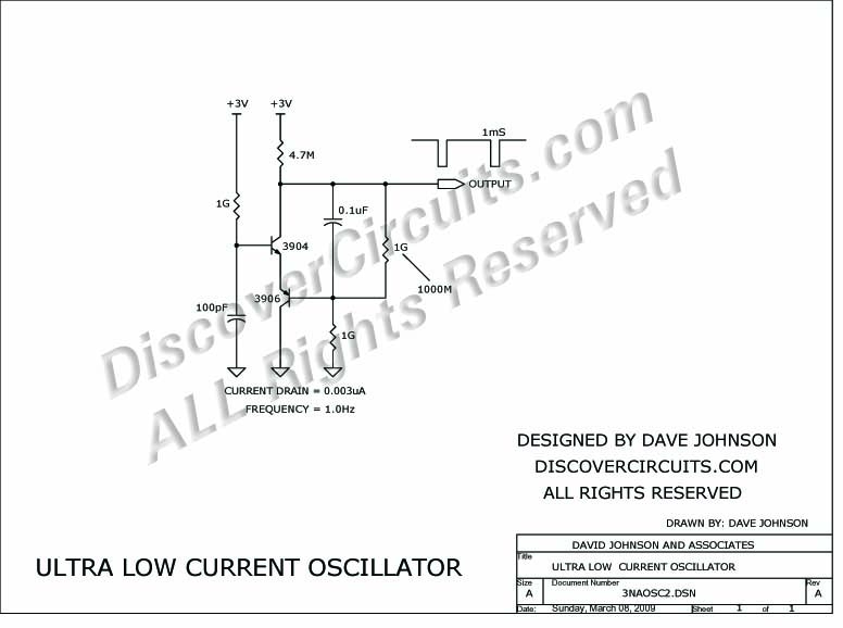
http://www.discovercircuits.com/DJ-Circuits/3na-osc.htm
Seems like it should be possible, given progress in the components since that circuit was drawn, which is now quite a while ago.If so, maybe it could even be used to drive a boost converter, similar to:

and with a high enough voltage, perhaps a voltage multiplier as well:

http://dangerousprototypes.com/blog/2013/07/20/avalanche-pulse-generator-and-some-scope-porn/Basically, the circuit needs to remain inert until enough charge builds up and a trigger gets tripped. And, it needs not to bootlooop even though it ramps up using just very little current. A tall order, I know. Not sure if the right kind of circuit exists, but that's what I'm in the hunt for.
If not a multivibrator, then maybe a ring oscillator. Or, if not that, then a blocking oscillator. And if not that, ...., who knows? There are lots of research papers published where people have been able to do it, but unfortunately a lot of them are IEEE published, and so I don't have access to the details of how it has been done. For sure, a lot of it is instantiated into a CMOS chip, which is beyond my reach anyway, but some of them do seem to use discrete components.
If you have any suggetions, I'm all ears.
-
@Mishka said in 💬 The Harvester: ultimate power supply for the Raybeacon DK:
It would be interesting to measure voltage when the panel is dead black. Should be possible by wrapping it into paper and then aluminum foil. In theory it should be perfect zero, but connecting wires and the cell itself may work as antenna and hence the opamp may show some bias.
OK, I'll try it and let you know.
@Mishka said in 💬 The Harvester: ultimate power supply for the Raybeacon DK:
Also, I must note that to charge the capacitor with tens of nanoamps, the harvester control circuit must consume something in picoamps
You're right, there just aren't going to be any control circuits that run on mere pico-amps on a continuous basis, and that sets the limit on how low you can go. It's for that very reason that I'm hoping to find some kind of ultra low current, very low frequency, low voltage self starting circuit that effectively draws almost no current until it starts up. It wouldn't have to start at a precise voltage. Just in a general ballplark. Maybe something like this, except lower voltage than 3v?
http://www.discovercircuits.com/DJ-Circuits/3na-osc.htm
Seems like it should be possible, given progress in the components since that circuit was drawn, which is now quite a while ago.If so, maybe it could even be used to drive a boost converter, similar to:
and with a high enough voltage, perhaps a voltage multiplier as well:
http://dangerousprototypes.com/blog/2013/07/20/avalanche-pulse-generator-and-some-scope-porn/Basically, the circuit needs to remain inert until enough charge builds up and a trigger gets tripped. And, it needs not to bootlooop even though it ramps up using just very little current. A tall order, I know. Not sure if the right kind of circuit exists, but that's what I'm in the hunt for.
If not a multivibrator, then maybe a ring oscillator. Or, if not that, then a blocking oscillator. And if not that, ...., who knows? There are lots of research papers published where people have been able to do it, but unfortunately a lot of them are IEEE published, and so I don't have access to the details of how it has been done. For sure, a lot of it is instantiated into a CMOS chip, which is beyond my reach anyway, but some of them do seem to use discrete components.
If you have any suggetions, I'm all ears.
@NeverDie said in 💬 The Harvester: ultimate power supply for the Raybeacon DK:
@Mishka said in The Harvester: ultimate power supply for the Raybeacon DK:
It would be interesting to measure voltage when the panel is dead black. Should be possible by wrapping it into paper and then aluminum foil. In theory it should be perfect zero, but connecting wires and the cell itself may work as antenna and hence the opamp may show some bias.
OK, I'll try it and let you know.
@Mishka 8mv was as low as I could take it, but I suspect even then there may have been some slight amount of light getting at it. The room was very dark, but I could make out shapes with night vision, and the backlight on my Fluke 87v was leaking light all over the place, even though I tried to shield it. To really do it properly I'd probably have to set up a wireless link so that I could be in another room to read the voltage. Either that or set up a logger and check it after-the-fact. So, summarizing, I apologize I didn't do a more thorough job, but for being conducted in the middle of a pandemic I did the best that time allows, and besides, 8mv is pretty close to zero, so I hope that answers your question well enough. :) As a cross-check to rule out the possibility of it being an artifact, I'll sometime soon take the measurement in a brief snapshot using an arduino, without the aid of an op-amp, and see how that compares. I'll probably use a load switch to disconnect the arduino so that the solar cell has a chance to charge up a capacitor between readings, and I anticipate that given enough time it will eventually charge up to the open circuit voltage.
Should I start a separate thread for this, or continue it here? It seems that your project is completed, and although this is all relevant, maybe it would be better to split it off? @Mishka Since you're the OP, what's your preference? Continue as is, or fork your thread and continue in a separate thread? I'm enjoying the collaboration, and hope you feel the same. I'm fine with either choice.
-
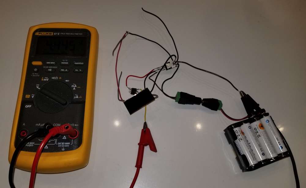
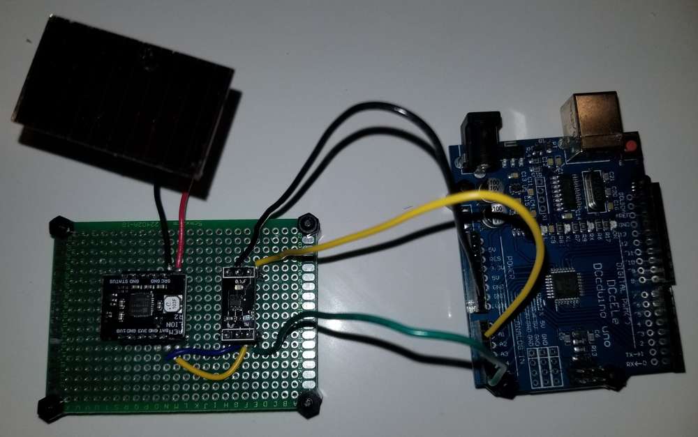
In case anyone is curious, this is the dead-bug setup I used to do the op-amp assisted measurements:
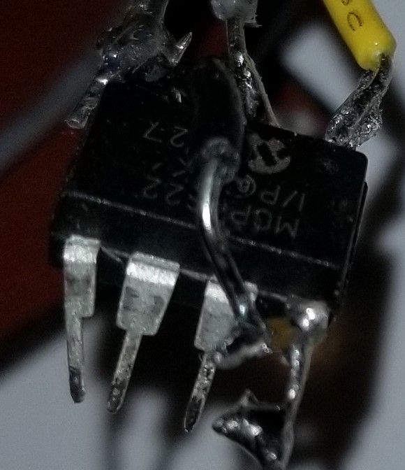
The op-amp calls for a bypass capacitor to be soldered within one millimeter of the input signal, so I soldered a small surface mount ceramic cap directly to that pin and then ran a wire to it from the GND pin. Not sure how well you can see it, but here's a photo of that:
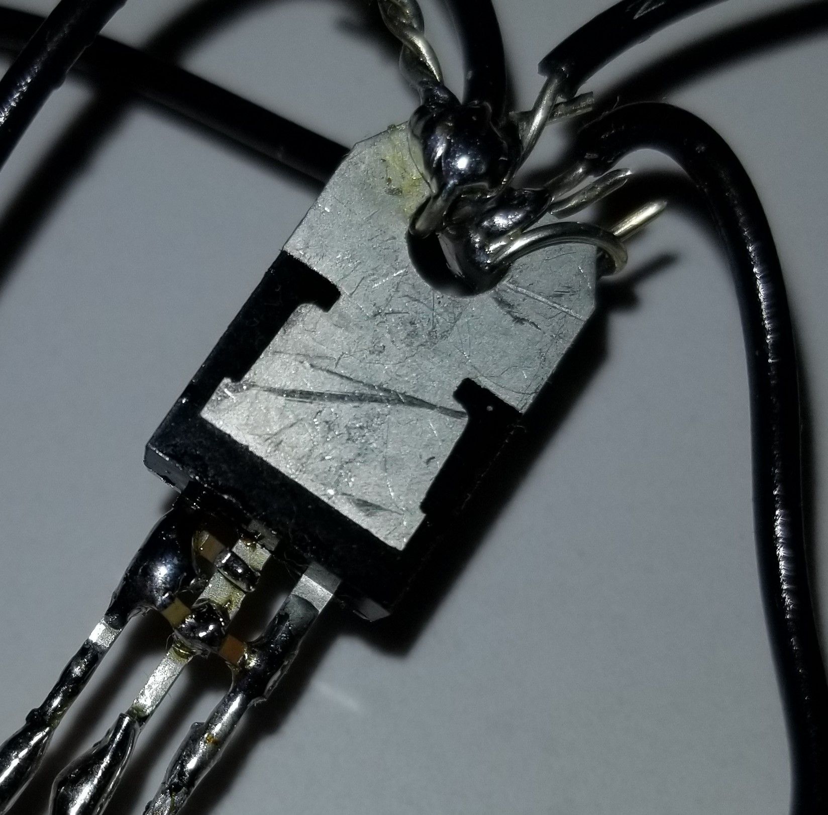
The LDO had similar capacitor requirements, and I was able to solder those directly between its pins:
Maybe because of that, despite all the long wires, noise didn't seem to be a problem. The reason for the deadbug design and the DIP op-amp was to avoid any leakage currents that might happen if it were all mounted properly to a protoboard, as I've read accounts from others who have tried doing that but who ran into leakage problems.
So, while I admit it looks awfully scruffy, it doesn't matter, because it's purpose built just to help get accurate open circuit voltage measurements (and short-circuit current measurements with a uCurrent Gold, not shown here).
-
And here is Version 2, which uses an Arduino UNO to and a load switch to measure an E-PEAS solar module that's charging a 100uF capacitor using a solar keychain solar cell. This time I did use a prototype board.
It's too soon to evaluate, but it seems as though it's off to a good start....Edit: nope. I'll have to migrate the Arduino design to dead-bug, because the voltage is only very slowly crawling up. Maybe that's just how it is with this the E-PEAS, or else maybe mounting leakage (the higher the voltage the higher the leakage) is what's causing the drag.
Edit2: confirmed. These measurements were taken at 1 minute intervals, under varying cloud conditions, and it's clearly not able to hold on to the charge the E-PEAS has accumulated on the 100uF ceramic cap:
734, raw = 652, volts = 3.267 735, raw = 689, volts = 3.453 736, raw = 371, volts = 1.859 737, raw = 399, volts = 1.999 738, raw = 445, volts = 2.230 739, raw = 556, volts = 2.786 740, raw = 616, volts = 3.087 741, raw = 671, volts = 3.362 742, raw = 371, volts = 1.859 743, raw = 444, volts = 2.225 744, raw = 510, volts = 2.556 -
I punted on the Arduino and hooked up the E-Peas AEM10941 module to the deadbug op-amp for measurement, as the dead-bug op-amp appears to work flawlessly. The results were: the AEM10941 does build up to a voltage of about 4.135v max when under fairly bright lighting, and then all that disappears and it reverts to starting to charge up again from a voltage of about 1.8v, and it cycles over and over like that. Kinda weird, but that unexpected result may explain the above 1 minute interval readings: probably (?) it wasn't current leakage but instead this kind of cycling that explains the measurements.
Edit: Unfortunately, the AEM10941 breakout board can't seem to rise above 0.352 volts when tested with the same solar cell and same dead-bug op amp assembly under the same 1 flux light source, so I'm afraid I have to label it a FAIL for use in boosting, just by itself, from that particular low light scenario. Given its datasheet, I'm rather disappointed. I did clean the board and my soldered connections pretty thoroughly with IPA, but perhaps there are other leakages inherent in that board, or perhaps the chip itself has limitations that maybe aren't apparent from its datasheet.
Which raises an interesting question: are some types of PCB's less prone than others when it comes to leakage currents? It might make a difference in what kind I order from a PCB fabhouse if some types are better than others. Anyone know?
I didn't test whether the AEM10941 might have some other beneficial use if that barrier is somehow passed, or assisted in being passed, but for now I'm moving on to test some other chips and see how they perform under these conditions to see whether they perform any better and without needing help.
Edit: BQ25504 has no problem charging under the 1 lux light, under the same conditions, even from a starting voltage of zero volts.
Edit2: Well, not quite. Despite a promising start, the BQ25504 peaked at 0.812v and couldn't seem to pull itself above that. It was able to charge up further than the AEM10941, but it hit a ceiling nonetheless. So this time I gave it some bright light to bring its supercap voltage up to 0.814v, and now the voltage appears to be climbing again, al beit slowly. Assuming it is able to continue on its own from this point forward, then my theory is that internally there is a schmitt trigger which is causing this effect: as the voltage slowly rises, the current drain increases up to a peak and then declines again as the voltage continues to rise. At least that is how TI describes typical schmitt trigger behavior in Figure 1 of TI's application report entitled "Understanding Schmitt Triggers": http://www.ti.com/lit/an/scea046/scea046.pdf
Vertical axis is current and horizontal access is voltage.
So, if that peak current drain is greater than the current generated by the solar cell at the 1 lux light level, it simply can't push past it to the other side.Both chips seem rather pathetic if, as seems to be the case, a solar cell alone and without assistance can charge up a capacitor to its open circuit voltage of somewhere around 2.7v but they can't. To be fair, there could be other factors in play, though, like the PCB material type, the dialectric the manufacturer used to impregnate the FR4 to make the PCB, how much humidity had gotten into the FR4 (resulting in extra leakages), component choices as well as layout. That was my earlier hunch, but that hunch may get upended and replaced with the schmitt trigger theory if the BQ25504 continues its upward charge. We shall soon see.
Meanwhile, somewhere I have laying around a BQ25570 on a chinese breakout board, and it might (?) possibly avoid this problem that the other two seem to share....
Edit3: Nope. The BQ25504 simply got stuck again, this time at 0.851v. According to the datasheet, it's still in cold-start mode until the voltage on VSTOR reaches at least 1.6v (or possibly higher), and that matches what I recall about the BQ25504 from earlier experimentation with it: it performs pretty terribly while in cold-start mode.
Punt!
Unfortunately, BQ25570 also remains in cold start mode up to the same 1.6v+ as the BQ25504, so I'm losing optimism that it might be any better... And like the BQ25504, the BQ25570 also requires typically 15uw to get its mojo on, and at 88na of current that just isn't going to happen.
So, there's no rush to test the BQ25570. If the datasheet is right, it's almost certainly another FAIL. :( Judging from the datasheet, the BQ25570 is largely just the BQ25504 mashed together with a buck converter. And the BQ25505 looks about the same as the BQ25504, except with a little bit less quiescent current.What a disappointment! I would have thought that TI had the in-house talent to do a lot better than this.