💬 No neutral power supply/relay board for in wall switch
-
Hello,
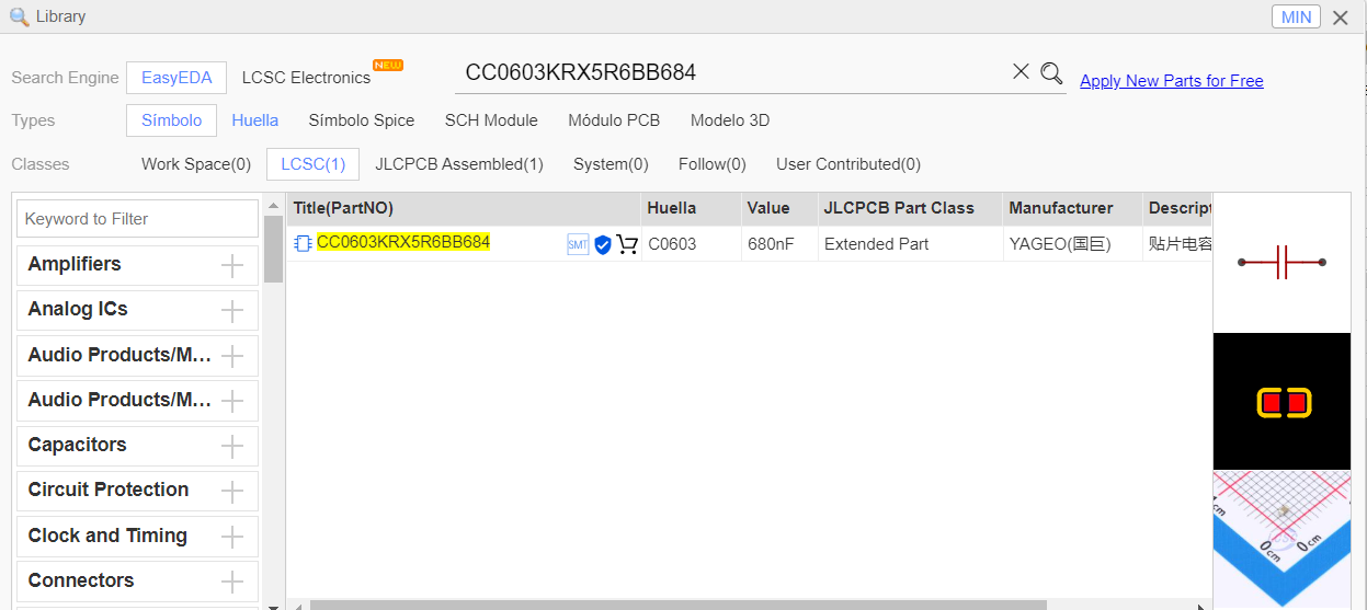
I looked for the manufaturer part of C10 in EasyEDA Library "CC0603KRX5R6BB684" and I noted that it describes a 680nF/10V capacitor, but in the schematic it is supposed to be 100nF/50V, (CC0603KRX7R9BB104), so which is correct?
 This post is deleted!
 -
The LNK364 has an internal 6.3V zener diode across BP and S so the 10V is OK, though the 50V is probably a better idea. The data sheet indicates the capacitance should be 0.1 μF (100nF). I'd recommend the latter. (It could be a typo in the EasyEDA)
-
Thanks @OldSurferDude.
I am bit newbie in circuit design, does the R20 inrush current limiting resistor must be 2W? or the 0.5W resistor in the BOM works fine?
-
I would say the 2W should be used. I say this because it would be exceptional to spec 2W and there is probably good reason to do so, though I do not know that reason.
Often times people with experience with the design reason that a different value will work. Or they find that the component doesn't mechanically fit into the modified design. (I will admit to doing this myself) I suspect that the resistor periodically is dissipating 1W (1W of tolerance). If this is the case, after many cycles, even years, the 1/2W will fail.
I will share some experience. I put 2W (12V/0.15A) into a 2W resistor. I went to pick up the board and grabbed it by the resistor and burnt the crap out of my fingers.
Overdesigning is good. Cautionary tale: Mrs. Fiorina told the printer mech designers that they make the printers too good and that they should make them cheaper. The company of which she was CEO is not doing so good today.
-
Pardon if the question is silly,
I want to use this power supply to pwer up a small mcu and some leds, but I don not know if I could draw less than what one of the notes says: "The touch sensing board including radio/mcu must not draw more than 8-10mA on average" why is that?
-
My guess is that the the leakage power captured can only supply that amount of current (at the specified voltage)