Finally, progress! (evidence based radio testing method) (and capacitors)
-
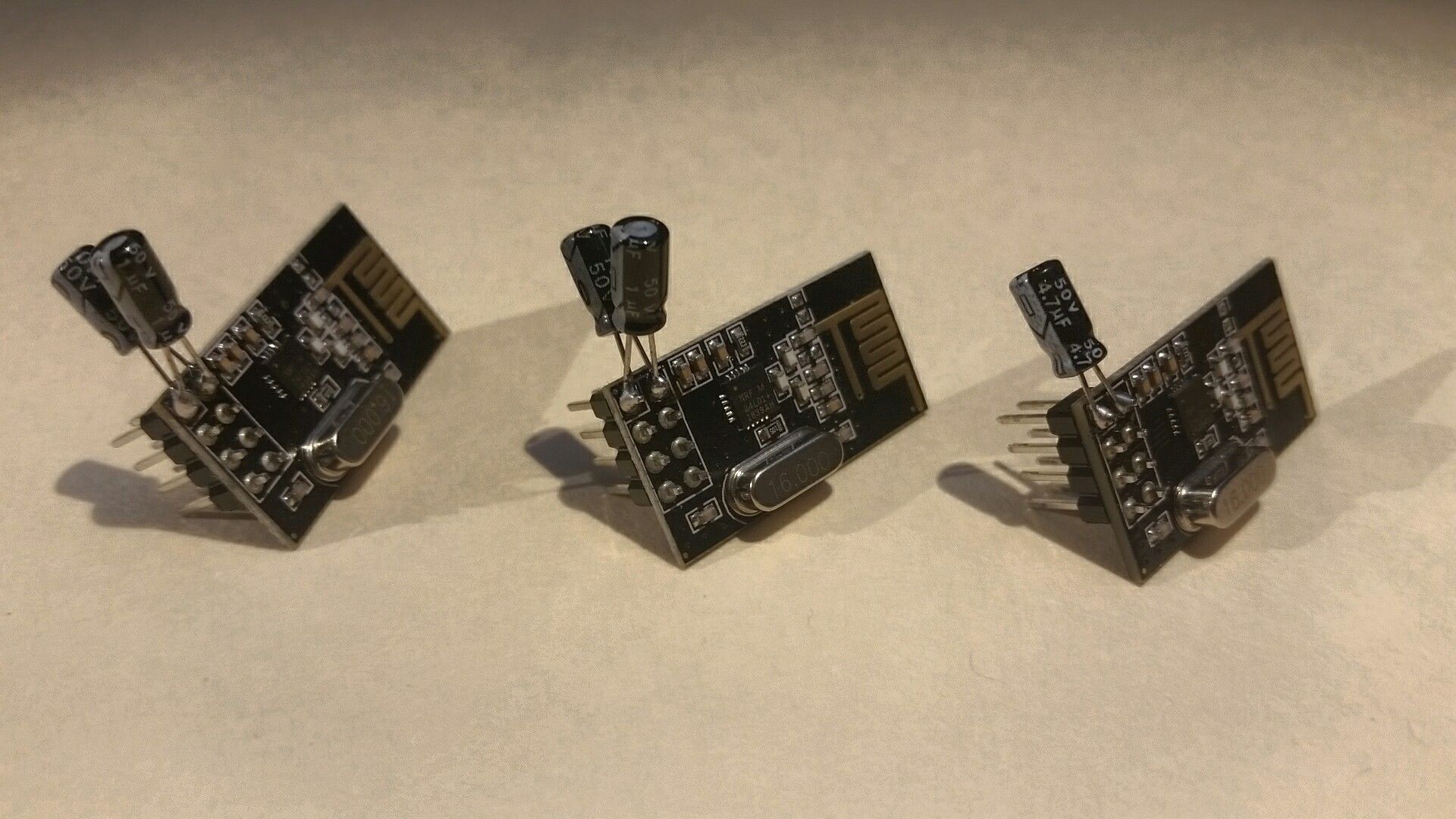
I wanted to test my theory that two different value capacitors in parallel was somehow better than one of a similar capacity. So with everything exactly the same as I had left it last night, I soldered up two new radios, except this time with only a single 10uF electrolytic 50v capacitor, instead of 1uF + 10uF.
Results can be found in "test 10" above. Looks slightly less reliable at 96.48% than test 8 which was 100%!
Now, I am not going to the trouble of using the exact same radios, desoldering components, etc... I suppose there is a chance that some of these radios might be "better" in some way than others. They did all come from the same batch at least, FWIW...
Perhaps one of you professional angry pixie wranglers out there can verify that there is in fact something to the "two capacitors of different values in parallel" theory?
But for me, this is a dramatic improvement over what I was getting before (test 7 being closest approximation), so I think I will get back to building a new gateway and some new nodes, putting to work some of the things I have learned here.
Cheers! :beers:
-
Nice work. I took the liberty to reformat the table into markdown, which is easier to view in the forum.
TN SL RL STC SC SCL RTC RC RCL LR LT R % ARTD N 1 1 1 1,3,4 1 12 2 1 21 878 906 96.91 28.16 2 " 2 " " " " " " 3 " " " 2 " " 2 " 801 1016 78.84 25.75 1 4 " 3 " " " " " " 910 959 94.89 23.68 5 " 4 " " " " " " 853 946 90.17 25.22 6 6 " " " " " " " 871 875 99.54 23.73 2 7 " 5 " " " " " " 28 289 9.69 40.39 8 " 7 " " " " " " 684 684 100.00 22.91 3 9 " " " 1 " " 1 " 600 1042 57.58 34.47 10 " " " 3 " " 3 " 1014 1051 96.48 24.58 11 -
It's great to see that you are putting in the effort to thorougly test and optimize your setup. I like that! :+1:
Now, I'm also not an EE myself - in fact, I consider myself as a beginner still, so please correct me if I'm wrong. The large (electrolytic) capacitor not only provides a good portion of the juice when it is quickly needed to keep the voltage level up, e.g. if the radio starts transmitting - it also smoothes low-frequency changes in the voltage, but their high-frequency characteristics are rather poor. To also decouple high-frequency noise, you'd want to add a small (ceramic) capacitor, typically 100nF, aswell. Together they provide a smoother voltage than just a single capacitor would. If the larger of the two is 10, 47 or 100 µF shouldn't matter too much, as long as the power source is able to keep up. Of course, if you go further into the details, there's much more to it.
I provide all my NRF24 nodes with (at least!) 100µF of bulk capacity via electrolytic capacitors - even if I'm heavily space constrained, like on tiny coin cell based nodes. I also always add a 100nF ceramic as close to the radio as possible and usually also an additional 10µF ceramic right next to it. This setup is working great for me: my "NACK rate" is usually below 0.1%. For example, my outdoor weather station has sent 5072 messages over the last seven days, of which four failed to transmit initially (< 0.08%).
I monitor the reliability of my nodes by simply checking the return value of
send()and sending an error count if the transmission failed (ensuring that this message is successfully sent, or else I retry until it worked). All data is stored in a time-series database, so I can simply query the number of data points in a specific time frame as well as the number of reported errors. -
I wanted to test my theory that two different value capacitors in parallel was somehow better than one of a similar capacity. So with everything exactly the same as I had left it last night, I soldered up two new radios, except this time with only a single 10uF electrolytic 50v capacitor, instead of 1uF + 10uF.
Results can be found in "test 10" above. Looks slightly less reliable at 96.48% than test 8 which was 100%!
Now, I am not going to the trouble of using the exact same radios, desoldering components, etc... I suppose there is a chance that some of these radios might be "better" in some way than others. They did all come from the same batch at least, FWIW...
Perhaps one of you professional angry pixie wranglers out there can verify that there is in fact something to the "two capacitors of different values in parallel" theory?
But for me, this is a dramatic improvement over what I was getting before (test 7 being closest approximation), so I think I will get back to building a new gateway and some new nodes, putting to work some of the things I have learned here.
Cheers! :beers:
@TRS-80 said in Finally, progress! (evidence based radio testing method):
Perhaps one of you professional angry pixie wranglers out there can verify that there is in fact something to the "two capacitors of different values in parallel" theory?
Two capacitors in parallel lowers the ISR of the capacitance attached to the circuit, meaning it "reacts faster" to the changes in voltage and acts as a better filter. As BearWithBeard said, you can achieve a similar effect by combining electrolytic and ceramic capacitors. If you have a lot of LF and HF noise, that might give you a better result.
-
It's great to see that you are putting in the effort to thorougly test and optimize your setup. I like that! :+1:
Now, I'm also not an EE myself - in fact, I consider myself as a beginner still, so please correct me if I'm wrong. The large (electrolytic) capacitor not only provides a good portion of the juice when it is quickly needed to keep the voltage level up, e.g. if the radio starts transmitting - it also smoothes low-frequency changes in the voltage, but their high-frequency characteristics are rather poor. To also decouple high-frequency noise, you'd want to add a small (ceramic) capacitor, typically 100nF, aswell. Together they provide a smoother voltage than just a single capacitor would. If the larger of the two is 10, 47 or 100 µF shouldn't matter too much, as long as the power source is able to keep up. Of course, if you go further into the details, there's much more to it.
I provide all my NRF24 nodes with (at least!) 100µF of bulk capacity via electrolytic capacitors - even if I'm heavily space constrained, like on tiny coin cell based nodes. I also always add a 100nF ceramic as close to the radio as possible and usually also an additional 10µF ceramic right next to it. This setup is working great for me: my "NACK rate" is usually below 0.1%. For example, my outdoor weather station has sent 5072 messages over the last seven days, of which four failed to transmit initially (< 0.08%).
I monitor the reliability of my nodes by simply checking the return value of
send()and sending an error count if the transmission failed (ensuring that this message is successfully sent, or else I retry until it worked). All data is stored in a time-series database, so I can simply query the number of data points in a specific time frame as well as the number of reported errors.Thanks for the great replies, guys!
@mfalkvidd said in Finally, progress! (evidence based radio testing method):
I took the liberty to reformat the table into markdown
I hope via some automated tool, and not manually! :/ (I know Emacs can export Org tables several different ways). But I will keep in mind for next time, thanks (didn't even occur to me until now).
@BearWithBeard said in Finally, progress! (evidence based radio testing method):
It's great to see that you are putting in the effort to thorougly test and optimize your setup. I like that!
It's not like I had a choice, I could not get anything to work before, and gave up in frustration! :D
@BearWithBeard said in Finally, progress! (evidence based radio testing method):
my "NACK rate" is usually below 0.1%
Well done! That is really great man, and I for sure will be implementing something similar with checking the return value of send() and using a time series database.
-
It's great to see that you are putting in the effort to thorougly test and optimize your setup. I like that! :+1:
Now, I'm also not an EE myself - in fact, I consider myself as a beginner still, so please correct me if I'm wrong. The large (electrolytic) capacitor not only provides a good portion of the juice when it is quickly needed to keep the voltage level up, e.g. if the radio starts transmitting - it also smoothes low-frequency changes in the voltage, but their high-frequency characteristics are rather poor. To also decouple high-frequency noise, you'd want to add a small (ceramic) capacitor, typically 100nF, aswell. Together they provide a smoother voltage than just a single capacitor would. If the larger of the two is 10, 47 or 100 µF shouldn't matter too much, as long as the power source is able to keep up. Of course, if you go further into the details, there's much more to it.
I provide all my NRF24 nodes with (at least!) 100µF of bulk capacity via electrolytic capacitors - even if I'm heavily space constrained, like on tiny coin cell based nodes. I also always add a 100nF ceramic as close to the radio as possible and usually also an additional 10µF ceramic right next to it. This setup is working great for me: my "NACK rate" is usually below 0.1%. For example, my outdoor weather station has sent 5072 messages over the last seven days, of which four failed to transmit initially (< 0.08%).
I monitor the reliability of my nodes by simply checking the return value of
send()and sending an error count if the transmission failed (ensuring that this message is successfully sent, or else I retry until it worked). All data is stored in a time-series database, so I can simply query the number of data points in a specific time frame as well as the number of reported errors.@BearWithBeard said in Finally, progress! (evidence based radio testing method):
I monitor the reliability of my nodes by simply checking the return value of send() and sending an error count if the transmission failed (ensuring that this message is successfully sent, or else I retry until it worked)
Would you mind sharing your code for this bit? It would save me a lot of time figuring it out from scratch, as I am still in the "searching the Internet and putting code together like legos" phase. :D
-
Well, a much neater solution than what I'm using on my nodes was developed recently in this thread (relevant post with code here), which makes use of MySensors' internal indication system:
void indication(indication_t ind)
{
  switch (ind)
  {
    case INDICATION_TX:
      txOK++;
      break;
    case INDICATION_ERR_TX:
      txERR++;
      break;
  }
}

void loop()
{
  static unsigned long last_send = 0;
  if (millis() - last_send > REPORT_INTERVAL) {
    send(txOKmsg.set(txOK));
    send(txERRmsg.set(txERR));
    last_send=millis();
  }
}
It has the benefit, that it also works on repeaters and the GW, because MySensors handles everything under the hood (besides the number incrementation and sending of the values, of course).
I didn't feel like updating all my working nodes with this yet, so I'm mostly still doing it manually. I also prefer to reset the error counter to zero when the value has been reported. I feel it's easier to keep track, when and how many errors appeared that way. And it's nicer to visualize in a graph than an incremental value.
On simple nodes, sending only one or two values, I keep it quite basic:
uint8_t txErrors;

void loop()
{
	// Increase counter, if send() returns false
	if (!send(msg.set(value))
	{
		++txErrors;
	}

	// Send msgTxErrors only if there have been errors to save battery
	if (txErrors)
	{
		// Only reset counter if error count has been sent successfully
		if (!send(msgTxErrors.set(txErrors))
		{
			++txErrors;
		}
		else
		{
			txErrors = 0;
		}
	}
}
For larger nodes, like the weather station, I have a wrapper around
send()to keep the code tidy which basically looks like this:uint8_t txErrors; struct Measurement { Measurement(const char *n, float t, uint8_t d, bool c) : NAME(n), THRESHOLD(t), DECIMALS(d), SEND_ALWAYS(c){}; const char *NAME; float value = 0; float lastValue = -1; uint8_t silentCount = 0; const float THRESHOLD; const uint8_t DECIMALS; const bool SEND_ALWAYS; }; // For each child / sensor Measurement Lux{"Illuminance", LUX_THOLD, LUX_DECIMALS, LUX_SEND_ALWAYS}; void transmit(const MyMessage &msg, Measurement &m) { if (...) // Check if threshold crossed, etc ... { if (!send(msg.set(m.value, m.DECIMALS))) { ++txErrors; } } } void loop() { // For each child / sensor transmit(msgLux, Lux); if (send(msgTxErrors.set(txErrors)) { txErrors = 0; } else { ++txErrors; } }If you're using repeaters and are worried that they may loose the node's messages on the way, you could request an echo from the target (GW usually) to make really sure that the message arrived:
void loop() { send(msg.set(value),true); } void receive (const MyMessage &msg) { if (msg.isEcho()) { // Msg (and valid echo) arrived } } -
Not using repeaters, but I am aware that the return from send() is for next hop only. In fact that was part of what convinced me to skip the repeater function in the node I am currently working on, even though it is centrally located and always powered. Well, that plus my radio testing indicating a repeater was not needed as long as I keep all the radios high up on the walls.
Anyway, I gave it a quick glance, looks nice! I think I might agree with you about the method of logging the time series data, but need to think about it still. I'll dig into it (and that other thread) later on as I'm knee deep in something else at the moment. :)
Thanks for posting up your code! I've pulled enough hair out by now, anything to ease the pain is always greatly appreciated! :beers:
-
In the meantime I discovered a much more portable, easier to use, and even more feature filled implementation of essentially the same ideas as my OP in nRF24Doctor.
Of course, doing the way I did in OP requires no special equipment really, but if you get into MySensors enough, it's probably handy to have a dedicated hardware device for such common issues. I am now quite sure I will build one, sooner or later, as they are only few bucks worth of quite common parts. Worth it, to me!
EDIT:
nRF24Doctor was apparently put on GitHub, including, PDFs of the PCBs. I thought it would be handy to have KiCAD / Gerber files of them instead, so I asked them about that (or even putting it on OpenHardware.io for that matter), I guess we will see what they say! -
Nice video here about different types of capacitors, and why you see .1uF used so often in digital circuits:
@TRS-80 There's an argument for putting two different value capacitors near the nRF24L01 (or whichever radio you're using). A 0.1uF bypass cap to help filter out noise, and a higher value cap as insurance against possible battery ESR and/or inductance from possible long battery leads/traces. For example: https://www.openhardware.io/view/480/Compact-nRF24L01-Pro-Mini-Bottom-Shield#tabs-design
Hello! It looks like you're interested in this conversation, but you don't have an account yet.
Getting fed up of having to scroll through the same posts each visit? When you register for an account, you'll always come back to exactly where you were before, and choose to be notified of new replies (either via email, or push notification). You'll also be able to save bookmarks and upvote posts to show your appreciation to other community members.
With your input, this post could be even better 💗
Register Login