
Problems with Nano + W5100 (funduino) + NRF24L01 gateway - no access.

-
Hi,
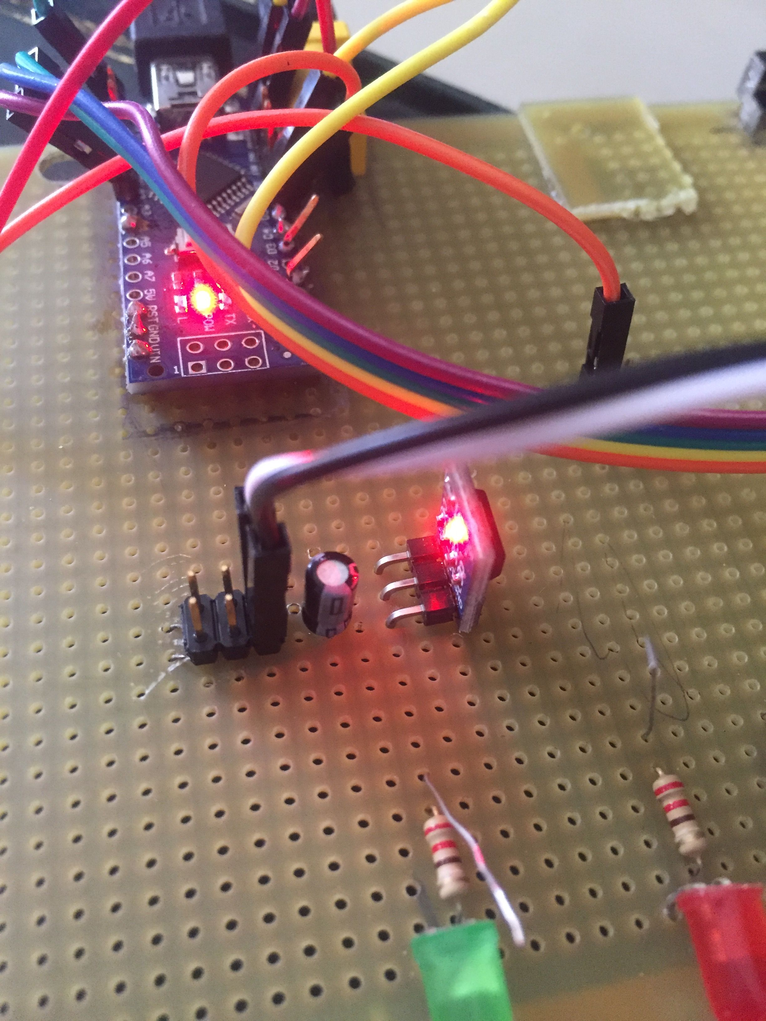
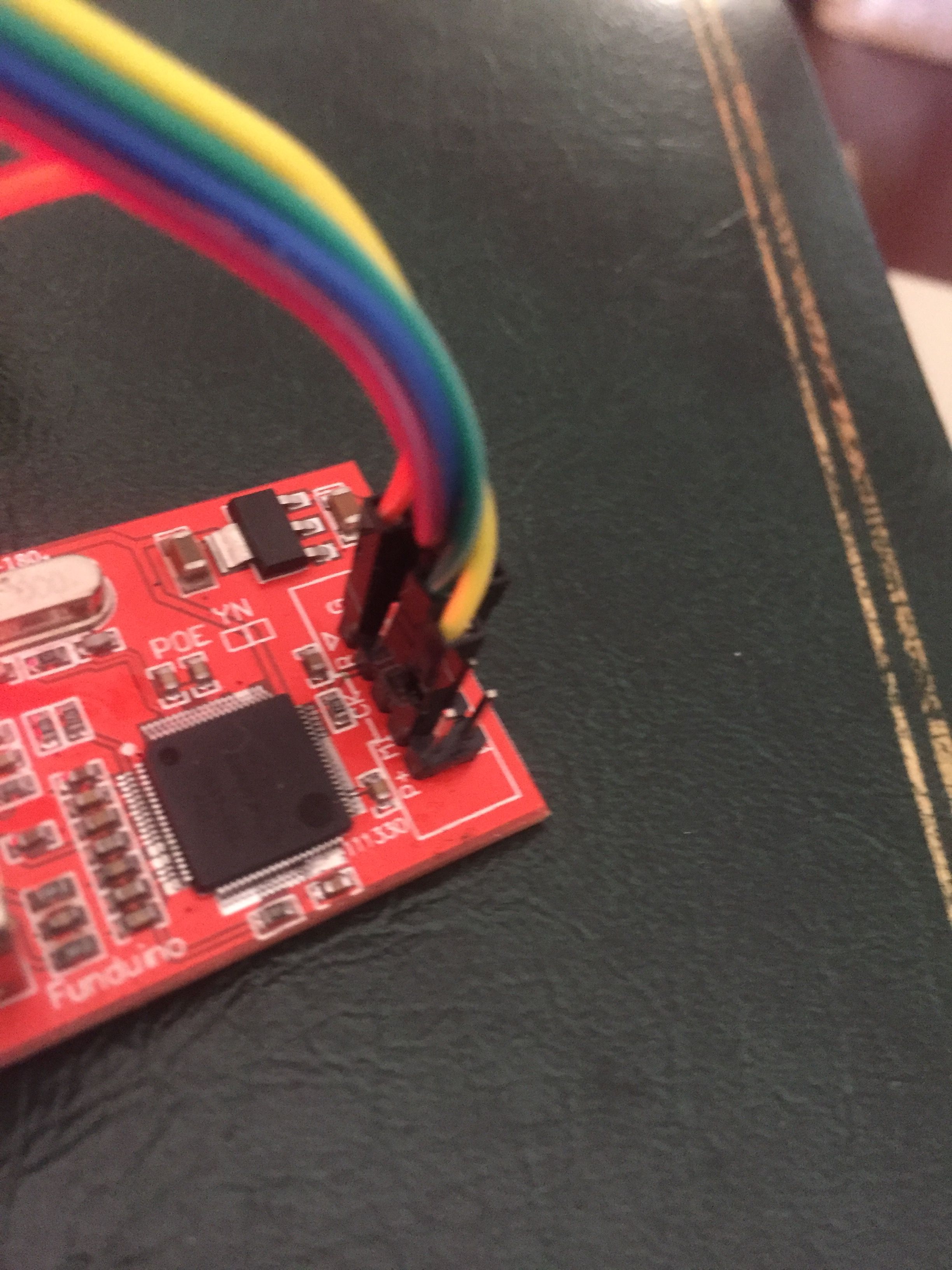
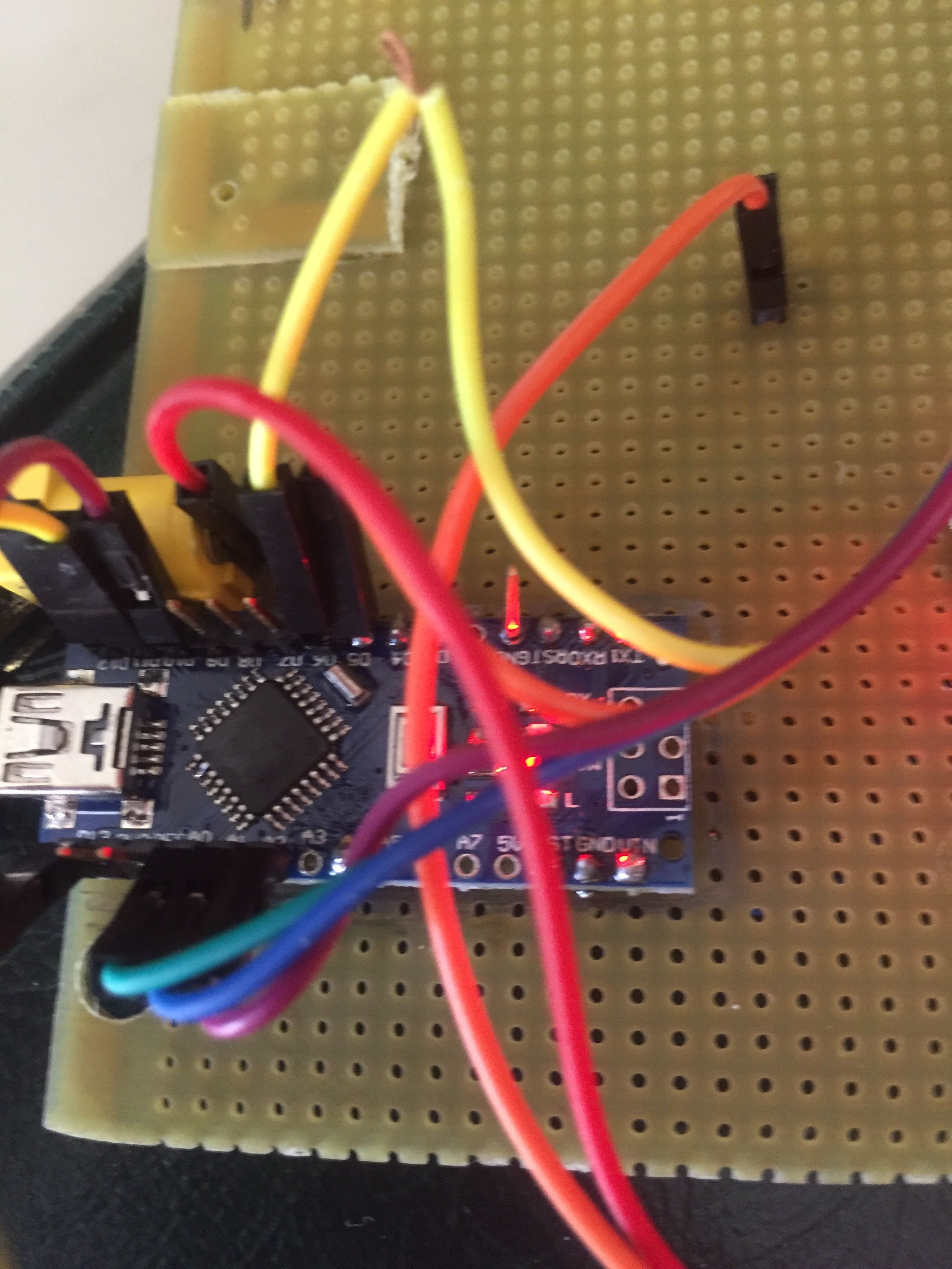
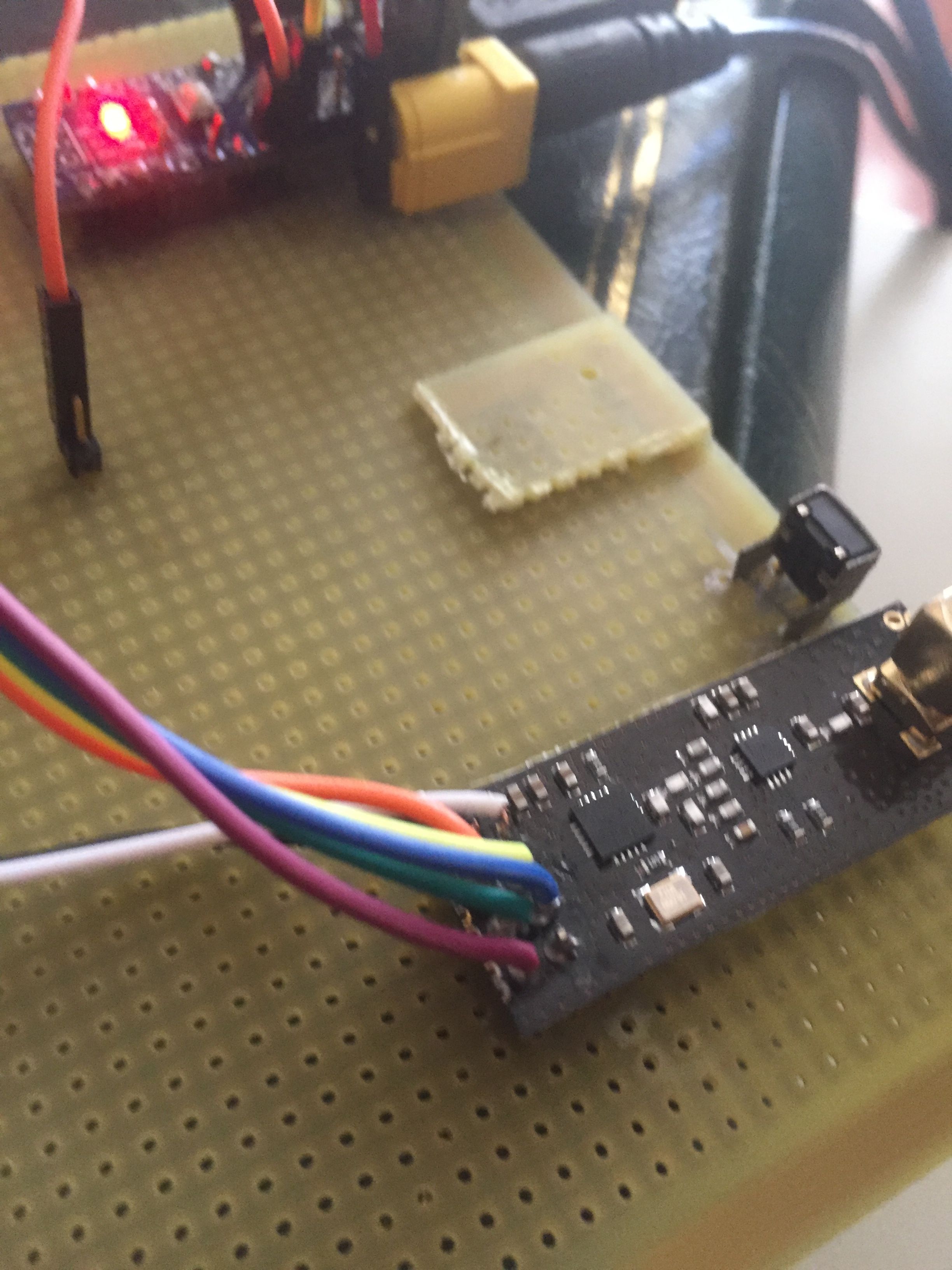
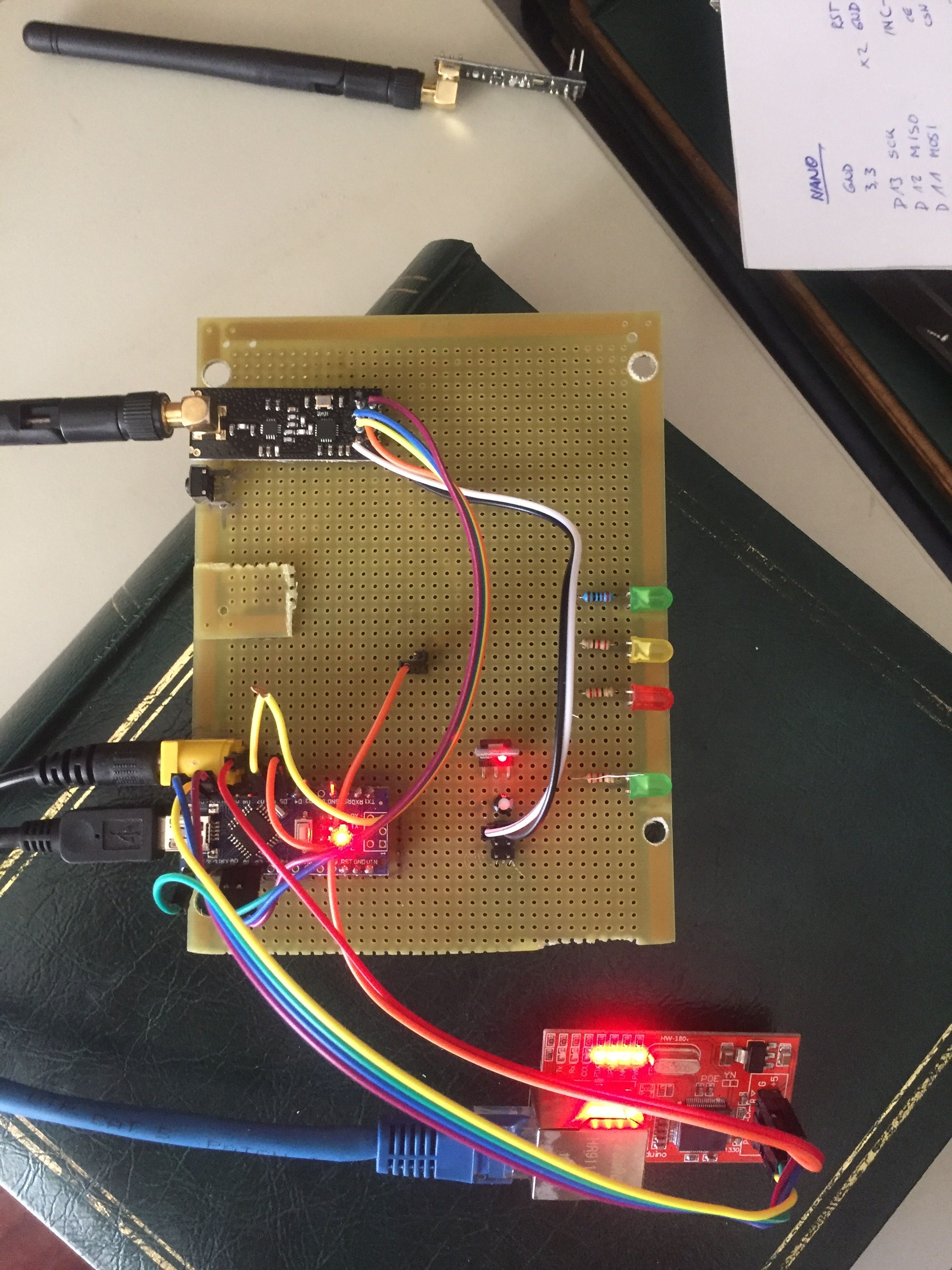
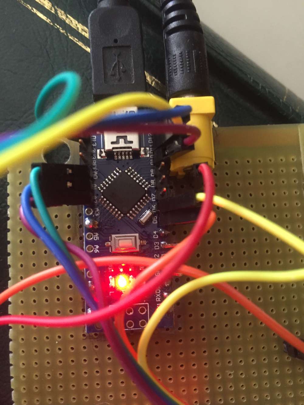
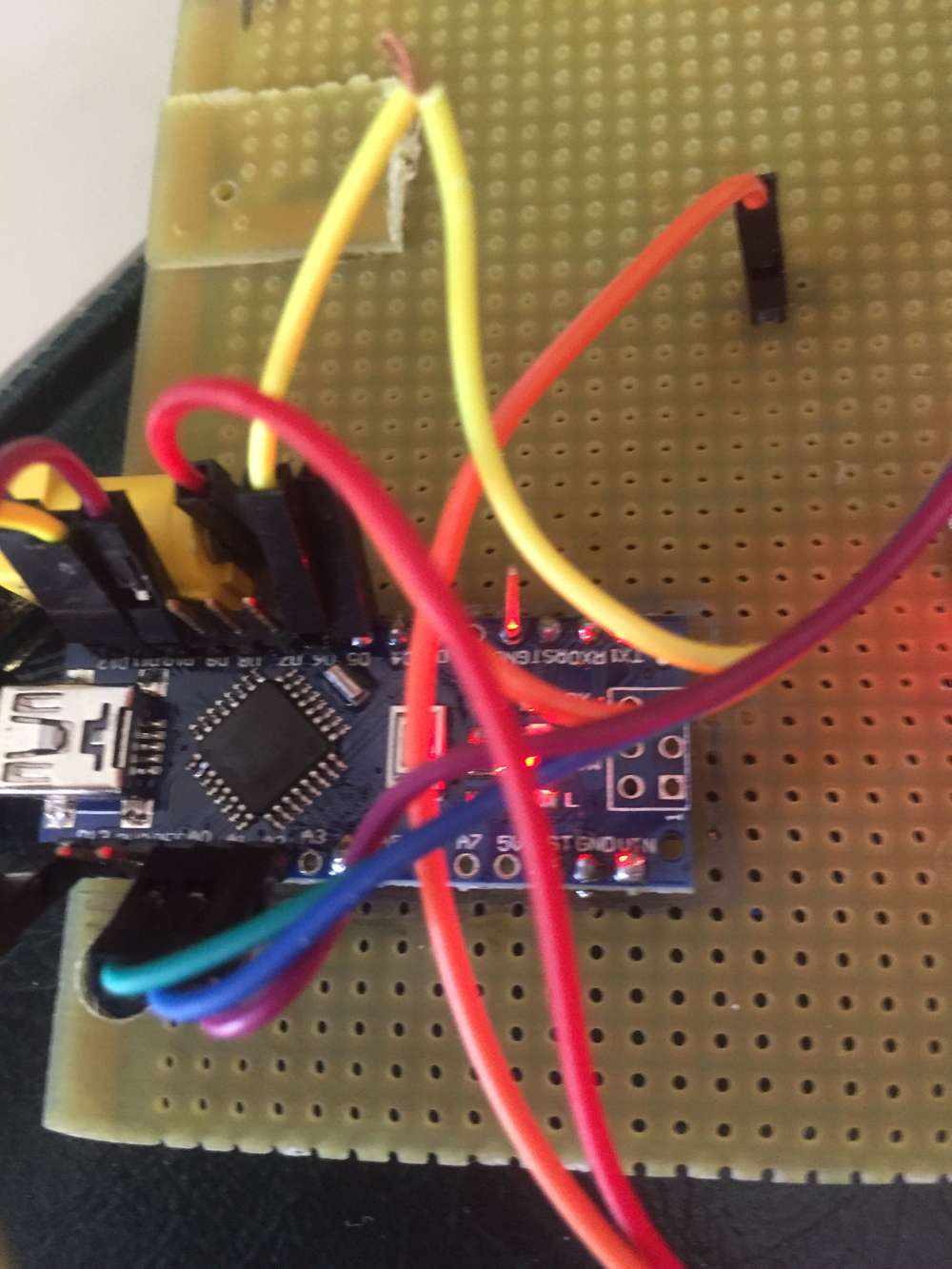
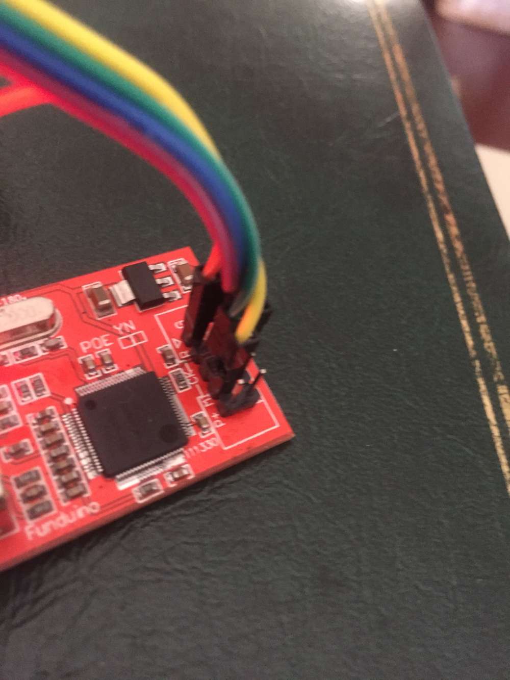
i built the following:
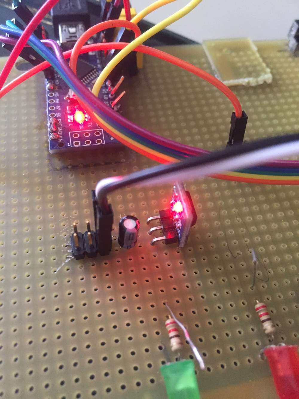
With the following code:
// Enable debug prints to serial monitor
#define MY_DEBUG

// Enable and select radio type attached
#define MY_RADIO_RF24
//#define MY_RADIO_NRF5_ESB
//#define MY_RADIO_RFM69
//#define MY_RADIO_RFM95

// Enable gateway ethernet module type
#define MY_GATEWAY_W5100

// W5100 Ethernet module SPI enable (optional if using a shield/module that manages SPI_EN signal)
//#define MY_W5100_SPI_EN 4

// Enable Soft SPI for NRF radio (note different radio wiring is required)
// The W5100 ethernet module seems to have a hard time co-operate with
// radio on the same spi bus.
#if !defined(MY_W5100_SPI_EN) && !defined(ARDUINO_ARCH_SAMD)
#define MY_SOFTSPI
#define MY_SOFT_SPI_SCK_PIN 14
#define MY_SOFT_SPI_MISO_PIN 16
#define MY_SOFT_SPI_MOSI_PIN 15
#endif

// When W5100 is connected we have to move CE/CSN pins for NRF radio
#ifndef MY_RF24_CE_PIN
#define MY_RF24_CE_PIN 5
#endif
#ifndef MY_RF24_CS_PIN
#define MY_RF24_CS_PIN 6
#endif

// Enable UDP communication
//#define MY_USE_UDP  // If using UDP you need to set MY_CONTROLLER_IP_ADDRESS or MY_CONTROLLER_URL_ADDRESS below

// Enable MY_IP_ADDRESS here if you want a static ip address (no DHCP)
#define MY_IP_ADDRESS 192,168,80,15

// If using static ip you can define Gateway and Subnet address as well
//#define MY_IP_GATEWAY_ADDRESS 192,168,80,1
#define MY_IP_SUBNET_ADDRESS 255,255,255,0

// Renewal period if using DHCP
//#define MY_IP_RENEWAL_INTERVAL 60000

// The port to keep open on node server mode / or port to contact in client mode
#define MY_PORT 5003

// Controller ip address. Enables client mode (default is "server" mode).
// Also enable this if MY_USE_UDP is used and you want sensor data sent somewhere.
//#define MY_CONTROLLER_IP_ADDRESS 192, 168, 178, 254
//#define MY_CONTROLLER_URL_ADDRESS "my.controller.org"

// The MAC address can be anything you want but should be unique on your network.
// Newer boards have a MAC address printed on the underside of the PCB, which you can (optionally) use.
// Note that most of the Arduino examples use  "DEAD BEEF FEED" for the MAC address.
#define MY_MAC_ADDRESS 0x00, 0x40, 0xFD, 0xEF, 0x35, 0x76


// Enable inclusion mode
#define MY_INCLUSION_MODE_FEATURE
// Enable Inclusion mode button on gateway
#define MY_INCLUSION_BUTTON_FEATURE
// Set inclusion mode duration (in seconds)
#define MY_INCLUSION_MODE_DURATION 60
// Digital pin used for inclusion mode button
#define MY_INCLUSION_MODE_BUTTON_PIN  3

// Set blinking period
#define MY_DEFAULT_LED_BLINK_PERIOD 300

// Flash leds on rx/tx/err
// Uncomment to override default HW configurations
#define MY_DEFAULT_ERR_LED_PIN 7  // Error led pin
#define MY_DEFAULT_RX_LED_PIN  8  // Receive led pin
#define MY_DEFAULT_TX_LED_PIN  9  // Transmit led pin

#if defined(MY_USE_UDP)
#include <EthernetUdp.h>
#endif
#include <SPI.h>
#include <Ethernet.h>
#include <MySensors.h>

void setup()
{
  // Setup locally attached sensors
}

void presentation()
{
  // Present locally attached sensors here
}

void loop()
{
  // Send locally attached sensors data here
}
Serial monitor shows:
0 MCO:BGN:INIT GW,CP=RNNGA---,FQ=16,REL=255,VER=2.3.2
4 TSM:INIT
5 TSF:WUR:MS=0
12 TSM:INIT:TSP OK
13 TSM:INIT:GW MODE
15 TSM:READY:ID=0,PAR=0,DIS=0
18 MCO:REG:NOT NEEDED
642 GWT:TIN:IP=255.255.255.255
1644 MCO:BGN:STP
1646 MCO:BGN:INIT OK,TSP=1
1648 TSM:READY:NWD REQ
1653 ?TSF:MSG:SEND,0-0-255-255,s=255,c=3,t=20,pt=0,l=0,sg=0,ft=0,st=OK:
Log parser shows:
Node Id	Child Sensor	Command Type	Echo Req/Resp	Type	Payload	Description
0 MCO:BGN:INIT GW,CP=RNNGA---,FQ=16,REL=255,VER=2.3.2	Core initialization of GW, with capabilities RNNGA---, CPU frequency 16 MHz, library version 2.3.2, release 255
4 TSM:INIT	Transition to Init state
5 TSF:WUR:MS=0	Wait until transport ready, timeout 0
12 TSM:INIT:TSP OK	Transition to Init state:TSP OK
13 TSM:INIT:GW MODE	Transition to Init state:GW MODE
15 TSM:READY:ID=0,PAR=0,DIS=0	Transport ready, node id 0, parent node id 0, distance to GW is 0
18 MCO:REG:NOT NEEDED	No registration needed (i.e. GW)
Unknown	642 GWT:TIN:IP=255.255.255.255
1644 MCO:BGN:STP	Callback setup()
1646 MCO:BGN:INIT OK,TSP=1	Core initialized, transport status 1, (1=initialized, 0=not initialized, NA=not available)
1648 TSM:READY:NWD REQ	Send transport network discovery request
1653 ?TSF:MSG:SEND,0-0-255-255,s=255,c=3,t=20,pt=0,l=0,sg=0,ft=0,st=OK:	Sent Message without radio ACK
Sender: 0
Last Node: 0
Next Node: 255
Destination: 255
Sensor Id: 255
Command: INTERNAL
Message Type:I_DISCOVER_REQUEST
Payload Type: P_STRING
Payload Length: 0
Signing: 0
Failed uplink counter: 0
Status: OK (OK=success, NACK=no radio ACK received)
Payload:
but nothing:
- can't ping to it.
- arp -a shows the address, but no the mac.
ANy hint?
-
Hi,
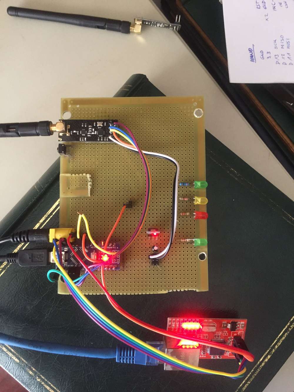
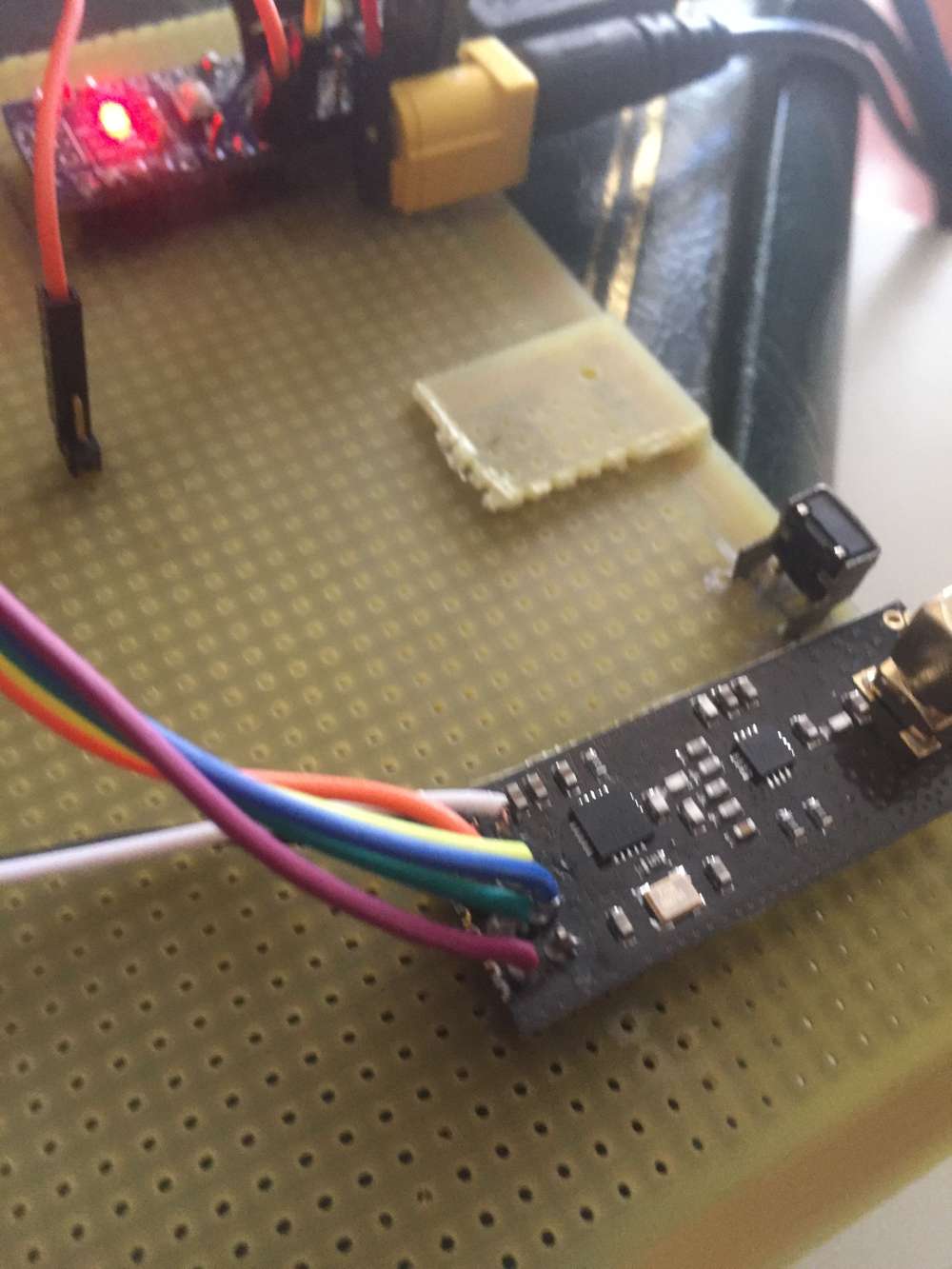
i built the following:
With the following code:
// Enable debug prints to serial monitor
#define MY_DEBUG

// Enable and select radio type attached
#define MY_RADIO_RF24
//#define MY_RADIO_NRF5_ESB
//#define MY_RADIO_RFM69
//#define MY_RADIO_RFM95

// Enable gateway ethernet module type
#define MY_GATEWAY_W5100

// W5100 Ethernet module SPI enable (optional if using a shield/module that manages SPI_EN signal)
//#define MY_W5100_SPI_EN 4

// Enable Soft SPI for NRF radio (note different radio wiring is required)
// The W5100 ethernet module seems to have a hard time co-operate with
// radio on the same spi bus.
#if !defined(MY_W5100_SPI_EN) && !defined(ARDUINO_ARCH_SAMD)
#define MY_SOFTSPI
#define MY_SOFT_SPI_SCK_PIN 14
#define MY_SOFT_SPI_MISO_PIN 16
#define MY_SOFT_SPI_MOSI_PIN 15
#endif

// When W5100 is connected we have to move CE/CSN pins for NRF radio
#ifndef MY_RF24_CE_PIN
#define MY_RF24_CE_PIN 5
#endif
#ifndef MY_RF24_CS_PIN
#define MY_RF24_CS_PIN 6
#endif

// Enable UDP communication
//#define MY_USE_UDP  // If using UDP you need to set MY_CONTROLLER_IP_ADDRESS or MY_CONTROLLER_URL_ADDRESS below

// Enable MY_IP_ADDRESS here if you want a static ip address (no DHCP)
#define MY_IP_ADDRESS 192,168,80,15

// If using static ip you can define Gateway and Subnet address as well
//#define MY_IP_GATEWAY_ADDRESS 192,168,80,1
#define MY_IP_SUBNET_ADDRESS 255,255,255,0

// Renewal period if using DHCP
//#define MY_IP_RENEWAL_INTERVAL 60000

// The port to keep open on node server mode / or port to contact in client mode
#define MY_PORT 5003

// Controller ip address. Enables client mode (default is "server" mode).
// Also enable this if MY_USE_UDP is used and you want sensor data sent somewhere.
//#define MY_CONTROLLER_IP_ADDRESS 192, 168, 178, 254
//#define MY_CONTROLLER_URL_ADDRESS "my.controller.org"

// The MAC address can be anything you want but should be unique on your network.
// Newer boards have a MAC address printed on the underside of the PCB, which you can (optionally) use.
// Note that most of the Arduino examples use  "DEAD BEEF FEED" for the MAC address.
#define MY_MAC_ADDRESS 0x00, 0x40, 0xFD, 0xEF, 0x35, 0x76


// Enable inclusion mode
#define MY_INCLUSION_MODE_FEATURE
// Enable Inclusion mode button on gateway
#define MY_INCLUSION_BUTTON_FEATURE
// Set inclusion mode duration (in seconds)
#define MY_INCLUSION_MODE_DURATION 60
// Digital pin used for inclusion mode button
#define MY_INCLUSION_MODE_BUTTON_PIN  3

// Set blinking period
#define MY_DEFAULT_LED_BLINK_PERIOD 300

// Flash leds on rx/tx/err
// Uncomment to override default HW configurations
#define MY_DEFAULT_ERR_LED_PIN 7  // Error led pin
#define MY_DEFAULT_RX_LED_PIN  8  // Receive led pin
#define MY_DEFAULT_TX_LED_PIN  9  // Transmit led pin

#if defined(MY_USE_UDP)
#include <EthernetUdp.h>
#endif
#include <SPI.h>
#include <Ethernet.h>
#include <MySensors.h>

void setup()
{
  // Setup locally attached sensors
}

void presentation()
{
  // Present locally attached sensors here
}

void loop()
{
  // Send locally attached sensors data here
}
Serial monitor shows:
0 MCO:BGN:INIT GW,CP=RNNGA---,FQ=16,REL=255,VER=2.3.2
4 TSM:INIT
5 TSF:WUR:MS=0
12 TSM:INIT:TSP OK
13 TSM:INIT:GW MODE
15 TSM:READY:ID=0,PAR=0,DIS=0
18 MCO:REG:NOT NEEDED
642 GWT:TIN:IP=255.255.255.255
1644 MCO:BGN:STP
1646 MCO:BGN:INIT OK,TSP=1
1648 TSM:READY:NWD REQ
1653 ?TSF:MSG:SEND,0-0-255-255,s=255,c=3,t=20,pt=0,l=0,sg=0,ft=0,st=OK:
Log parser shows:
Node Id	Child Sensor	Command Type	Echo Req/Resp	Type	Payload	Description
0 MCO:BGN:INIT GW,CP=RNNGA---,FQ=16,REL=255,VER=2.3.2	Core initialization of GW, with capabilities RNNGA---, CPU frequency 16 MHz, library version 2.3.2, release 255
4 TSM:INIT	Transition to Init state
5 TSF:WUR:MS=0	Wait until transport ready, timeout 0
12 TSM:INIT:TSP OK	Transition to Init state:TSP OK
13 TSM:INIT:GW MODE	Transition to Init state:GW MODE
15 TSM:READY:ID=0,PAR=0,DIS=0	Transport ready, node id 0, parent node id 0, distance to GW is 0
18 MCO:REG:NOT NEEDED	No registration needed (i.e. GW)
Unknown	642 GWT:TIN:IP=255.255.255.255
1644 MCO:BGN:STP	Callback setup()
1646 MCO:BGN:INIT OK,TSP=1	Core initialized, transport status 1, (1=initialized, 0=not initialized, NA=not available)
1648 TSM:READY:NWD REQ	Send transport network discovery request
1653 ?TSF:MSG:SEND,0-0-255-255,s=255,c=3,t=20,pt=0,l=0,sg=0,ft=0,st=OK:	Sent Message without radio ACK
Sender: 0
Last Node: 0
Next Node: 255
Destination: 255
Sensor Id: 255
Command: INTERNAL
Message Type:I_DISCOVER_REQUEST
Payload Type: P_STRING
Payload Length: 0
Signing: 0
Failed uplink counter: 0
Status: OK (OK=success, NACK=no radio ACK received)
Payload:
but nothing:
- can't ping to it.
- arp -a shows the address, but no the mac.
ANy hint?
For some reason the Gateway uses IP=255.255.255.255 (which is not a valid IP address) instead of the one you specified.
There is plenty of free ram after compiling the sketch, so ram shouldn't be a problem.
There have been a few similar reports earlier. https://forum.mysensors.org/post/82366 seems to be the only one that has a suggested solution.
Which version of the Arduino IDE and which AVR board version are you using?


Hello! It looks like you're interested in this conversation, but you don't have an account yet.
Getting fed up of having to scroll through the same posts each visit? When you register for an account, you'll always come back to exactly where you were before, and choose to be notified of new replies (either via email, or push notification). You'll also be able to save bookmarks and upvote posts to show your appreciation to other community members.
With your input, this post could be even better 💗
Register Login