Wemos d1 mini : gateway error .
-
Oh, I will check the wiring ...
I taught It means that it can't connect to wifi ...So it's normal that I can't ping the wemos ...
For the sketch I just upload the example sketch for esp8266gateway..
/* * The MySensors Arduino library handles the wireless radio link and protocol * between your home built sensors/actuators and HA controller of choice. * The sensors forms a self healing radio network with optional repeaters. Each * repeater and gateway builds a routing tables in EEPROM which keeps track of the * network topology allowing messages to be routed to nodes. * * Created by Henrik Ekblad <henrik.ekblad@mysensors.org> * Copyright (C) 2013-2019 Sensnology AB * Full contributor list: https://github.com/mysensors/MySensors/graphs/contributors * * Documentation: http://www.mysensors.org * Support Forum: http://forum.mysensors.org * * This program is free software; you can redistribute it and/or * modify it under the terms of the GNU General Public License * version 2 as published by the Free Software Foundation. * ******************************* * * REVISION HISTORY * Version 1.0 - Henrik Ekblad * Contribution by a-lurker and Anticimex, * Contribution by Norbert Truchsess <norbert.truchsess@t-online.de> * Contribution by Ivo Pullens (ESP8266 support) * * DESCRIPTION * The EthernetGateway sends data received from sensors to the WiFi link. * The gateway also accepts input on ethernet interface, which is then sent out to the radio network. * * VERA CONFIGURATION: * Enter "ip-number:port" in the ip-field of the Arduino GW device. This will temporarily override any serial configuration for the Vera plugin. * E.g. If you want to use the default values in this sketch enter: 192.168.178.66:5003 * * LED purposes: * - To use the feature, uncomment any of the MY_DEFAULT_xx_LED_PINs in your sketch, only the LEDs that is defined is used. * - RX (green) - blink fast on radio message received. In inclusion mode will blink fast only on presentation received * - TX (yellow) - blink fast on radio message transmitted. In inclusion mode will blink slowly * - ERR (red) - fast blink on error during transmission error or receive crc error * * See https://www.mysensors.org/build/connect_radio for wiring instructions. * * If you are using a "barebone" ESP8266, see * https://www.mysensors.org/build/esp8266_gateway#wiring-for-barebone-esp8266 * * Inclusion mode button: * - Connect GPIO5 (=D1) via switch to GND ('inclusion switch') * * Hardware SHA204 signing is currently not supported! * * Make sure to fill in your ssid and WiFi password below for ssid & pass. */ // Enable debug prints to serial monitor #define MY_DEBUG // Use a bit lower baudrate for serial prints on ESP8266 than default in MyConfig.h #define MY_BAUD_RATE 9600 // Enables and select radio type (if attached) #define MY_RADIO_RF24 //#define MY_RADIO_RFM69 //#define MY_RADIO_RFM95 #define MY_GATEWAY_ESP8266 #define MY_WIFI_SSID "xxxx" #define MY_WIFI_PASSWORD "xxxxxx" // Enable UDP communication //#define MY_USE_UDP // If using UDP you need to set MY_CONTROLLER_IP_ADDRESS or MY_CONTROLLER_URL_ADDRESS below // Set the hostname for the WiFi Client. This is the hostname // it will pass to the DHCP server if not static. #define MY_HOSTNAME "ESP8266_GW" // Enable MY_IP_ADDRESS here if you want a static ip address (no DHCP) #define MY_IP_ADDRESS 192,168,1,112 // If using static ip you can define Gateway and Subnet address as well #define MY_IP_GATEWAY_ADDRESS 192,168,1,1 #define MY_IP_SUBNET_ADDRESS 255,255,255,0 // The port to keep open on node server mode #define MY_PORT 5003 // How many clients should be able to connect to this gateway (default 1) #define MY_GATEWAY_MAX_CLIENTS 2 // Controller ip address. Enables client mode (default is "server" mode). // Also enable this if MY_USE_UDP is used and you want sensor data sent somewhere. //#define MY_CONTROLLER_IP_ADDRESS 192, 168, 178, 68 //#define MY_CONTROLLER_URL_ADDRESS "my.controller.org" // Enable inclusion mode //#define MY_INCLUSION_MODE_FEATURE // Enable Inclusion mode button on gateway //#define MY_INCLUSION_BUTTON_FEATURE // Set inclusion mode duration (in seconds) //#define MY_INCLUSION_MODE_DURATION 60 // Digital pin used for inclusion mode button //#define MY_INCLUSION_MODE_BUTTON_PIN D1 // Set blinking period //#define MY_DEFAULT_LED_BLINK_PERIOD 300 // Flash leds on rx/tx/err // Led pins used if blinking feature is enabled above //#define MY_DEFAULT_ERR_LED_PIN 16 // Error led pin //#define MY_DEFAULT_RX_LED_PIN 16 // Receive led pin //#define MY_DEFAULT_TX_LED_PIN 16 // the PCB, on board LED #include <MySensors.h> void setup() { // Setup locally attached sensors } void presentation() { // Present locally attached sensors here } void loop() { // Send locally attached sensors data here } -
Now the wiring check.
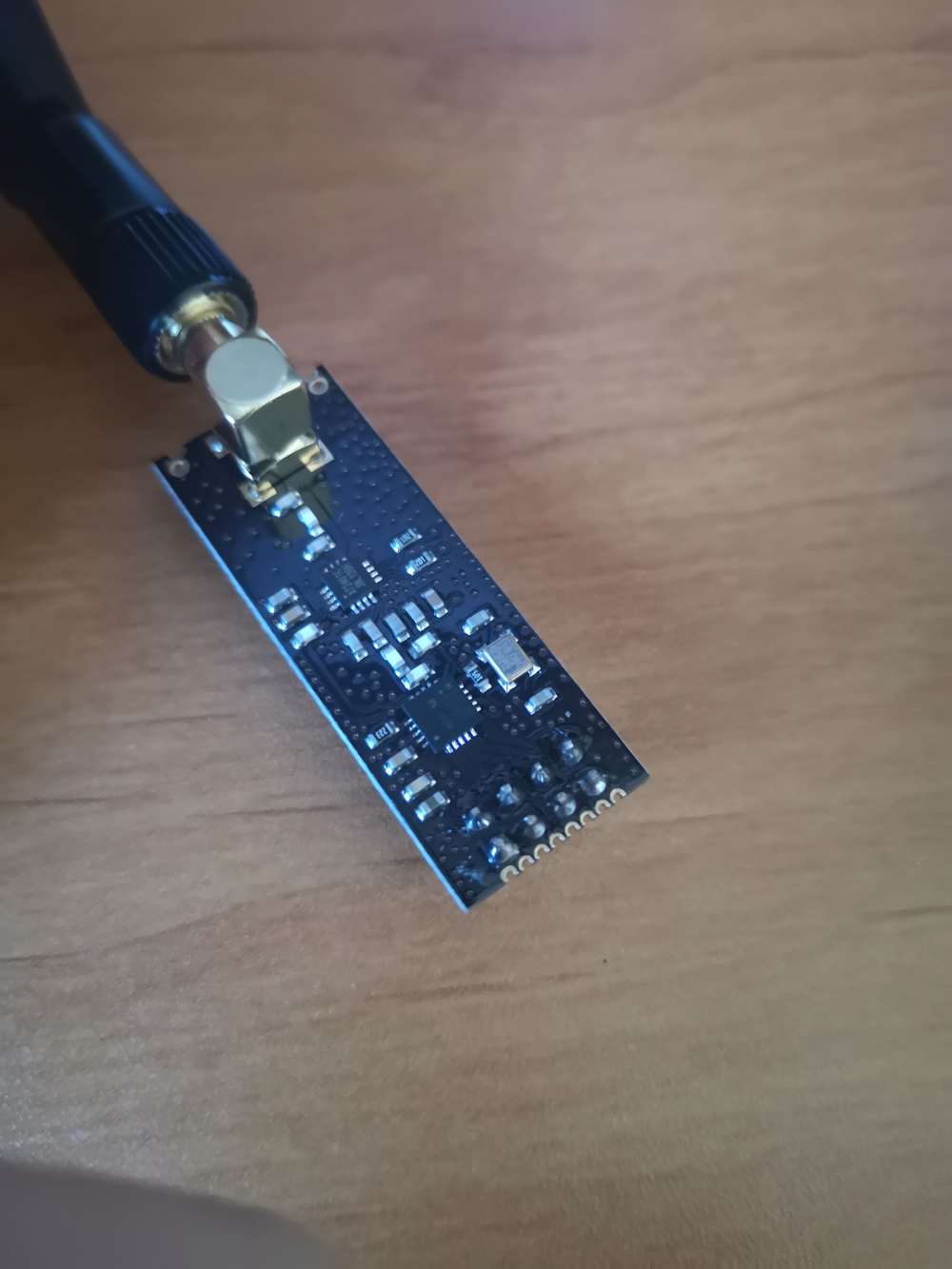
I have a nrf24l01 with antenna, and nothing is written on the board ...
Does someone have a wiring diagram for that nrf module ?Thank you.
-
Now the wiring check.
I have a nrf24l01 with antenna, and nothing is written on the board ...
Does someone have a wiring diagram for that nrf module ?Thank you.
@David-Marlinge could you expand on what you mean by "nothing is written on the board". Which board?
The wiring is available at https://www.mysensors.org/build/connect_radio#nrf24l01+-&-esp8266
-
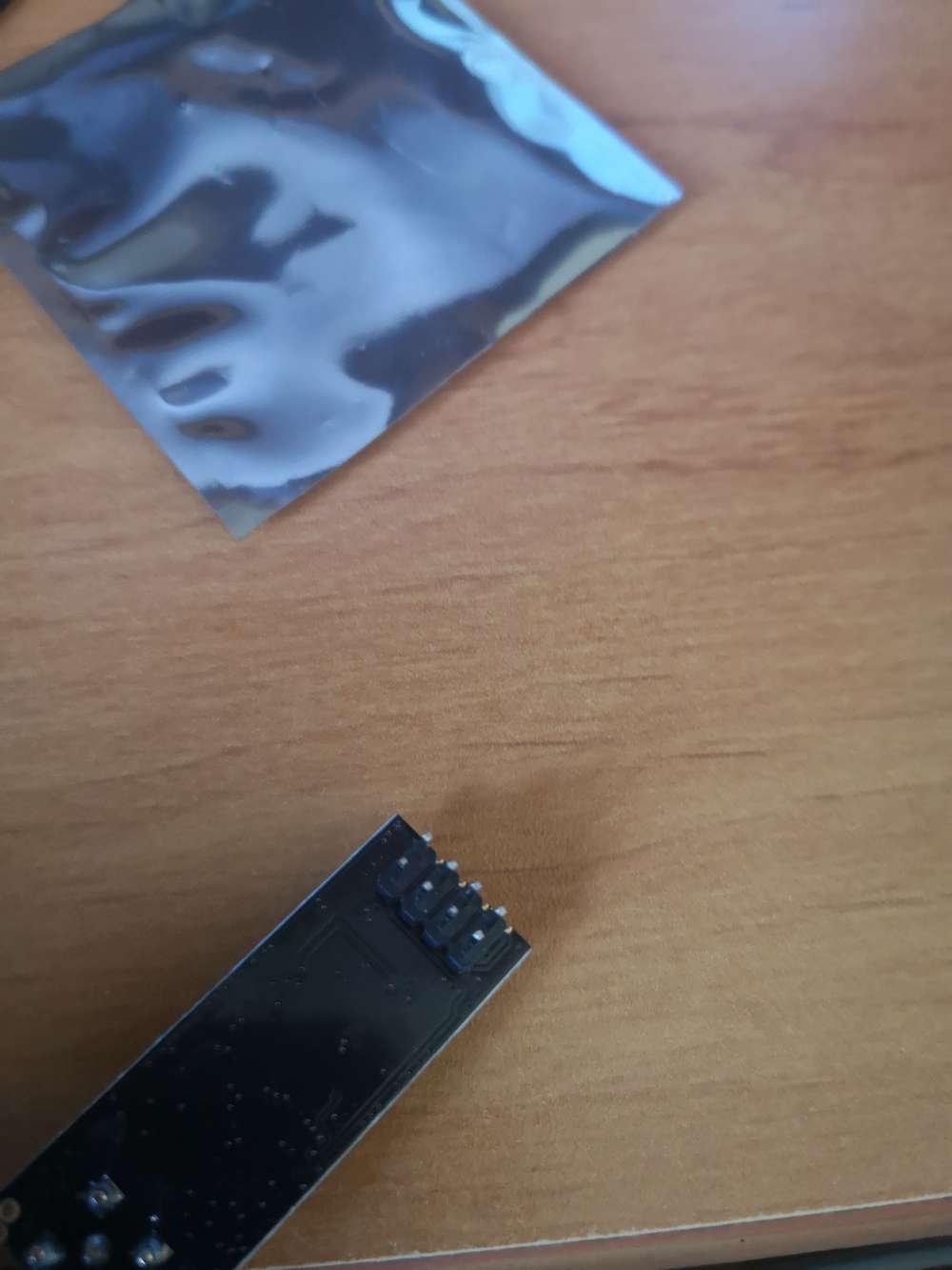
nothing is written on the nrf24L01 board ...
I send a picture ...
-
nothing is written on the nrf24L01 board ...
I send a picture ...
-
If it's the same wiring, I connect like your link, but it does not work.
Now I can ping the wifi adress even if the nrf24l01 is not plugin ... In fact It doesn't take the adress I give in the sketch ....
-
What I want to say, is that nothing is written on the pin ... So How can I be sure where the gnd, vcc and so on are ???
-
What I want to say, is that nothing is written on the pin ... So How can I be sure where the gnd, vcc and so on are ???
-
I have already check, nothing is written on the store where i bought them ...
Is tha capacitor needed ? and Must the whole thing works connected on a PC usb ?
-
So I check the wiring. I think a wire was not well plugged.
Now it works.
I have such "sentences" :
11:52:22.169 -> 12496 GWT:TIN:CONNECTING...
11:52:22.499 -> scandone
11:52:23.204 -> 13525 GWT:TIN:CONNECTING...
11:52:23.204 -> 13555 GWT:TIN:IP: 192.168.1.111
11:52:23.251 -> 13588 MCO:BGN:STP
11:52:23.251 -> 13607 MCO:BGN:INIT OK,TSP=1
11:52:23.298 -> 13637 TSM:READY:NWD REQ
11:52:23.346 -> 13665 ?TSF:MSG:SEND,0-0-255-255,s=255,c=3,t=20,pt=0,l=0,sg=0,ft=0,st=OK:
11:52:23.535 -> pm open,type:2 0
Hello! It looks like you're interested in this conversation, but you don't have an account yet.
Getting fed up of having to scroll through the same posts each visit? When you register for an account, you'll always come back to exactly where you were before, and choose to be notified of new replies (either via email, or push notification). You'll also be able to save bookmarks and upvote posts to show your appreciation to other community members.
With your input, this post could be even better 💗
Register Login