Arduino+M5100 cannot connect to LAN
-
Dears,
I use Arduino Mega and M5100 ethernet Shield. I put prepared sketch but it won't connect to my local LAN. Could you please check my sketch?code_text/* * The MySensors Arduino library handles the wireless radio link and protocol * between your home built sensors/actuators and HA controller of choice. * The sensors forms a self healing radio network with optional repeaters. Each * repeater and gateway builds a routing tables in EEPROM which keeps track of the * network topology allowing messages to be routed to nodes. * * Created by Henrik Ekblad <henrik.ekblad@mysensors.org> * Copyright (C) 2013-2019 Sensnology AB * Full contributor list: https://github.com/mysensors/MySensors/graphs/contributors * * Documentation: http://www.mysensors.org * Support Forum: http://forum.mysensors.org * * This program is free software; you can redistribute it and/or * modify it under the terms of the GNU General Public License * version 2 as published by the Free Software Foundation. * ******************************* * * REVISION HISTORY * Version 1.0 - Henrik Ekblad * Contribution by a-lurker and Anticimex * Contribution by Norbert Truchsess <norbert.truchsess@t-online.de> * Contribution by Tomas Hozza <thozza@gmail.com> * * * DESCRIPTION * The EthernetGateway sends data received from sensors to the ethernet link. * The gateway also accepts input on ethernet interface, which is then sent out to the radio network. * * The GW code is designed for Arduino 328p / 16MHz. ATmega168 does not have enough memory to run this program. * * LED purposes: * - To use the feature, uncomment MY_DEFAULT_xxx_LED_PIN in the sketch below * - RX (green) - blink fast on radio message received. In inclusion mode will blink fast only on presentation received * - TX (yellow) - blink fast on radio message transmitted. In inclusion mode will blink slowly * - ERR (red) - fast blink on error during transmission error or receive crc error * * See http://www.mysensors.org/build/ethernet_gateway for wiring instructions. * */ // Enable debug prints to serial monitor #define MY_DEBUG // Enable and select radio type attached #define MY_RADIO_RF24 //#define MY_RADIO_NRF5_ESB //#define MY_RADIO_RFM69 //#define MY_RADIO_RFM95 // Enable gateway ethernet module type #define MY_GATEWAY_W5100 // W5100 Ethernet module SPI enable (optional if using a shield/module that manages SPI_EN signal) //#define MY_W5100_SPI_EN 4 // Enable Soft SPI for NRF radio (note different radio wiring is required) // The W5100 ethernet module seems to have a hard time co-operate with // radio on the same spi bus. #if !defined(MY_W5100_SPI_EN) && !defined(ARDUINO_ARCH_SAMD) #define MY_SOFTSPI #define MY_SOFT_SPI_SCK_PIN 14 #define MY_SOFT_SPI_MISO_PIN 16 #define MY_SOFT_SPI_MOSI_PIN 15 #endif // When W5100 is connected we have to move CE/CSN pins for NRF radio #ifndef MY_RF24_CE_PIN #define MY_RF24_CE_PIN 5 #endif #ifndef MY_RF24_CS_PIN #define MY_RF24_CS_PIN 6 #endif // Enable UDP communication //#define MY_USE_UDP // If using UDP you need to set MY_CONTROLLER_IP_ADDRESS or MY_CONTROLLER_URL_ADDRESS below // Enable MY_IP_ADDRESS here if you want a static ip address (no DHCP) #define MY_IP_ADDRESS 192,168,0,201 // If using static ip you can define Gateway and Subnet address as well #define MY_IP_GATEWAY_ADDRESS 192,168,0,1 #define MY_IP_SUBNET_ADDRESS 255,255,255,0 // Renewal period if using DHCP //#define MY_IP_RENEWAL_INTERVAL 60000 // The port to keep open on node server mode / or port to contact in client mode #define MY_PORT 5003 // Controller ip address. Enables client mode (default is "server" mode). // Also enable this if MY_USE_UDP is used and you want sensor data sent somewhere. //#define MY_CONTROLLER_IP_ADDRESS 192, 168, 178, 254 //#define MY_CONTROLLER_URL_ADDRESS "my.controller.org" // The MAC address can be anything you want but should be unique on your network. // Newer boards have a MAC address printed on the underside of the PCB, which you can (optionally) use. // Note that most of the Arduino examples use "DEAD BEEF FEED" for the MAC address. #define MY_MAC_ADDRESS 0xDE, 0xAD, 0xBE, 0xEF, 0xFE, 0xED // Enable inclusion mode #define MY_INCLUSION_MODE_FEATURE // Enable Inclusion mode button on gateway //#define MY_INCLUSION_BUTTON_FEATURE // Set inclusion mode duration (in seconds) #define MY_INCLUSION_MODE_DURATION 60 // Digital pin used for inclusion mode button //#define MY_INCLUSION_MODE_BUTTON_PIN 3 // Set blinking period #define MY_DEFAULT_LED_BLINK_PERIOD 300 // Flash leds on rx/tx/err // Uncomment to override default HW configurations //#define MY_DEFAULT_ERR_LED_PIN 7 // Error led pin //#define MY_DEFAULT_RX_LED_PIN 8 // Receive led pin //#define MY_DEFAULT_TX_LED_PIN 9 // Transmit led pin #if defined(MY_USE_UDP) #include <EthernetUdp.h> #endif #include <Ethernet.h> #include <MySensors.h> #include <Bounce2.h> // Enable repeater functionality for this node #define MY_REPEATER_FEATURE #define RELAY_LA_01 4 // Arduino Digital I/O pin number for first relay (second on pin+1 etc) #define RELAY_LA_02 5 #define RELAY_LA_03 6 #define RELAY_LA_04 7 #define RELAY_LA_05 8 #define RELAY_LA_06 9 #define RELAY_LA_07 10 #define RELAY_LA_08 11 #define RELAY_LA_09 12 #define RELAY_LA_10 13 #define NUMBER_OF_RELAYS 10 // Total number of attached relays #define RELAY_ON 0 // GPIO value to write to turn on attached relay #define RELAY_OFF 1 // GPIO value to write to turn off attached relay #define LA_01 A1 #define LA_02 A2 #define LA_03 A3 #define LA_04 A4 #define LA_05 A5 #define LA_06 A6 #define LA_07 A7 #define LA_08 A8 #define LA_09 A9 #define LA_10 A10 void before() { for (int sensor=1, pin=RELAY_LA_01; sensor<=NUMBER_OF_RELAYS;sensor++, pin++) { // Then set relay pins in output mode pinMode(pin, OUTPUT); // Set relay to last known state (using eeprom storage) digitalWrite(pin, loadState(sensor)?RELAY_ON:RELAY_OFF); } } Bounce debouncer = Bounce(); Bounce debouncer2 = Bounce(); Bounce debouncer3 = Bounce(); Bounce debouncer4 = Bounce(); Bounce debouncer5 = Bounce(); Bounce debouncer6 = Bounce(); Bounce debouncer7 = Bounce(); Bounce debouncer8 = Bounce(); Bounce debouncer9 = Bounce(); Bounce debouncer10 = Bounce(); void setup() { // Setup locally attached sensors delay(10000); // Setup the button. pinMode(LA_01, INPUT_PULLUP); pinMode(LA_02, INPUT_PULLUP); pinMode(LA_03, INPUT_PULLUP); pinMode(LA_04, INPUT_PULLUP); pinMode(LA_05, INPUT_PULLUP); pinMode(LA_06, INPUT_PULLUP); pinMode(LA_07, INPUT_PULLUP); pinMode(LA_08, INPUT_PULLUP); pinMode(LA_09, INPUT_PULLUP); pinMode(LA_10, INPUT_PULLUP); // After setting up the button, setup debouncer. debouncer.attach(LA_01); debouncer.interval(5); debouncer2.attach(LA_02); debouncer2.interval(5); debouncer3.attach(LA_03); debouncer3.interval(5); debouncer4.attach(LA_04); debouncer4.interval(5); debouncer5.attach(LA_05); debouncer5.interval(5); debouncer6.attach(LA_06); debouncer6.interval(5); debouncer7.attach(LA_07); debouncer7.interval(5); debouncer8.attach(LA_08); debouncer8.interval(5); debouncer9.attach(LA_09); debouncer9.interval(5); debouncer10.attach(LA_10); debouncer10.interval(5); //presentation(); } void presentation() { // Send the sketch version information to the gateway and Controller sendSketchInfo("Relay", "1.0"); for (int sensor=1, pin=RELAY_LA_01; sensor<=NUMBER_OF_RELAYS;sensor++, pin++) { // Register all sensors to gw (they will be created as child devices) present(sensor, S_LIGHT); } } MyMessage msg(1, V_LIGHT); MyMessage msg2(2, V_LIGHT); MyMessage msg3(3, V_LIGHT); MyMessage msg4(4, V_LIGHT); MyMessage msg5(5, V_LIGHT); MyMessage msg6(6, V_LIGHT); MyMessage msg7(7, V_LIGHT); MyMessage msg8(8, V_LIGHT); MyMessage msg9(9, V_LIGHT); MyMessage msg10(10, V_LIGHT); void loop() { // Send locally attached sensor data here if (debouncer.update()) { // Get the update value. int value = debouncer.read(); // Send in the new value. if(value == LOW){ saveState(1, !loadState(1)); digitalWrite(RELAY_LA_01, loadState(1)?RELAY_ON:RELAY_OFF); send(msg.set(loadState(1))); } } if (debouncer2.update()) { int value2 = debouncer2.read(); if(value2 == LOW){ saveState(2, !loadState(2)); digitalWrite(RELAY_LA_02, loadState(2)?RELAY_ON:RELAY_OFF); send(msg2.set(loadState(2))); } } if (debouncer3.update()) { // Get the update value. int value3 = debouncer3.read(); // Send in the new value. if(value3 == LOW){ saveState(3, !loadState(3)); digitalWrite(RELAY_LA_03, loadState(3)?RELAY_ON:RELAY_OFF); send(msg3.set(loadState(3))); } } if (debouncer4.update()) { // Get the update value. int value4 = debouncer4.read(); // Send in the new value. if(value4 == LOW){ saveState(4, !loadState(4)); digitalWrite(RELAY_LA_04, loadState(4)?RELAY_ON:RELAY_OFF); send(msg4.set(loadState(4))); } } if (debouncer5.update()) { // Get the update value. int value5 = debouncer5.read(); // Send in the new value. if(value5 == LOW){ saveState(5, !loadState(5)); digitalWrite(RELAY_LA_05, loadState(5)?RELAY_ON:RELAY_OFF); send(msg5.set(loadState(5))); } } if (debouncer6.update()) { // Get the update value. int value6 = debouncer6.read(); // Send in the new value. if(value6 == LOW){ saveState(6, !loadState(6)); digitalWrite(RELAY_LA_06, loadState(6)?RELAY_ON:RELAY_OFF); send(msg6.set(loadState(6))); } } if (debouncer7.update()) { // Get the update value. int value7 = debouncer7.read(); // Send in the new value. if(value7 == LOW){ saveState(7, !loadState(7)); digitalWrite(RELAY_LA_07, loadState(7)?RELAY_ON:RELAY_OFF); send(msg7.set(loadState(7))); } } if (debouncer8.update()) { // Get the update value. int value8 = debouncer8.read(); // Send in the new value. if(value8 == LOW){ saveState(8, !loadState(8)); digitalWrite(RELAY_LA_08, loadState(8)?RELAY_ON:RELAY_OFF); send(msg8.set(loadState(8))); } } if (debouncer9.update()) { // Get the update value. int value9 = debouncer9.read(); // Send in the new value. if(value9 == LOW){ saveState(9, !loadState(9)); digitalWrite(RELAY_LA_09, loadState(9)?RELAY_ON:RELAY_OFF); send(msg9.set(loadState(9))); } } if (debouncer10.update()) { // Get the update value. int value10 = debouncer10.read(); // Send in the new value. if(value10 == LOW){ saveState(10, !loadState(10)); digitalWrite(RELAY_LA_10, loadState(10)?RELAY_ON:RELAY_OFF); send(msg10.set(loadState(10))); } } } void receive(const MyMessage &message) { // We only expect one type of message from controller. But we better check anyway. if (message.type==V_LIGHT) { // Change relay state digitalWrite(message.sensor-1+RELAY_LA_01, message.getBool()?RELAY_ON:RELAY_OFF); // Store state in eeprom saveState(message.sensor, message.getBool()); // Write some debug info Serial.print("Incoming change for sensor:"); Serial.print(message.sensor); Serial.print(", New status: "); Serial.println(message.getBool()); } } -
Welcome to the forum @PZDPRO !
What does the debug output from the gateway say?
If you haven't already, see https://forum.mysensors.org/topic/666/read-this-first-it-could-save-you-a-lot-of-time/ for the most common problems and how to troubleshoot them efficiently.
-
@mfalkvidd
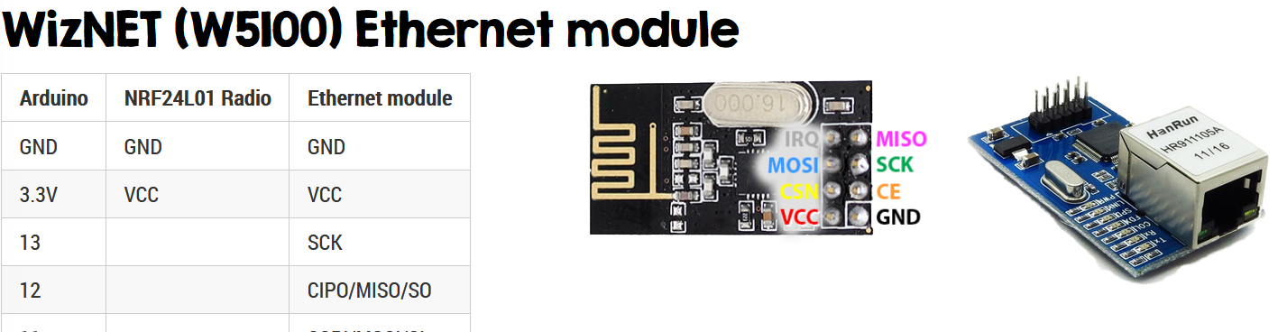
Yes. I use this:
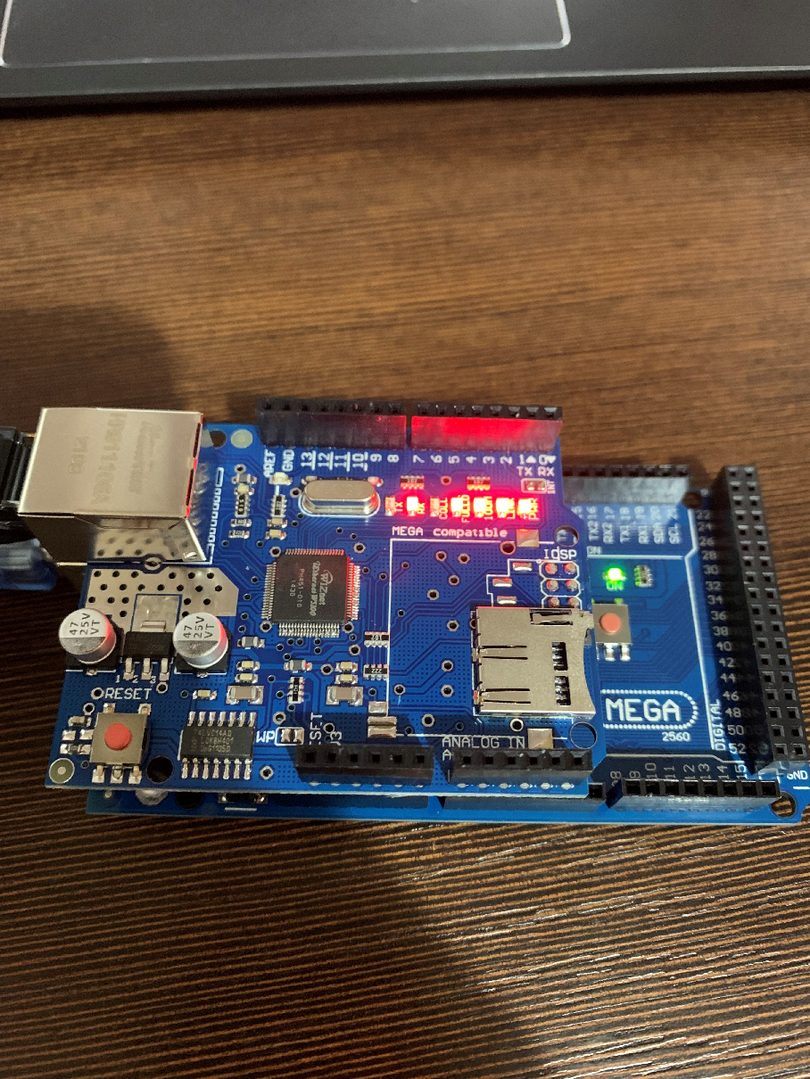
It shouldn't be wired wrong. -
@PZDPRO said in Arduino+M5100 cannot connect to LAN:
#define MY_RADIO_RF24
Comment out this if you don't want to use a nrf24.
@mfalkvidd Hi,
I tried this but still cannot connect to my LAN network. Router doesn't give me IP. I cannot see arduino in HA.
I tried many configurations. Even i put a new sketches from my sensors examples in arduino IDE (GatewayW5100 and GatewayW5100Client).Maybe you someone have working sketch for tests?
Thank you in advance.
-
@PZDPRO all the examples in MySensors are known to work. We wouldn’t have them if they were broken.
What does the debug output say when you have removed the nrf24?
-
@mfalkvidd
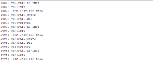
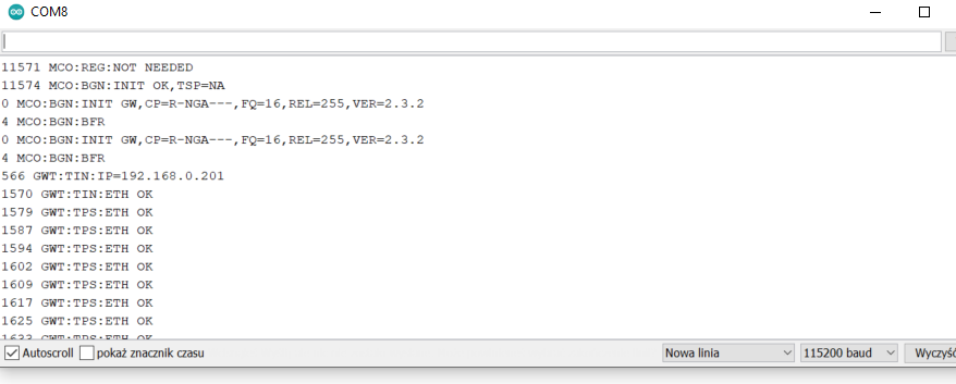
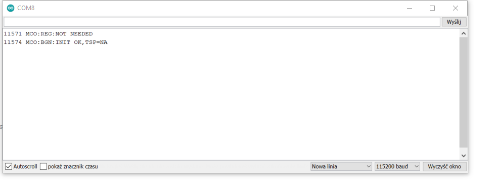
This is what i have:
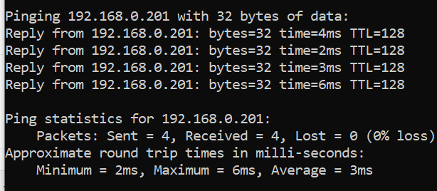
I cant see arduino in my router internal website, but i made a ping wrom Command line and i have this:
Unfortunatelly i cant connect it in HA:
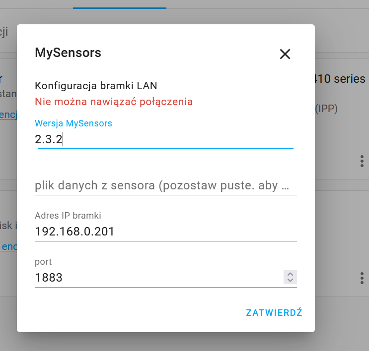
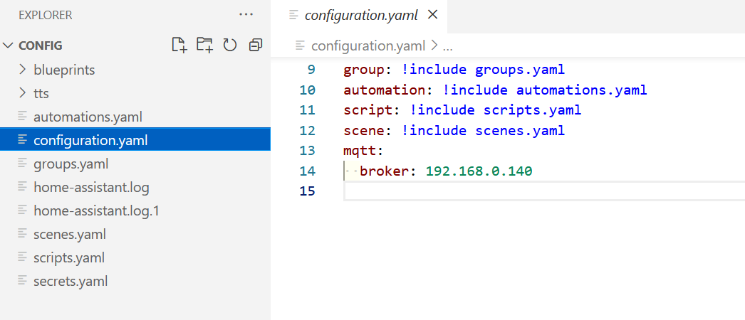
@PZDPRO I have never used HA but port 1883 in your configuration hints that HA is expecting a MQTT gateway. Your gateway is configured as an ethernet gateway. Therefore, the gateway does not support MQTT.
Either configure HA to use an MySensors ethernet gateway, or reconfigure your gateway to use MQTT. See https://www.mysensors.org/build/mqtt_gateway for instructions.
I think you'll need a MQTT broker as well. Instructions are available at https://www.mysensors.org/build/mqtt_gateway#setup-and-test-gateway
-
Thank you @mfalkvidd
Do i need this radio module even if i use wire system in my home?
-
@PZDPRO you only need the nrf24 if you want to connect sensor nodes to your gateway. See https://www.mysensors.org/about/network for details on how MySensors works.
@mfalkvidd OK.
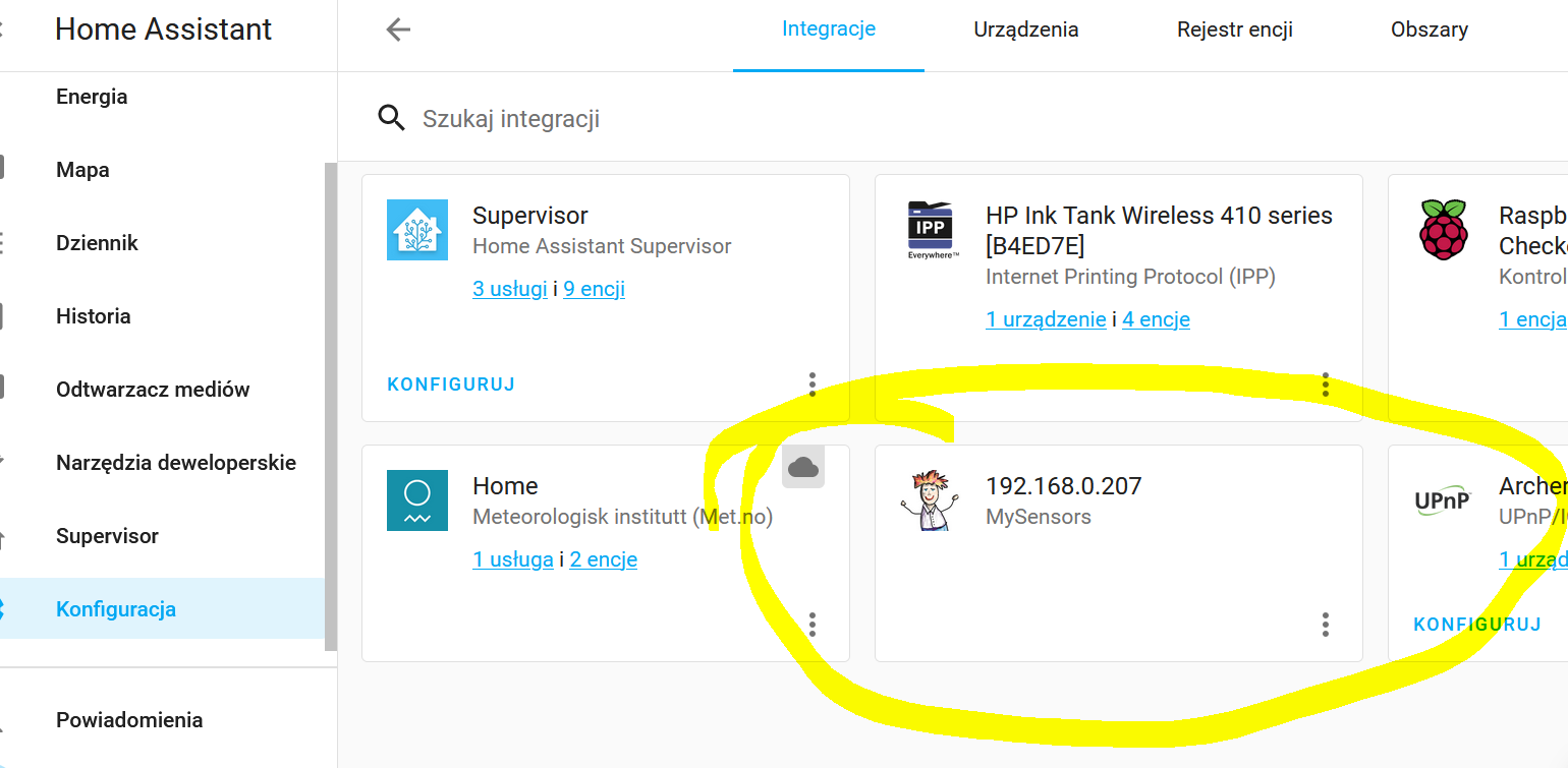
I changed my sketch and finally i connect it to HA using integration but still dont have any device in HA.
code_text // Enable debug prints to serial monitor #define MY_DEBUG // Enable and select radio type attached //#define MY_RADIO_RF24 //#define MY_RADIO_NRF5_ESB //#define MY_RADIO_RFM69 //#define MY_RADIO_RFM95 // Enable gateway ethernet module type #define MY_GATEWAY_W5100 // W5100 Ethernet module SPI enable (optional if using a shield/module that manages SPI_EN signal) //#define MY_W5100_SPI_EN 4 // Enable Soft SPI for NRF radio (note different radio wiring is required) // The W5100 ethernet module seems to have a hard time co-operate with // radio on the same spi bus. #if !defined(MY_W5100_SPI_EN) && !defined(ARDUINO_ARCH_SAMD) #define MY_SOFTSPI #define MY_SOFT_SPI_SCK_PIN 14 #define MY_SOFT_SPI_MISO_PIN 16 #define MY_SOFT_SPI_MOSI_PIN 15 #endif // When W5100 is connected we have to move CE/CSN pins for NRF radio #ifndef MY_RF24_CE_PIN #define MY_RF24_CE_PIN 5 #endif #ifndef MY_RF24_CS_PIN #define MY_RF24_CS_PIN 6 #endif // Enable UDP communication //#define MY_USE_UDP // If using UDP you need to set MY_CONTROLLER_IP_ADDRESS or MY_CONTROLLER_URL_ADDRESS below // Enable MY_IP_ADDRESS here if you want a static ip address (no DHCP) #define MY_IP_ADDRESS 192,168,0,207 // If using static ip you can define Gateway and Subnet address as well #define MY_IP_GATEWAY_ADDRESS 192,168,0,1 #define MY_IP_SUBNET_ADDRESS 255,255,255,0 // Renewal period if using DHCP //#define MY_IP_RENEWAL_INTERVAL 60000 // The port to keep open on node server mode / or port to contact in client mode #define MY_PORT 5003 // Controller ip address. Enables client mode (default is "server" mode). // Also enable this if MY_USE_UDP is used and you want sensor data sent somewhere. #define MY_CONTROLLER_IP_ADDRESS 192, 168, 0, 140 //#define MY_CONTROLLER_URL_ADDRESS "my.controller.org" // The MAC address can be anything you want but should be unique on your network. // Newer boards have a MAC address printed on the underside of the PCB, which you can (optionally) use. // Note that most of the Arduino examples use "DEAD BEEF FEED" for the MAC address. #define MY_MAC_ADDRESS 0xDE, 0xAD, 0xBE, 0xEF, 0xFE, 0xED // Enable inclusion mode #define MY_INCLUSION_MODE_FEATURE // Enable Inclusion mode button on gateway //#define MY_INCLUSION_BUTTON_FEATURE // Set inclusion mode duration (in seconds) #define MY_INCLUSION_MODE_DURATION 60 // Digital pin used for inclusion mode button //#define MY_INCLUSION_MODE_BUTTON_PIN 3 // Set blinking period #define MY_DEFAULT_LED_BLINK_PERIOD 300 // Flash leds on rx/tx/err // Uncomment to override default HW configurations //#define MY_DEFAULT_ERR_LED_PIN 7 // Error led pin //#define MY_DEFAULT_RX_LED_PIN 8 // Receive led pin //#define MY_DEFAULT_TX_LED_PIN 9 // Transmit led pin #if defined(MY_USE_UDP) #include <EthernetUdp.h> #endif #include <Ethernet.h> #include <MySensors.h> #include <Bounce2.h> #define MY_REPEATER_FEATURE #define MY_NODE_ID 1 #include <SPI.h> // Enable repeater functionality for this node #define MY_REPEATER_FEATURE #define RELAY_PIN 5 #define BUTTON_PIN 3 #define CHILD_ID 1 #define RELAY_ON 1 #define RELAY_OFF 0 Bounce debouncer = Bounce(); bool state = false; bool initialValueSent = false; MyMessage msg(CHILD_ID, V_STATUS); void setup() { pinMode(BUTTON_PIN, INPUT_PULLUP); debouncer.attach(BUTTON_PIN); debouncer.interval(10); // Make sure relays are off when starting up digitalWrite(RELAY_PIN, RELAY_OFF); pinMode(RELAY_PIN, OUTPUT); } void presentation() { sendSketchInfo("Relay+button", "1.0"); present(CHILD_ID, S_BINARY); } void loop() { if (!initialValueSent) { Serial.println("Sending initial value"); send(msg.set(state?RELAY_ON:RELAY_OFF)); Serial.println("Requesting initial value from controller"); request(CHILD_ID, V_STATUS); wait(2000, C_SET, V_STATUS); } if (debouncer.update()) { if (debouncer.read()==LOW) { state = !state; // Send new state and request ack back send(msg.set(state?RELAY_ON:RELAY_OFF), true); } } } void receive(const MyMessage &message) { if (message.isAck()) { Serial.println("This is an ack from gateway"); } if (message.type == V_STATUS) { if (!initialValueSent) { Serial.println("Receiving initial value from controller"); initialValueSent = true; } // Change relay state state = (bool)message.getInt(); digitalWrite(RELAY_PIN, state?RELAY_ON:RELAY_OFF); send(msg.set(state?RELAY_ON:RELAY_OFF)); } } -
@mfalkvidd OK.
I changed my sketch and finally i connect it to HA using integration but still dont have any device in HA.
code_text // Enable debug prints to serial monitor #define MY_DEBUG // Enable and select radio type attached //#define MY_RADIO_RF24 //#define MY_RADIO_NRF5_ESB //#define MY_RADIO_RFM69 //#define MY_RADIO_RFM95 // Enable gateway ethernet module type #define MY_GATEWAY_W5100 // W5100 Ethernet module SPI enable (optional if using a shield/module that manages SPI_EN signal) //#define MY_W5100_SPI_EN 4 // Enable Soft SPI for NRF radio (note different radio wiring is required) // The W5100 ethernet module seems to have a hard time co-operate with // radio on the same spi bus. #if !defined(MY_W5100_SPI_EN) && !defined(ARDUINO_ARCH_SAMD) #define MY_SOFTSPI #define MY_SOFT_SPI_SCK_PIN 14 #define MY_SOFT_SPI_MISO_PIN 16 #define MY_SOFT_SPI_MOSI_PIN 15 #endif // When W5100 is connected we have to move CE/CSN pins for NRF radio #ifndef MY_RF24_CE_PIN #define MY_RF24_CE_PIN 5 #endif #ifndef MY_RF24_CS_PIN #define MY_RF24_CS_PIN 6 #endif // Enable UDP communication //#define MY_USE_UDP // If using UDP you need to set MY_CONTROLLER_IP_ADDRESS or MY_CONTROLLER_URL_ADDRESS below // Enable MY_IP_ADDRESS here if you want a static ip address (no DHCP) #define MY_IP_ADDRESS 192,168,0,207 // If using static ip you can define Gateway and Subnet address as well #define MY_IP_GATEWAY_ADDRESS 192,168,0,1 #define MY_IP_SUBNET_ADDRESS 255,255,255,0 // Renewal period if using DHCP //#define MY_IP_RENEWAL_INTERVAL 60000 // The port to keep open on node server mode / or port to contact in client mode #define MY_PORT 5003 // Controller ip address. Enables client mode (default is "server" mode). // Also enable this if MY_USE_UDP is used and you want sensor data sent somewhere. #define MY_CONTROLLER_IP_ADDRESS 192, 168, 0, 140 //#define MY_CONTROLLER_URL_ADDRESS "my.controller.org" // The MAC address can be anything you want but should be unique on your network. // Newer boards have a MAC address printed on the underside of the PCB, which you can (optionally) use. // Note that most of the Arduino examples use "DEAD BEEF FEED" for the MAC address. #define MY_MAC_ADDRESS 0xDE, 0xAD, 0xBE, 0xEF, 0xFE, 0xED // Enable inclusion mode #define MY_INCLUSION_MODE_FEATURE // Enable Inclusion mode button on gateway //#define MY_INCLUSION_BUTTON_FEATURE // Set inclusion mode duration (in seconds) #define MY_INCLUSION_MODE_DURATION 60 // Digital pin used for inclusion mode button //#define MY_INCLUSION_MODE_BUTTON_PIN 3 // Set blinking period #define MY_DEFAULT_LED_BLINK_PERIOD 300 // Flash leds on rx/tx/err // Uncomment to override default HW configurations //#define MY_DEFAULT_ERR_LED_PIN 7 // Error led pin //#define MY_DEFAULT_RX_LED_PIN 8 // Receive led pin //#define MY_DEFAULT_TX_LED_PIN 9 // Transmit led pin #if defined(MY_USE_UDP) #include <EthernetUdp.h> #endif #include <Ethernet.h> #include <MySensors.h> #include <Bounce2.h> #define MY_REPEATER_FEATURE #define MY_NODE_ID 1 #include <SPI.h> // Enable repeater functionality for this node #define MY_REPEATER_FEATURE #define RELAY_PIN 5 #define BUTTON_PIN 3 #define CHILD_ID 1 #define RELAY_ON 1 #define RELAY_OFF 0 Bounce debouncer = Bounce(); bool state = false; bool initialValueSent = false; MyMessage msg(CHILD_ID, V_STATUS); void setup() { pinMode(BUTTON_PIN, INPUT_PULLUP); debouncer.attach(BUTTON_PIN); debouncer.interval(10); // Make sure relays are off when starting up digitalWrite(RELAY_PIN, RELAY_OFF); pinMode(RELAY_PIN, OUTPUT); } void presentation() { sendSketchInfo("Relay+button", "1.0"); present(CHILD_ID, S_BINARY); } void loop() { if (!initialValueSent) { Serial.println("Sending initial value"); send(msg.set(state?RELAY_ON:RELAY_OFF)); Serial.println("Requesting initial value from controller"); request(CHILD_ID, V_STATUS); wait(2000, C_SET, V_STATUS); } if (debouncer.update()) { if (debouncer.read()==LOW) { state = !state; // Send new state and request ack back send(msg.set(state?RELAY_ON:RELAY_OFF), true); } } } void receive(const MyMessage &message) { if (message.isAck()) { Serial.println("This is an ack from gateway"); } if (message.type == V_STATUS) { if (!initialValueSent) { Serial.println("Receiving initial value from controller"); initialValueSent = true; } // Change relay state state = (bool)message.getInt(); digitalWrite(RELAY_PIN, state?RELAY_ON:RELAY_OFF); send(msg.set(state?RELAY_ON:RELAY_OFF)); } }@PZDPRO
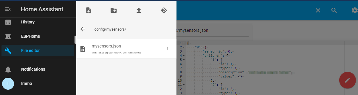
Hi, have you checked in HA the file /config/mysensors/mysensors.json?
Can you provide the content here?I have been using HA with MySensors for some time and it works for me, but sometimes HA behaves strangely for me too.
Maybe we can fix your problem here and maybe someone with more HA experience can join the discussion.So far your second Arduino sketch should work with HA.
BR Immo -
@PZDPRO
Hi, have you checked in HA the file /config/mysensors/mysensors.json?
Can you provide the content here?I have been using HA with MySensors for some time and it works for me, but sometimes HA behaves strangely for me too.
Maybe we can fix your problem here and maybe someone with more HA experience can join the discussion.So far your second Arduino sketch should work with HA.
BR Immo@virtualmkr Hello!
I checked and i think i dont have any file from mysensors.
I'm not good at programming and i only change ready skatches. Maybe you can be my guide how to start with this?
Main thing for me is to have arduino as a light controller. To analogs i have connected monostable switches and on digitals outputs a i had connected relays. In domoticz it works very well via USB. -
@virtualmkr Hello!
I checked and i think i dont have any file from mysensors.
I'm not good at programming and i only change ready skatches. Maybe you can be my guide how to start with this?
Main thing for me is to have arduino as a light controller. To analogs i have connected monostable switches and on digitals outputs a i had connected relays. In domoticz it works very well via USB.@PZDPRO
I use the File editor from Add-on Store:
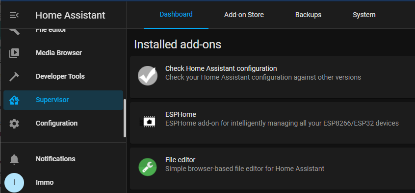
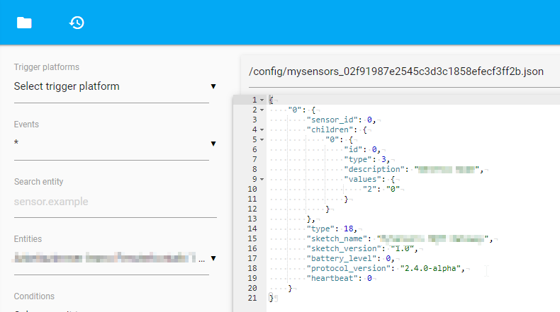
Then I can see the MySensors nodes configuration:
-
@PZDPRO
I use the File editor from Add-on Store:
Then I can see the MySensors nodes configuration:
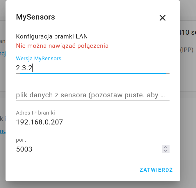
@virtualmkr
I cant connect to arduino again. I ping ip from my laptop and its ok.
Error in HA is "cannot make connection"
I installed file editor and i dont have such a folder and file. -
@virtualmkr
I cant connect to arduino again. I ping ip from my laptop and its ok.
Error in HA is "cannot make connection"
I installed file editor and i dont have such a folder and file.@PZDPRO It may be you use the automatic config file name. For me I have a second MySensors integration with the configuration file located directly in the config folder:
When your MyS gateway is reachable via ping then HA should be able to connect.
How is your HA hosted? Do you use the HA Raspi image?