Anyone using/tried the E28-2G4M27S 2.4Ghz LoRa SX1280 27dB module?
-
@NeverDie said in Anyone using/tried the E28-2G4M27S 2.4Ghz LoRa SX1280 27dB module?:
https://mcudude.github.io/MiniCore/package_MCUdude_MiniCore_index.json
It's very easy to use. You can install it into the regular Arduino IDE, pick from among the MiniCore "boards" in the board manager, select the 8Mhz option and a few other obvious options, and then you're done with instalation. From that point on your code will automagically compile using MiniCore. Just to be sure, I gave it a try myself, and I'm now blinking a blue LED off of Ardino Pin 20. It works!I leave this post as a reminder to anyone else reading this thread. The MCUDude link and installation step is VERY important. To install in the Arduino IDE add the link in File/Preferences/Additional Board Manager URLs; go to Board Manager and filter on minicore, click on Install when MiniCore comes up. Next when selecting the MiniCore board, make sure to select Clock as Internal (8 MHz), or avrdude won't be able to find your board. I went with the other board manager defaults and ... WaLa... my new barebones board is blinking on both pins 20 and 21. Overlooking, or not remembering, this May 14 post has cost me several weeks. So if you build yourself a barebones, heed this post.
@Larson
I suppose the design could be changed to include an optional diode on pin 13 for those who want to stay strictly orthodox Arduino.One could also allow a crystal oscillator to be installed, for those who want that as well, but I happen to think running from a crystal oscillator is generally a bad idea for a battery powered application, especially when the 8Mhz resonator seems to work so well.
-
@Larson
I suppose the design could be changed to include an optional diode on pin 13 for those who want to stay strictly orthodox Arduino.One could also allow a crystal oscillator to be installed, for those who want that as well, but I happen to think running from a crystal oscillator is generally a bad idea for a battery powered application, especially when the 8Mhz resonator seems to work so well.
@NeverDie said in Anyone using/tried the E28-2G4M27S 2.4Ghz LoRa SX1280 27dB module?:
...but I happen to think running from a crystal oscillator is generally a bad idea for a battery powered application...
No, don't change the design. I think you have a platform with a specific low power intent - including the education of others (like me). Matter of fact, I've got several battery projects that would be FAR better by changing to the on-chip clock, and new core. And so far, we are only using the 8 MHz setting. In the MiniCore the choices go to 1 MHz.
Back when I was... on PIC's... I bought 32 KHz crystals to minimize power. I just didn't know enough to use them and I still don't. But I'm working that direction and you have helped A BUNCH including you're idea of friends sitting around the table exchanging bits and bytes in a MISO/MOSI/SCK kind of way. I'm gathering that if you have control of the clock, you could have it all.
Besides you, Kevin Darrah, and Felix @ LowPowerLabs have also made great contributions to the low-power idea. I just haven't dedicated enough energy, yet, to their efforts.
16 MHz is impractically fast when so many designs just need low power.
I wanna go back to school,
DogWithA_Bone -
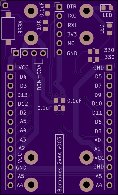
Here are the pin labels for the V001 barebones board for mounting on headers. The document I prepared for this wouldn't upload, but had nice lefthand/righthand orientations. This made it easier than having to open the CAD file everytime I needed to make connections.
But here is what I did in MS Word:
Turn on grid set spacing to 0.1"
Turn on ruler
Copy the below text
Align to the right or left as you wish
Font Calibri 5.5
Verify spacing (14 pins = 1.4")
PrintI also made columns and multiple copies of the below with both alignments. I have two boards built. Maybe you have more. Hope it helps.
GND
D5
D7
D9
D10/SS
D11/MOSI
D6
D8
A0
A1
VCC
GND
A5/SCL
A4/SDAVCC
D4
D3
D13/SCK
D12/MISO
D2/INTO
A5/SCL
A4/SDA
A3
A2
VCC
GND
A5/SCL
A4/SDADTR
RXTX
TXRX
VCC
X
GND[8/6/22 edit: reversed TX and RX as noted above - just incase someone has use for it]
-
@NeverDie Yea, I think I knew you upversioned the silkscreen. I think I remember you commenting on it. Looks pretty. BUT in my effort to add to the community, since I typed it for my self for my V001 boards, I thought I'd share it incase there is anybody like me with V001.
I like the V003 upgrades, specially that reset bypass via as discussed with @alphaHotel . Maybe I'll try it. I've got so much into my little V001's (yours actually) that I just can't give-em up. When I get the boards rigged up with radios, GPS (on the USART bus) and SD Card reader (on the SPI bus with a different CS), I'll shoot and send a picture in the spirit of a party!
-
@NeverDie today I re-read the fcc rules and I may have mislead you back in https://forum.mysensors.org/post/111853
It seems like the fcc rules say that if you use more than 500kHz bandwidth, you don't need to use frequency hopping, and there is no dwell time requirement.
(2) Systems using digital modulation techniques may operate in the 902-928 MHz, 2400-2483.5 MHz, and 5725-5850 MHz bands. The minimum 6 dB bandwidth shall be at least 500 kHz.
I don't understand why fcc encourages applications to hog a big portion of the spectrum but it looks like you can go willy-nilly if you just use enough bandwidth.
-
2.4GHz LoRa modules offer a good data rate compared to lower frequency ones that are very limited on this aspect, but they suffer path loss much more and wide use of 2.4GHz increase interference problem a lot.
I'm interested to know how they perform in typical urban use scenarios.
Has someone tested E28-2G4M27S in urban environment?
I have found only test result of people in very good condition as line of sight with no buildings or other obstacle interposed or at very short range (from a room to another in same building). -
@NeverDie I have noticed that in the latest version of your adapter you have lowered the capacitor value used for the first stage filtering from 100uF to 10uF, leaving the second stage one to 0.1uF. Did you have empirical benefit in tests with this configuration? 0.1uF it seems to me at first glance too small to accommodate current draw fluctuation of this module. Would be appreciated if you explain your design choice. Thank you.
-
@NeverDie I have noticed that in the latest version of your adapter you have lowered the capacitor value used for the first stage filtering from 100uF to 10uF, leaving the second stage one to 0.1uF. Did you have empirical benefit in tests with this configuration? 0.1uF it seems to me at first glance too small to accommodate current draw fluctuation of this module. Would be appreciated if you explain your design choice. Thank you.
@SMH17 said in Anyone using/tried the E28-2G4M27S 2.4Ghz LoRa SX1280 27dB module?:
@NeverDie I have noticed that in the latest version of your adapter you have lowered the capacitor value used for the first stage filtering from 100uF to 10uF, leaving the second stage one to 0.1uF. Did you have empirical benefit in tests with this configuration? 0.1uF it seems to me at first glance too small to accommodate current draw fluctuation of this module. Would be appreciated if you explain your design choice. Thank you.
The 10uF isn't for filtering. It's just to prevent voltage droop at the radio when the radio starts to pull current. So, yes, testing reveals that it seems adequate for that purpose. I originally slotted in 100uF because I wasn't sure, and overkill is better than underkill. It's possible that 10uF may also be overkill....
-
@haxn2 I don't recall there being any problems of the type you describe. You didn't say what kind of "trouble" you were having, but, if anything, the high coding factor and narrow bandwidth should improve range, unless there is interference in the narrower band. Have you tried changing the frequency? Are you sure you're using a suitable antenna? Exactly what kind of range are you trying to achieve?
-
-
@haxn2 https://github.com/jgromes/RadioLib/issues/388 might be useful
^^^This. Good point. Maybe do some testing with RadioLib to see whether or not you experience the same problem.