Anyone using/tried the E28-2G4M27S 2.4Ghz LoRa SX1280 27dB module?
-
Reporting back: it turns out that the trace antennas are highly directional, and changing the orientation on just one of them can remove 20 to 30dBa from the link budget, which is significant. I'm not sure why that is, as ESP8266's have a similar design and yet don't seem to be as sensitive to orientation. Therefore, putting an omni directiona antenna on at least the receiving node would seem to make a lot of sense.
Furthermore, the default settings used by the library appear to yield a link budget of just 123dB:
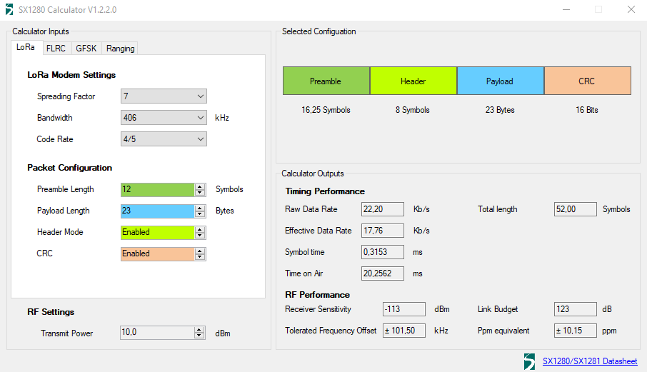
which is good for a meh transceiver, but not especially awesome for a LoRa transceiver. With such a meh link budget, it's easy to see how a poorly orientated trace antenna could severely impair the packet error rate.However, by increasing the spreading factor to 12 and narrowing the bandwidth to 200khz, it's possible to add roughly another 20dB to the link budget:
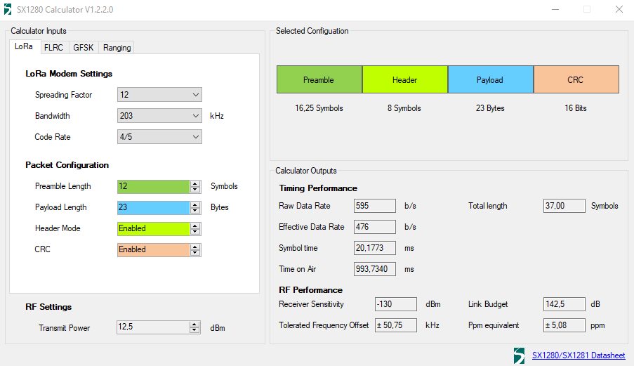
However, a big downside to this approach is that the transmission time incrases to nearly 1 second, which is a considerable energy drain. Also, the calculator only allows a max transmission power of 12.5dBm, which is well become the module;s advertised maximum transmit power. So,it has me wondering now whether some other register or pin needs to be touched in order to arrive at maximum transmission power. Presumably the SX1280 chip itself has a maximum transmit power of 12.5dBm, and further power would come from activating a power-amplifier on the module, similar to the way the RFM69 module works. However, looking at the manual, this is not the case. Rather, it appears that both the PA and the LNA are permanently activated, and it recommends setting the output power of the SX1280 to 0dBm, at which time the effective output power is 27dBm.So, I do that, and increase the spreading factor to 12, and decrease the bandwidth to 203kHz, but the overall performance is still lackluster. That the power output doesn't seem to be obviously easy to adjust is a disappointment. Overall performance falls far below what the 400Mhz AI-Thinker module can achieve, and those modules are very inexpensive (around $1-2 each).
So.... I'm disappointed. They perform far worse than even the el cheapo NRF24L01 modules that are outfitted with PA + LNA, which operate in the same 2.4Ghz band. This should not be! I'll try them next with some 2.4Ghz pigtail dipole antennas and see whether or not that yields significant improvement, even though it undermines the economics of choosing these modules in the first place. If that also fails, then I'm not sure it's worth the time, money, and effort to troubleshoot it further, especially since Andreas Spiess also wasn't sanguine about his different model 2.4Ghz Ebyte LoRa module either.
The nice thing about the Ai-Thinker LoRa modules is that they very easily accomodate a wire whip antenna (which are super cheap), whereas these Ebyte modules rely on either the trace antenna (which I now know to be problematic because of its apparent directional sensitivity) or on an IPEX connector, which increases the BOM's antenna price.
[Edit: I've changed out the power supplies for battery power. No change. I've removed the receiver from the PC, and no change either. Therefore, it either is the antenna, the breadboard wiring, the Ebyte module itself which is at fault, or else interference in the 2.4Ghz band is too much for these LoRa modules to handle (which would be weird, because 2.4Ghz Wi-Fi seems to work well enough, so go figure). I should receive some IPEX antennas this Thursday to try out, and if that doesn't solve it, then I'm going to build something equivalent with RA-01SH 915Mhz LoRa modules by AI-Thinker and see if that breadboard setup is dramatically better or not. Those modules cost around $3 each on Aliexpress ].
-
Reporting back: it turns out that the trace antennas are highly directional, and changing the orientation on just one of them can remove 20 to 30dBa from the link budget, which is significant. I'm not sure why that is, as ESP8266's have a similar design and yet don't seem to be as sensitive to orientation. Therefore, putting an omni directiona antenna on at least the receiving node would seem to make a lot of sense.
Furthermore, the default settings used by the library appear to yield a link budget of just 123dB:
which is good for a meh transceiver, but not especially awesome for a LoRa transceiver. With such a meh link budget, it's easy to see how a poorly orientated trace antenna could severely impair the packet error rate.However, by increasing the spreading factor to 12 and narrowing the bandwidth to 200khz, it's possible to add roughly another 20dB to the link budget:
However, a big downside to this approach is that the transmission time incrases to nearly 1 second, which is a considerable energy drain. Also, the calculator only allows a max transmission power of 12.5dBm, which is well become the module;s advertised maximum transmit power. So,it has me wondering now whether some other register or pin needs to be touched in order to arrive at maximum transmission power. Presumably the SX1280 chip itself has a maximum transmit power of 12.5dBm, and further power would come from activating a power-amplifier on the module, similar to the way the RFM69 module works. However, looking at the manual, this is not the case. Rather, it appears that both the PA and the LNA are permanently activated, and it recommends setting the output power of the SX1280 to 0dBm, at which time the effective output power is 27dBm.So, I do that, and increase the spreading factor to 12, and decrease the bandwidth to 203kHz, but the overall performance is still lackluster. That the power output doesn't seem to be obviously easy to adjust is a disappointment. Overall performance falls far below what the 400Mhz AI-Thinker module can achieve, and those modules are very inexpensive (around $1-2 each).
So.... I'm disappointed. They perform far worse than even the el cheapo NRF24L01 modules that are outfitted with PA + LNA, which operate in the same 2.4Ghz band. This should not be! I'll try them next with some 2.4Ghz pigtail dipole antennas and see whether or not that yields significant improvement, even though it undermines the economics of choosing these modules in the first place. If that also fails, then I'm not sure it's worth the time, money, and effort to troubleshoot it further, especially since Andreas Spiess also wasn't sanguine about his different model 2.4Ghz Ebyte LoRa module either.
The nice thing about the Ai-Thinker LoRa modules is that they very easily accomodate a wire whip antenna (which are super cheap), whereas these Ebyte modules rely on either the trace antenna (which I now know to be problematic because of its apparent directional sensitivity) or on an IPEX connector, which increases the BOM's antenna price.
[Edit: I've changed out the power supplies for battery power. No change. I've removed the receiver from the PC, and no change either. Therefore, it either is the antenna, the breadboard wiring, the Ebyte module itself which is at fault, or else interference in the 2.4Ghz band is too much for these LoRa modules to handle (which would be weird, because 2.4Ghz Wi-Fi seems to work well enough, so go figure). I should receive some IPEX antennas this Thursday to try out, and if that doesn't solve it, then I'm going to build something equivalent with RA-01SH 915Mhz LoRa modules by AI-Thinker and see if that breadboard setup is dramatically better or not. Those modules cost around $3 each on Aliexpress ].
-
@NeverDie in addition to the energy drain, the module would be transmitting for longer than the 400ms FCC dwell time limit.
@mfalkvidd Good catch! I'll take your word for it. Thank you!
Reporting back: I found a critical error. The library defaults to leaving the TX_EN and RX_EN pins disconnected. However, this module has a PA and LNA, so it is relevant to it. Since my first attempt merely followed the wiring instructions in the library, I had failed to enable these pins. Now that I have, it's a big improvement.
-
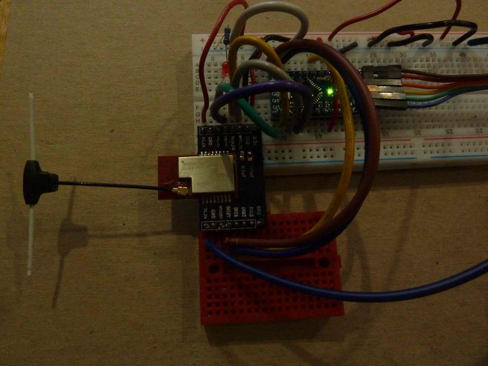
Thanks to feedback from @mfalkvidd, I've constructed this as the new target:
The directional sensitivity of the trace antenna is still a problem, so it'll have to wait until this Thursday, when the dipole antenna drives, to see whether the latest revision will be good enough or not.
-
Thanks to feedback from @mfalkvidd, I've constructed this as the new target:
The directional sensitivity of the trace antenna is still a problem, so it'll have to wait until this Thursday, when the dipole antenna drives, to see whether the latest revision will be good enough or not.
@NeverDie I am unable to find a better FCC reference than https://lowpowerlab.com/forum/rf-range-antennas-rfm69-library/fcc-rules-for-frequency-hopping/msg16006/?PHPSESSID=6e7efa8daee6de15d09c2b954879be34#msg16006 but that reference says:
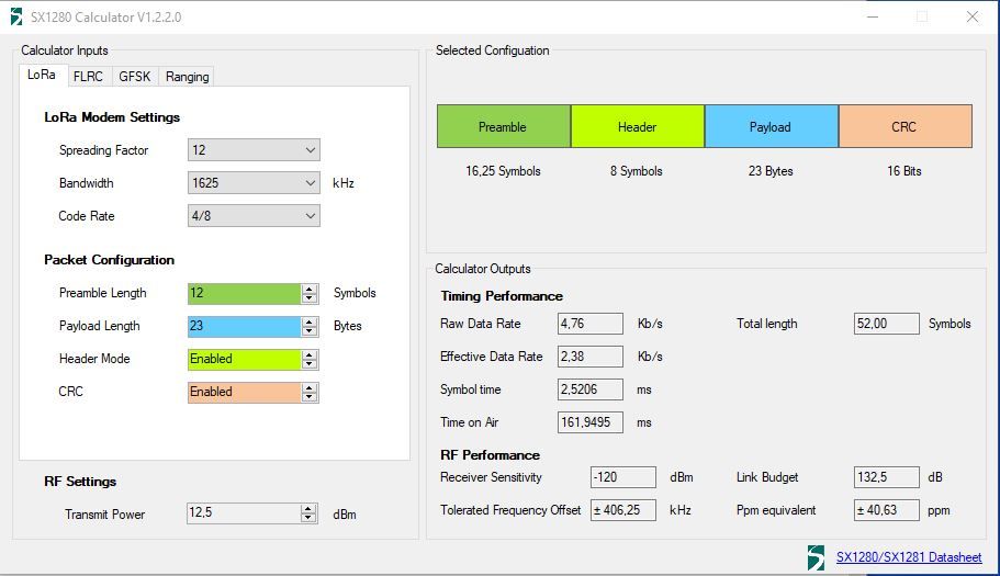
The maximum allowed 20 dB bandwidth of the hopping channel is 500 kHz.
Since the module is now using 1,625 kHz bandwidth, it is again outside FCC rules.
-
https://www.govinfo.gov/content/pkg/CFR-2013-title47-vol1/pdf/CFR-2013-title47-vol1-sec15-247.pdf seems to be a pretty good reference.
@mfalkvidd How about this then?
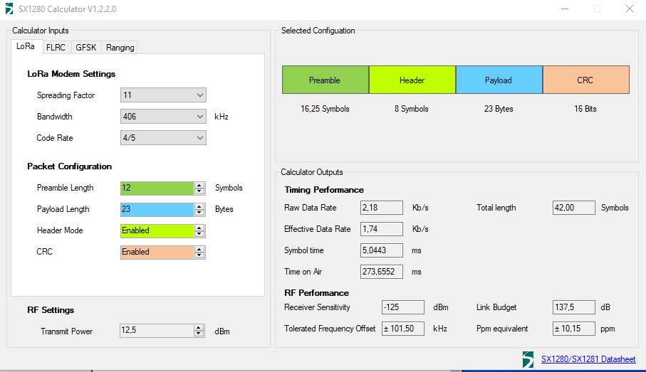
I'm spitballing this. If anyone has a better idea, or a correction, please do post!
-
@mfalkvidd How about this then?
I'm spitballing this. If anyone has a better idea, or a correction, please do post!
-
I found an IPEX to SMA adapter, and so I changed the antenna selector to select the soldered on IPEX connector and then borrowed an antenna from an unused wifi base station and connected it to the Ebyte module, like so, just to see if it would work at all.
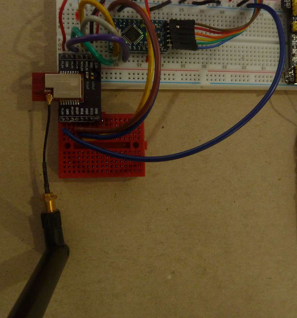
Doing this yielded a big improvement in Link Budget. Doing the same type of conversion on the LoRa transmitter module should make a noticeable difference, though I'm doubtful as to whether it will make enough of an improvement that it will perform as well as my AI-Thinker LoRa modules. Nonetheless, I'll attempt another, different, antenna hookup tomorrow when more antenna parts arrive from Amazon, and after testing it, I'll endeavor to reach a final conclusion.
Chasing down all these loose ends has been tedious, so if anyone finds this blog useful, please leave a thumbs-up to this posting. so that I know I'm not wasting my time writing it all down. At the moment I'm liking my AI-Thinker LoRa modules better: they have much better range and without all this fanfare they seem to "just work" straight out of the box.
-
It turns out Ebyte is kind enough to recommend specific antennas to use with this LoRa module:
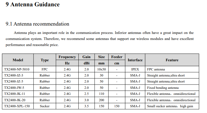
Unfortunately, these recommended antenna antenna models do not appear to be stocked by either Amazon or Mouser. Instead, it appears you may have to order them fromAliexpress:
https://www.ebyte.com/en/product-class.html?key=tx2400 So, your best bet would be to order the Ebyte antennas at the same time you order your Ebyte LoRa modules. Unfortunately, I didn't, and I'm now getting the distinct impression that ordering suitable antennas from Amazon is a crapshoot, because I've found supposedly different dipole antennas, but with the exact same dimensions, being marketed for both the 915Mhz band and for the 2.4Ghz band. Surely that can't be right?! :face_with_rolling_eyes: -
This is, allegedly, one of the TX2400-JW-5 antenna's that Ebyte recommends:
https://www.aliexpress.com/item/1005003096039403.html?spm=a2g0o.cart.0.0.63133c00YzHVcW&mp=1and this, it looks to me, is probably the same antenna, available on amazon:
https://www.amazon.com/gp/product/B093BVNPBW/ref=ppx_yo_dt_b_asin_title_o04_s00?ie=UTF8&th=1and which I'll be testing whenever it finally arrives from amazon (sometime soon). That way I'll be testing within manufacturer guidelines.
-
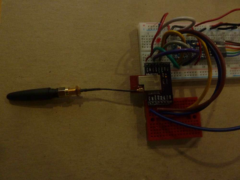
Reporting back: I first tried a dipole antenna bought on amazon (link above) that was allegedly for 2.4ghz:
I put this on both the transmitter and the receiver. The good news is that the IPEX connector made a very snug fit with the EBYTE module, but the bad news is that the results were terrible:5s Hello World 1234567890*,CRC,DAAB,RSSI,-81dBm,SNR,-2dB,Length,23,Packets,1,Errors,0,IRQreg,8012 8s Hello World 1234567890*,CRC,DAAB,RSSI,-87dBm,SNR,-18dB,Length,23,Packets,2,Errors,0,IRQreg,8012 10s PacketError,RSSI,-78dBm,SNR,-20dB,Length,23,Packets,2,Errors,1,IRQreg,8052,IRQ_RX_DONE,IRQ_HEADER_VALID,IRQ_CRC_ERROR,IRQ_PREAMBLE_DETECTED 13s PacketError,RSSI,-78dBm,SNR,-14dB,Length,23,Packets,2,Errors,2,IRQreg,8052,IRQ_RX_DONE,IRQ_HEADER_VALID,IRQ_CRC_ERROR,IRQ_PREAMBLE_DETECTED 15s Hello World 1234567890*,CRC,DAAB,RSSI,-87dBm,SNR,-16dB,Length,23,Packets,3,Errors,2,IRQreg,8012 18s PacketError,RSSI,-80dBm,SNR,-7dB,Length,23,Packets,3,Errors,3,IRQreg,8052,IRQ_RX_DONE,IRQ_HEADER_VALID,IRQ_CRC_ERROR,IRQ_PREAMBLE_DETECTED 32s PacketError,RSSI,-80dBm,SNR,-14dB,Length,23,Packets,3,Errors,4,IRQreg,8052,IRQ_RX_DONE,IRQ_HEADER_VALID,IRQ_CRC_ERROR,IRQ_PREAMBLE_DETECTED 40s PacketError,RSSI,-85dBm,SNR,-21dB,Length,23,Packets,3,Errors,5,IRQreg,8052,IRQ_RX_DONE,IRQ_HEADER_VALID,IRQ_CRC_ERROR,IRQ_PREAMBLE_DETECTED 41s PacketError,RSSI,-86dBm,SNR,-17dB,Length,23,Packets,3,Errors,6,IRQreg,8052,IRQ_RX_DONE,IRQ_HEADER_VALID,IRQ_CRC_ERROR,IRQ_PREAMBLE_DETECTED 101s RXTimeout 106s PacketError,RSSI,-72dBm,SNR,-12dB,Length,23,Packets,3,Errors,7,IRQreg,8052,IRQ_RX_DONE,IRQ_HEADER_VALID,IRQ_CRC_ERROR,IRQ_PREAMBLE_DETECTED 114s PacketError,RSSI,-75dBm,SNR,-11dB,Length,23,Packets,3,Errors,8,IRQreg,8052,IRQ_RX_DONE,IRQ_HEADER_VALID,IRQ_CRC_ERROR,IRQ_PREAMBLE_DETECTED 116s PacketError,RSSI,-76dBm,SNR,-11dB,Length,23,Packets,3,Errors,9,IRQreg,8052,IRQ_RX_DONE,IRQ_HEADER_VALID,IRQ_CRC_ERROR,IRQ_PREAMBLE_DETECTEDSo, time to finally try the factory recommended antenna (also linked above). Unfortunately, the IPEX to SMA adapter I got was the wrong kind (female SMA instead of male SMA), so I had to fall back onto the only one Ipex-to-male-sma adapter I had. So, I put that on the receiver and left the transmitter with the dubious dipole antenna:
More bad news was that the IPEX connector on this adapter made a rather loosey-goosey connection to the Ebyte module. How can that be? Are there different sizes/types of IPEX connectors or something? But, I went with it anyway because it's all I have at the moment, and the good news is that the result was tangible improvement:4s Hello World 1234567890*,CRC,DAAB,RSSI,-67dBm,SNR,-3dB,Length,23,Packets,1,Errors,0,IRQreg,8012 6s PacketError,RSSI,-67dBm,SNR,-2dB,Length,23,Packets,1,Errors,1,IRQreg,8052,IRQ_RX_DONE,IRQ_HEADER_VALID,IRQ_CRC_ERROR,IRQ_PREAMBLE_DETECTED 7s Hello World 1234567890*,CRC,DAAB,RSSI,-72dBm,SNR,-11dB,Length,23,Packets,2,Errors,1,IRQreg,8012 9s Hello World 1234567890*,CRC,DAAB,RSSI,-66dBm,SNR,-3dB,Length,23,Packets,3,Errors,1,IRQreg,8012 10s Hello World 1234567890*,CRC,DAAB,RSSI,-67dBm,SNR,-2dB,Length,23,Packets,4,Errors,1,IRQreg,8012 11s Hello World 1234567890*,CRC,DAAB,RSSI,-71dBm,SNR,-7dB,Length,23,Packets,5,Errors,1,IRQreg,8012 13s Hello World 1234567890*,CRC,DAAB,RSSI,-66dBm,SNR,2dB,Length,23,Packets,6,Errors,1,IRQreg,8012 15s PacketError,RSSI,-68dBm,SNR,-6dB,Length,23,Packets,6,Errors,2,IRQreg,8052,IRQ_RX_DONE,IRQ_HEADER_VALID,IRQ_CRC_ERROR,IRQ_PREAMBLE_DETECTED 18s Hello World 1234567890*,CRC,DAAB,RSSI,-66dBm,SNR,-5dB,Length,23,Packets,7,Errors,2,IRQreg,8012 19s PacketError,RSSI,-71dBm,SNR,-14dB,Length,23,Packets,7,Errors,3,IRQreg,8052,IRQ_RX_DONE,IRQ_HEADER_VALID,IRQ_CRC_ERROR,IRQ_PREAMBLE_DETECTED 20s Hello World 1234567890*,CRC,DAAB,RSSI,-64dBm,SNR,0dB,Length,23,Packets,8,Errors,3,IRQreg,8012 23s Hello World 1234567890*,CRC,DAAB,RSSI,-65dBm,SNR,0dB,Length,23,Packets,9,Errors,3,IRQreg,8012 25s Hello World 1234567890*,CRC,DAAB,RSSI,-66dBm,SNR,1dB,Length,23,Packets,10,Errors,3,IRQreg,8012 28s Hello World 1234567890*,CRC,DAAB,RSSI,-65dBm,SNR,-3dB,Length,23,Packets,11,Errors,3,IRQreg,8012 29s Hello World 1234567890*,CRC,DAAB,RSSI,-73dBm,SNR,-10dB,Length,23,Packets,12,Errors,3,IRQreg,8012 30s Hello World 1234567890*,CRC,DAAB,RSSI,-71dBm,SNR,-10dB,Length,23,Packets,13,Errors,3,IRQreg,8012 32s PacketError,RSSI,-66dBm,SNR,-15dB,Length,23,Packets,13,Errors,4,IRQreg,8052,IRQ_RX_DONE,IRQ_HEADER_VALID,IRQ_CRC_ERROR,IRQ_PREAMBLE_DETECTED 33s Hello World 1234567890*,CRC,DAAB,RSSI,-71dBm,SNR,-9dB,Length,23,Packets,14,Errors,4,IRQreg,8012 34s Hello World 1234567890*,CRC,DAAB,RSSI,-75dBm,SNR,-12dB,Length,23,Packets,15,Errors,4,IRQreg,8012 36s Hello World 1234567890*,CRC,DAAB,RSSI,-74dBm,SNR,-10dB,Length,23,Packets,16,Errors,4,IRQreg,8012 37s Hello World 1234567890*,CRC,DAAB,RSSI,-67dBm,SNR,-1dB,Length,23,Packets,17,Errors,4,IRQreg,8012 38s PacketError,RSSI,-72dBm,SNR,-20dB,Length,23,Packets,17,Errors,5,IRQreg,8052,IRQ_RX_DONE,IRQ_HEADER_VALID,IRQ_CRC_ERROR,IRQ_PREAMBLE_DETECTED 39s PacketError,RSSI,-68dBm,SNR,-5dB,Length,23,Packets,17,Errors,6,IRQreg,8052,IRQ_RX_DONE,IRQ_HEADER_VALID,IRQ_CRC_ERROR,IRQ_PREAMBLE_DETECTED 42s Hello World 1234567890*,CRC,DAAB,RSSI,-71dBm,SNR,-7dB,Length,23,Packets,18,Errors,6,IRQreg,8012What's immediately evident is a big improvement in both the RSSI and the SNR. Bear in mind that this improvement is with the factory recommended antenna on only the receiver module. The seemingly lousy dipole antenna is still on the transmitter module.
So.... next step is to order the right kind of IPEX to male SMA connector and see how it fares when the factory recommended antenna is connected to both the transmitter module and the receiver modules.
-
A related topic is: just what kind of component is the antenna selector anyway?
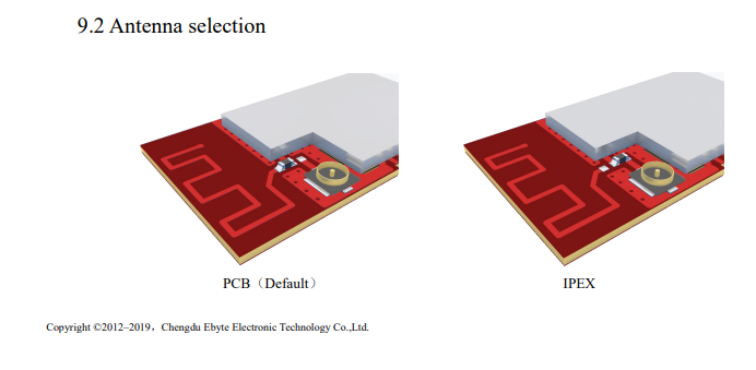
My measurements suggest it is just a zero ohm resistor. It's very tiny, however, which makes it difficult to desolder and then re-solder to the right pads when changing the selection. I did do that on the receiver module, but on the transmitter module I removed the selector component and then used a solder bridge to enable the IPEX antenna connector and disable the trace antenna. -
Reporting back: Answering my own question about the retention force on u.fl connectors, it turns out you may get only 5 connects/disconnects before the connector is shot and needs replacing. Source:
https://www.youtube.com/watch?v=naJvFB52EtcSo, I'm guessing that why the u.fl connector on only my u.fl to sma adapter cable became loosey-goosey, as I described above. Fortunately, at least according to this source, the u.fl connector on the PCB doesn't wear out. It's just the cable connector side that does.
-
Yes, the antenna selector is normally just a zero ohm resistor.
About the antenna sma connector: there are 4 connectors, not 2.
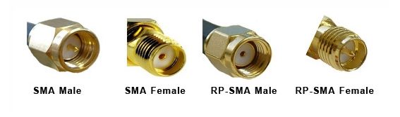
@mfalkvidd Thanks for that! So, it appears that what I need are the RP-SMA connectors, not the SMA connectors. All the wifi stuff is generally RP-SMA for instance. Yet another picture (duplicative of yours) to drive it home:

I had thought that maybe the threading was also different, but what I now gather that's not the case, as it wasn't needed to render the two standards incompatible. It's helpful to know that the RP-SMA standard was created for wifi, specifically so that wifi users wouldn't plug their wifi stuff into non-wifi stuff. Well, you potentially can, because the threading is the same, but you'll either get no joy from it or might even damage your connectors, because the inner connector will be the wrong gender. IMHO, they really should have changed the threading too as a further precaution and named it "reverse gender" instead of "reverse polarity", since polarity seemingly has nothing to do with it. i.e. the outer casing is ground in both standards, and the inner conductor is what carries the signal in both standards. But, they didn't, and now we have to live with it.Fun fact: what I was calling the number of "connect/disconnects" is technically referred to as the number of "mating cycles".
-
@mfalkvidd Thanks for that! So, it appears that what I need are the RP-SMA connectors, not the SMA connectors. All the wifi stuff is generally RP-SMA for instance. Yet another picture (duplicative of yours) to drive it home:
I had thought that maybe the threading was also different, but what I now gather that's not the case, as it wasn't needed to render the two standards incompatible. It's helpful to know that the RP-SMA standard was created for wifi, specifically so that wifi users wouldn't plug their wifi stuff into non-wifi stuff. Well, you potentially can, because the threading is the same, but you'll either get no joy from it or might even damage your connectors, because the inner connector will be the wrong gender. IMHO, they really should have changed the threading too as a further precaution and named it "reverse gender" instead of "reverse polarity", since polarity seemingly has nothing to do with it. i.e. the outer casing is ground in both standards, and the inner conductor is what carries the signal in both standards. But, they didn't, and now we have to live with it.Fun fact: what I was calling the number of "connect/disconnects" is technically referred to as the number of "mating cycles".
-
@NeverDie note that the picture you found has different naming for the RP variant than the picture I found.
RP-SMA male vs RP-SMA plug female socket
RP-SMA female vs RP-SMA jack male pinConfusion deluxe.
@mfalkvidd Good catch! I hadn't even noticed until you pointed it out. If even the people who make pictures meant to clarify are confused.....
-
@mfalkvidd Good catch! I hadn't even noticed until you pointed it out. If even the people who make pictures meant to clarify are confused.....
@NeverDie the rule I learned (which is not politically correct, but memorable) is that the male always does the screwing and if the male doesn't have a d**k it's reverse polarity.
The key here is to not focus on the signal connector, but on the mating. The female versions are fixed, the male versions screw on to the female.
-
@NeverDie the rule I learned (which is not politically correct, but memorable) is that the male always does the screwing and if the male doesn't have a d**k it's reverse polarity.
The key here is to not focus on the signal connector, but on the mating. The female versions are fixed, the male versions screw on to the female.
@mfalkvidd After checking just now what's for sale on amazon, your picture seems to be the right one. However, that phrase you have is bringing me to the wrong conclusion (the picture I posted). I mean, consider the RP-SMA female connector picture (referring to the picture you posted). You would think that would be male if anything is if that phrase was right. I mean, it screws "into" something else, and it has a d**k. Yet, evidently, its proper designation is female. Go figure.