Anyone using/tried the E28-2G4M27S 2.4Ghz LoRa SX1280 27dB module?


  • Hero Member

    CDEbyte had a sale, and I snapped up a bunch of them at $1.20 each (free shipping included!). Now I need to figure out what to do with them. I'm assuming that a generic SX1280 arduino library will interface to it, but I haven't dug into it at all. I'd like to set it up with the SHT45 TH sensor, which, as near as I can tell, seems like it will be the best temp-humidity sensor on the market when it releases (supposedly sometime this quarter): https://sensirion.com/products/catalog/SHT45/
    Highlights: 0.1C temperature acurracy, and 1% relative humidity accuracy, with a 0% to 100% range, and just a 0.4ua average current draw. I've acquired a bunch of precision tools that I'm going to keep in dry boxes to keep them from rusting, and my plan is to use this as a way to monitor and guarantee that the dry boxes are sufficiently dry, or else need a desiccant renewal. Although I was tempted to use commercial TH sensors, since they're so cheap these days, a LoRa/SHT45 sensor would likely be far more capable and hence worth the effort.


  • This is an interesting find, can you share the link? I can't find these low prices anywhere.


  • Hero Member

    @electrik Here:
    https://www.aliexpress.com/item/1005003897673336.html?spm=a2g0o.order_list.0.0.21ef1802o2L1ib

    I like that it has a PCB antenna built into it. That way I don't need some wire antenna sticking out of it, flapping in the breeze so to speak.

    Maybe they were just unloading their US inventory, for whatever reason. If it weren't for the crazy low price, I would have gone for the SX1260, which seems to be a newer, improved generation. That said, this guy was able to get a 40km range out of his 2.4ghz SX1280 module (some other brand of module) using just 4dB transmit power: https://github.com/StuartsProjects/SX1280_Testing
    so the SX1280 chip itself is no slouch. He estimates " a potential range of 80km LOS at 10dBm", and so my module, having 27dB, would presumably beat that handily if it were to use full power--which I have no intention of doing. Rather, just the opposite: with such a large link budget, I should be able to run it at extremely low Tx power in a domestic environment, probably below the noise floor even (a neat trick that LoRa is allegedly capable of doing). On the other hand, for those who are interested in joining up with the LoRaWAN community, the high transmit distance might be a strong selling point, especially in these early days when the nearest friendly node might be quite a distance away from you. The advantage of that, of course, is that it's free, and it might give you IoT backup connectivity for those brief occasions when your regular ISP goes down. Not sure how they keep freeriders out of the system, but maybe it's like torrents, where you build up credit in the community by taking other people's traffic when you can, and they in-turn reciprocate when you need it. Ideally, they'd have a different ISP, or, if not, can at least pass your traffic to someone else on the LoRaWAN who has a different ISP than you. If you were also running Amazon Sidewalk, then you'd have yet additional redundancy (but, that's a different topic entirely). All that said, with all the hacking going on, I really do like the idea of running below the noise floor--seems like yet another layer of security.


  • Hero Member

    For anyone who may be interested, I found a basic breakout board for this module here: https://easyeda.com/jbk1/e28-adapter
    It's nothing fancy, but I suppose you maybe get more ground plane than if you were to just solder on some castellated pins.
    You can download the gerber and then etch or fab however you want. It's a nice luxury when someone else has already done the work! In my case 3 boards from oshpark is probably the cheapest option to test out a simple ping-pong pair of transceivers to verify whether the available library software for it works (as I presume it will), with no extra cost to upgrade to 2oz copper. $7.10.

    Not sure what the SHT45 will be priced at. It's supposed to "release" sometime this quarter (i.e. before the end of March), but who knows how long it will take from then until it becomes available at mouser/digikey/arrow or wherever. I suppose I could live with the SHT41, which is about $4 per chip on mouser, quantity 1, and already in stock. I haven't yet checked, but with luck the SHT45 would be pin compatible for future builds down the road. If it really does on average draw only 0.4ua current, then maybe it could wakeup your MCU whenever there's a temp/RH change, which would maybe be nicer than waking up your MCU with a timer interrupt to poll the sensor to see if anything has changed.


  • @NeverDie said in Anyone using/tried the E28-2G4M27S 2.4Ghz LoRa SX1280 27dB module?:

    ey'd have a different ISP, or, if not, can at least pass your traffic to someone else on the LoRaWAN who has a different ISP than you. If you were also running Amazon Sidewalk, then you'

    @NeverDie. Thanks for your write-up. Before I lose my train of thought and go look at StuartsProjects I have to ask about the EasyEDA design: doesn't it make TX/RX much better with no groundplane around the antenna? I've just completed a 433 MHz project and found that I was better to get the TX side way off my groundplaned board. Also, I've noticed that other ESP8266 breakouts dutifully remove the groundplane from breakout boards that would be near the ESP's built-in PCB antenna.

    I don't know much about radio's so can easily accept any comment for the better, or even ridicule. I've learned as much as I can about radios from Andreas Spiess. He would simply test the difference with a RF sensor.


  • Hero Member

    @Larson Good catch! Yes, indeed, that breakout board will be no good for a trace antenna. Dang! I ordered it from oshpark on the assumption the designer knew what he was doing, but thanks to you I can now see that it's absolutely FUBAR. Because of that I'll have to use an external antenna with it. 😠 I suppose in theory I could scrape off that part of the ground plane which lay below the trace antenna.... Better yet, I'll completely saw off the top portion of the breakout board so that there's nothing below the trace antenna at all: alt text

    Thanks for pointing out that fatal flaw! I suppose it might be OK with an external antenna, but definitely not for a trace antenna without some post processing to fix it.


  • Hero Member

    Something I'm less sure about is that the author placed ground planes on both sides of the PCB:
    top.png
    bottom.png

    Even though the two ground planes are connected together with enough vias to make a colander, I do wonder whether this arrangement might introduce at least some amount of unanticipated capacitance. Anyone know? Is this best practice, or would it have been better to keep the ground plane on one side only?


  • @NeverDie. Thanks for the comment. I'm not sure if I've got that ground-plane radio interferance thing right. Maybe there is a SMD socket thing in which a radio could be clipped so you don't have to commit a radio to the board to find out. I've not seen one but I've not looked. Maybe it is time to invent one with springs to receive castellated edges. A jig like that would also serve ESP8266's. I like the PTH sockets for this kind of experimentation.
    The idea of sawing off the top just north of the TXEN/RXEN connections is good. Maybe you could do that after mounting so you could test before AND after. That would be definitive.
    On the other hand a redesign and reorder from OSHPark can't be that much of a setback. I really enjoy their service. They happen to be less than 5 miles from my home - but they ship globally. Small world.
    Let me know what you learn. I'll learn with you much as I have been doing with hundreds of your other posts - and I thank you.


  • Hero Member

    I recently purchased a Yolink gateway and some Yolong LoRa devices to go with it. For whatever reason, the radio link isn't rock solid--and, yes, I'm running the most curent firmware--whereas my DIY LoRa devices that I made years ago are totally rock solid. Hence, I still have reason to make my own LoRa circuits and firmware, even though I'd frankly prefer to just buy something off-the-shelf. It's these kind of shortfalls that led me into designing my own circuits in the first place. Perhaps it will be forever thus. 🙄


  • Hero Member

    Reporting back: it turns out that accurately sawing off the upper part of the PCB was one of those "easier said than done" type of things, so I'm starting over and creating my own E28-2G4M27S breakout board in KiCAD from scratch. I wasn't a fan of KiCAD previously, but I'm finding KiCAD 6, which is the current release, is much improved! I'll post my breakout board here at mysensors after I've had it fabbed and validated that it is correct.

    The datasheet for E28-2G4M27S doesn't have dimensions which show exactly where the antenna traces start and end, so I'll measure that with a micrometer and use my own measurement for that to generate the silkscreen delimiter for that region and to ensure that the copper ground plane doesn't run beneath the trace antenna. I'll be deliberately over conservative so as to better ensure there's no overlap.


  • Hero Member

    Looking at the module itself:
    E28-2G4M27S.jpg
    I suppose one could maybe argue that the antenna chain starts just prior to where the IPX antenna connector sits, so I'll remove groundplane from anywhere to the left of it just to be sure. Looking at the above photo, that may(?) be overkill, as it looks as though for the IPX connector to be active the resistor would need to be removed and a solderbridge installed in order to make the IPX connector active. As I'm not entirely sure though, I'll simply assume a worst case scenario and then build to that.


  • Hero Member

    Good to know! I found this video which I think may answer to my earlier question above:

    [LIVE] How to Achieve Proper Grounding - Rick Hartley - Expert Live Training (US) – 2:19:51
    — Altium

    Basically, for high frequency communications, the return path in the ground plane is directly beneath the trace. For this reason, rule #1 is to never route across splits in the ground plane:
    neverRouteAcrossSplitsInGroundPlanes.png

    Therefore, for a two sided board, the ideal would be to have a prestine ground plane on the bottom layer. Adding another "ground plane" on the top layer is effectively an oxymoron. According to the presenter, routing across a split in the ground plane, as in the cut channel of case #2, can cause considerable EMI problems.


  • Hero Member

    Here's the breakout board for it that I just now made using KiCAD version 6: https://www.openhardware.io/view/8304/E28-2G4M27S-24GHz-LoRa-Breakout-Board
    IMHO, this breakout board should be much better than the breakout board done by the other guy that I referenced earlier in this thread.


  • @NeverDie : Thanks for the redesign and putting it on openhardware. If you do fab it at OSHPark, leave it open for others. I'll, for sure, pick-up a handfull.


  • @NeverDie - I gotta say the Rick Hartley video has been really helpful to understand ground planes. At about 14:00 he nails it: "the energy is in the field". When learning electric-magnetic force, I didn't think that the energy is in the field (i.e. magnetic). I only have 2 hours to go to learn more! Thank you.


  • @NeverDie Sorry to bother again... but I gotta say this Hartley traning video has been monumental. I always thought the world was divided into AC and DC. NOW, I think I get it: DC circuits flipping on and off at a SIGNAL frequency are actually AC just with a different voltage basis. The KEY, Hartley says, is that the energy is not in the trace, but in the field during the rise and fall of voltage. This is also helping me to finally understand inductance. WHY didn't they say this 40 years ago in school? Oh, perhaps I was sleeping as I did.
    This is a breakthrough that may lead me to understanding antennae theory and a bunch of other stuff. I thank you for the introduction. I gotta go find this Hartley fellow to thank him.


  • Hero Member

    @Larson Glad you liked it. If you're interested in the theory of it, then you may find this a worthwhile survey of some of the big ideas:
    The Big Misconception About Electricity – 14:48
    — Veritasium

    Plainly it's a deep topic, so I'm relieved whenever I find simple design rules of thumb which make it possible to do successful projects without having to peel back everything to first principles. 😉


  • @NeverDie Yes, I strive to not reinvent also. But it is nice to know why wheels are round. So I dug a little further on this ground plane subject and I’m conflicted. At 40:42 on this video, ground planes are discussed. In short, he discourages the use of ground planes. So I ask myself, what design is used on an ESP8266 itself. Certainly, they use the best design standards to minimize EMI since they manufacture these radios by the millions. To find out I get out my zacto knife and scrape off some of the masking of the ESP and check for ground. Sure enough they use ground planes everywhere except for under the antennae. Go figure.

    [Edit 5/30/22. After listening to the link in my post again, I’m realizing that I was wrong to say Eric Bogatin discourages ground planes. I think I’ve learned that he discourages the use of copper fills on signal layers. Big difference. It was unclear in the referenced video segment that the three experimental boards with different trace distributions had a ground plane below, but I believe that was the case.]


  • Hero Member

    @Larson AFAIK, the biggest reason to have a ground plane in a radio system is to improve the performance of a whip antenna. I'm not sure what's ideal, but, for example, https://www.digi.com/support/knowledge-base/does-a-1-4-wave-antenna-need-a-ground-plane recommends a 3 inch radius groundplane for a 2.4Ghz radio if the antenna were put in the very middle of it. Well,that would be a 6 inch diameter ground plane! Not a great option for tiny IOT devices.
    Fortunately, it does concede that "The antenna can still work on a smaller ground plane but the efficiency will be reduced." On the other hand, if you're using a dipole antenna, then maybe (?) the ground plane isn't so important. Not entirely sure.

    Anyhow, if you find out anything more, I'd be interested.


  • I'm an engineer, though not RF. My understanding, from short discussions years ago with RF engineers, was that the ground planes have strong effects on antenna performance.

    Depending on the design of the antenna, sometimes you want the ground plane and sometimes you don't.

    But that's the extent of what I remember. (And it could be that I've even got errors in that little bit.) But basically to go with whatever the antenna designer recommended, because there are reasons for it. Just because one design calls for it and the other doesn't, it doesn't make either of them wrong.

    Without the deep understanding myself, and not having however much testing equipment necessary to check the results, I try to stick as close to what the manufacturer/designer calls for as possible.


  • @NeverDie and @ejlane: Thanks for the inputs. Wise counsel has been my easy path, too, especially in engineering (Civil by profession, but wannabe Electronic in my retirement). @ejlane: I ran across NeverDie and MySensors in my earlier radio research (RFM69’s I think) and fast embraced his advice & learnings. And I admire his clear writings/descriptions.
    After digesting the content of this thread and having time to sleep on it I’m starting to think that signal integrity (EMI) and antennae performance are maybe the same thing on different ends of a design spectrum. So perhaps both ground planes and non-ground planes are just different design criteria for different purposes (transmission vs. noise immunity).

    @NeverDie - yep, 6-inch GP will sink my little boards. Funny that the RFM69's do so well with such a tiny board and whip antennae. I haven't scraped the masking on those radios looking for GP's, however.

    Someday I'll grow-up and buy a scope. Discussions like this really help – thanks.


  • I'd say that EMI is just transmitting accidentally. Parts of the circuit are radiating when you didn't mean them to. When that accidental radiation - which is unavoidable at some level - rises above the regulation limit for any frequency band then you have FCC (or other country alternative agency) problems. Of course the accidental emissions can also be just about any frequency, depending on trace length and shape, clock speeds, etc. That again might require antenna knowledge to know what to expect.


  • @NeverDie said in Anyone using/tried the E28-2G4M27S 2.4Ghz LoRa SX1280 27dB module?:

    Anyhow, if you find out anything more, I'd be interested.

    Eric Bogatin, master and professor of signal integrity, gave this presentation at an Altuim conference. At about 42:00 he talks about 7 Habits of Good Design. This, again, has more to do with PCB design and not radio performance. I have a suspicion that several radio boards I designed failed not because of the transmitter, but because of bad PCB design. I can make a failed transmitter (whip antennae) board work by putting the 433 MHz transmitter on a 7" leash away from the board. Now that is a sign.

    @ejlane - Thanks. I'm just now learning of the EMI/EMC testing required for commercial products and FCC requirements. While that exceeds the requirements and budget for my home projects, I do think that I might employ the pre EMI testing that one can do with a scope and probes. That may drive me back to school to learn scopes!


  • @Larson As far as I know, it takes special probes for magnetic fields to check for EMI. Never done it myself, but I keep meaning to. 🙂

    But scopes are well worth it to see what's going on. You can make it a fair ways with just fiddling with the dials and some light watching of YouTube. I used scopes a bit here and there before I ever went to school for engineering. (Though there was no YouTube to learn from at the time. The basics are pretty self-explanatory, and the advanced features are still beyond what I really do sometimes.)


  • Hero Member

    Good news. Regarding the SHT45 TH sensor I mentioned in the first post, mouser expects to have it in stock by July 29, 2022: https://www.mouser.com/c/?q=sht45 Quantity 1 price is $4.60. AFAIK, in terms of accuracy and precision and measurable range, it's pretty much state of the art. If anyone knows of anything better, please do post what it would be.

    A bit like the DeLorean in Back to the Future, I figure if you're going to build a TH sensor, might as well do it in style!


  • Hero Member

    I've had the board fabricated, and I've verified that the through-holes will correctly line-up with the holes on a 2.54 pitch prototypig board. Also, the landing pads appear to line-up perfectly as well. Therefore, I have removed the "work in progress" tag. The breakout board is done!
    built.jpg

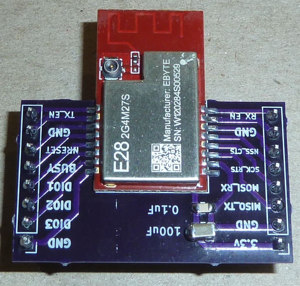
    https://www.openhardware.io/view/8304/EBYTE-E28-2G4M27S-SX-1280-chip-24GHz-LoRa-Breakout-Board


  • Hero Member

    I just now noticed that Andreas Spiess did a youtube about the same chip, though different model Ebyte modue:
    #323 Connected Light Sensor with 2 4GHz LoRa: How is its range? (SX1280, Arduino, ESP32) – 13:11
    — Andreas Spiess

    Small world: it turns out he also made a breakout board for himself in order to test the module. It doesn't look pin compatible with my module, however, as it has only 14 pins on its pinout, whereas mine has 16. Also, not sure whether Andreas posted his breakout board anywhere. I would expect so. He has a github, but it has almost no descriptive material in it other than the titles, so it's hard to know what is truly what.

    Worthy of note: the module he chose is less capable than the one I picked: substantially less potential transmit power, and also, according to Ebyte specs, somewhat inferior receive sensitivity.

    Fortunately, he does post links to the libraries that he used to operate the SX1280 chip, so that's probably a good starting point, or at least a point of comparison.

    To avoid interference he does report having to turn off the wifi on his esp32 that's driving the module, so having an ethernet connection for the gateway probably makes the most sense. The good news is that with LoRa, you should need only one such gateway, and you can probably put it just about anywhere and still have a good, solid RF connection to your nodes. Probably a raspberry pi could serve that purpose for a low effort solution, though I may go for an arduino-ethernet solution because that may turn out to be even easier, and probably without the need for ongoing updates and security maintenance. i.e. it should "just work". Perhaps setting the target IP address with a dipswitch would avoid any future need to revisit the firmware. Also, a raspberry pi's attack surface seems orders of magnitude larger than a more basic, hardware oriented solution.

    Regardless, the next step for me is to wire it up and get it to play ping pong with another node. Then I'll be able to quickly determine whether ambient wi-fi signals in the environment will be a cause for concern or not. I suspect not, but sending thousands/millions of test packets while measuring for packet loss will tell the tale definitively.

    I have one node with a 100uF capacitor (pictured in my preceding post), and another node without, so I'll try to determine whether it makes any practical difference or not. I'm guessing that it were powered by a coincell, it's essential, but if by two AA's in close proximity, probably not (though if the batteries are weak, maybe it would, at the margin, still help).


  • Hero Member

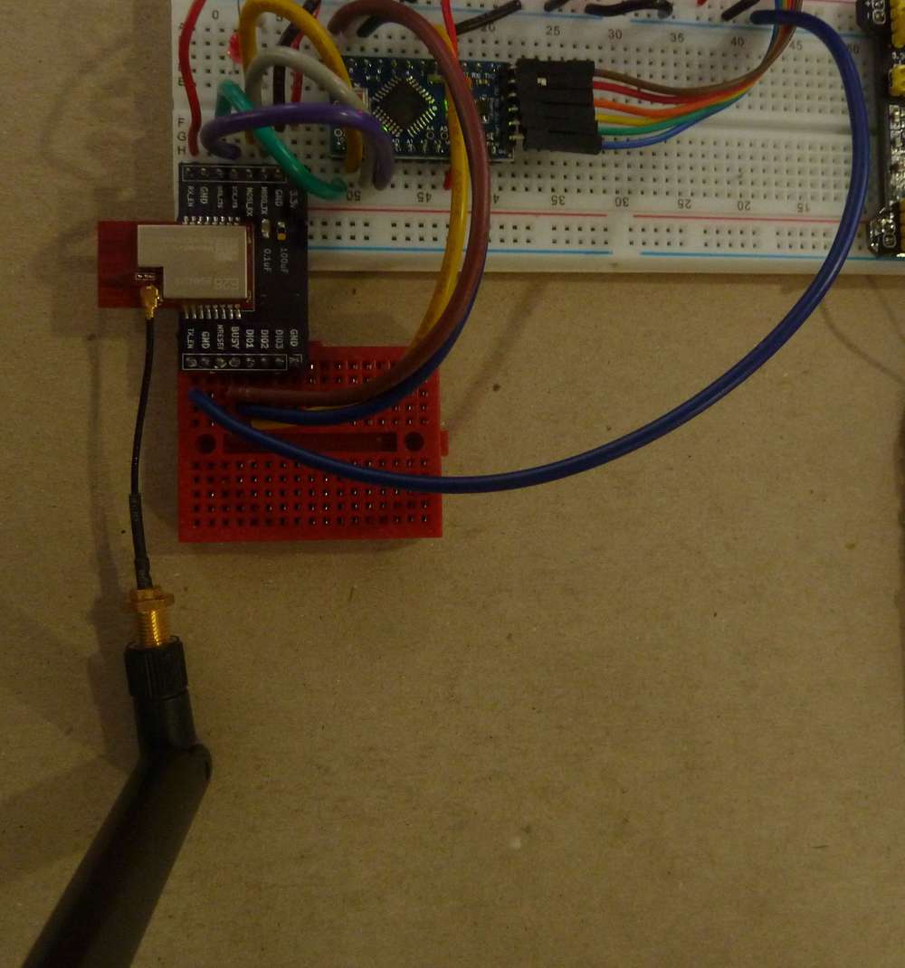
    Here's what the breadboarded LoRa transmitter node looks like:
    Tx_LoRa.jpg

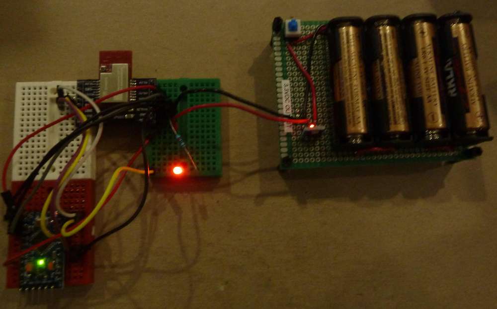
    It turns out you need an external LED for status purposes, because the typical Pin 13 LED isn't available because it's in use by the SPI interface as a clock pin. The LED blinks every time a packet is transmitted (about once a second). In the picture here, I managed to photograph it at the very moment of blinking after a transmission.

    The wiring pinout is given in the header file of the library example application, so no thinking required. I'm using a generic pro mini with the 5v LDO removed, and I then programmed it using the Arduino IDE as a 3.3v 8Mhz pro mini using the library's example transmitter setup sketch downloaded from: https://github.com/StuartsProjects/SX12XX-LoRa


  • Hero Member

    Here's what the breadboarded receiver looks like:
    Rx_LoRa.JPG

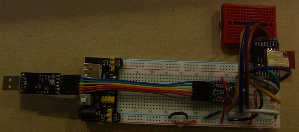
    Every time it receives a packet from the transmitter (pictured in the immediately preceding post), it blinks the red LED.

    Simple to assemble. Both transmitter and receiver worked flawlessly the very first time I put it all together. 🙂

    Next up: do range testing around the house and run enough packets to determine whether any ever get lost, and, if so, what the rate of loss is. I'll also dial down the transmit power to see how low is still sufficient.


  • @NeverDie - thanks for the prolific work. There is alot to consider here. I reviewd the Andreas Spiess video...wonderful as usual. I'll have lots of questions after I set-up my own station to poke around.

    On your range tests: The tests that I have seen that are most effective are those where the transmitters are always sending. The recievers have packet counting stats to give evidence. And for a topper, the reciever sends an ack that can also meausre packett success. Fun stuff.


  • Hero Member

    @Larson Yup. It will be fun to see how LoRa performs at 2.4Ghz.😁

    Since LoRa potentially has such long transmission windows (at the extreme, as much as one second), it will be important to keep the transmissions of different nodes from overlapping and for recovering (and avoiding future overlaps) if they do.


  • Hero Member

    In case anyone is wondering, the default receiver output using the library's receiver setup example looks like this:

    17:05:02 Apr 17 2022
    V1.0
    
    104_LoRa_Receiver_Detailed_Setup Starting
    
    LoRa Device found
    
    SX1280,PACKET_TYPE_LORA,2444999936hz,SF7,BW406250,CR4:5
    SX1280,PACKET_TYPE_LORA,Preamble_12,Explicit,PayloadL_255,CRC_ON,IQ_NORMAL,LNAgain_HighSensitivity
    
    Reg    0  1  2  3  4  5  6  7  8  9  A  B  C  D  E  F
    0x900  80 FF 77 41 20 FA BC 13 C1 80 00 00 00 00 00 61 
    0x910  9C 44 00 00 00 19 00 00 00 19 87 65 43 21 7F FF 
    0x920  FF FF FF 00 70 37 12 50 D0 80 00 C0 5F D2 8F 0A 
    0x930  00 C0 00 00 00 24 00 21 28 B0 30 0D 01 51 63 0C 
    0x940  58 0B 32 0A 16 24 6B 96 00 18 00 00 00 00 00 00 
    0x950  00 00 00 00 00 00 00 00 00 00 00 00 00 00 00 00 
    0x960  00 00 00 00 00 00 00 00 00 00 FF FF FF FF FF FF 
    0x970  FF FF FF FF FF FF FF FF FF FF FF FF FF FF FF 04 
    0x980  00 0B 18 70 00 00 00 4C 00 F0 64 00 00 00 00 00 
    0x990  00 00 00 00 00 00 00 00 00 00 00 00 00 00 00 00 
    0x9A0  00 08 EC B8 9D 8A E6 66 04 00 00 00 00 00 00 00 
    0x9B0  00 08 EC B8 9D 8A E6 66 04 00 00 00 00 00 00 00 
    0x9C0  00 16 00 3F E8 01 FF FF FF FF 5E 4D 25 10 55 55 
    0x9D0  55 55 55 55 55 55 55 55 55 55 55 55 55 00 00 00 
    0x9E0  00 00 00 00 00 00 00 00 00 00 00 00 00 00 00 00 
    0x9F0  00 00 00 00 00 00 00 00 00 00 00 00 00 00 00 00 
    
    
    Receiver ready - RXBUFFER_SIZE 32
    
    4s  Hello World 1234567890*,CRC,DAAB,RSSI,-51dBm,SNR,13dB,Length,23,Packets,1,Errors,0,IRQreg,8012
    5s  Hello World 1234567890*,CRC,DAAB,RSSI,-51dBm,SNR,13dB,Length,23,Packets,2,Errors,0,IRQreg,8012
    6s  Hello World 1234567890*,CRC,DAAB,RSSI,-51dBm,SNR,8dB,Length,23,Packets,3,Errors,0,IRQreg,8012
    7s  Hello World 1234567890*,CRC,DAAB,RSSI,-51dBm,SNR,13dB,Length,23,Packets,4,Errors,0,IRQreg,8012
    8s  Hello World 1234567890*,CRC,DAAB,RSSI,-52dBm,SNR,12dB,Length,23,Packets,5,Errors,0,IRQreg,8012
    9s  Hello World 1234567890*,CRC,DAAB,RSSI,-51dBm,SNR,14dB,Length,23,Packets,6,Errors,0,IRQreg,8012
    10s  Hello World 1234567890*,CRC,DAAB,RSSI,-51dBm,SNR,13dB,Length,23,Packets,7,Errors,0,IRQreg,8012
    11s  Hello World 1234567890*,CRC,DAAB,RSSI,-52dBm,SNR,14dB,Length,23,Packets,8,Errors,0,IRQreg,8012
    12s  Hello World 1234567890*,CRC,DAAB,RSSI,-51dBm,SNR,13dB,Length,23,Packets,9,Errors,0,IRQreg,8012
    13s  Hello World 1234567890*,CRC,DAAB,RSSI,-51dBm,SNR,13dB,Length,23,Packets,10,Errors,0,IRQreg,8012
    14s  Hello World 1234567890*,CRC,DAAB,RSSI,-51dBm,SNR,13dB,Length,23,Packets,11,Errors,0,IRQreg,8012
    15s  Hello World 1234567890*,CRC,DAAB,RSSI,-51dBm,SNR,13dB,Length,23,Packets,12,Errors,0,IRQreg,8012
    16s  Hello World 1234567890*,CRC,DAAB,RSSI,-51dBm,SNR,13dB,Length,23,Packets,13,Errors,0,IRQreg,8012
    17s  Hello World 1234567890*,CRC,DAAB,RSSI,-51dBm,SNR,12dB,Length,23,Packets,14,Errors,0,IRQreg,8012
    18s  Hello World 1234567890*,CRC,DAAB,RSSI,-51dBm,SNR,13dB,Length,23,Packets,15,Errors,0,IRQreg,8012
    19s  Hello World 1234567890*,CRC,DAAB,RSSI,-51dBm,SNR,12dB,Length,23,Packets,16,Errors,0,IRQreg,8012
    20s  Hello World 1234567890*,CRC,DAAB,RSSI,-51dBm,SNR,13dB,Length,23,Packets,17,Errors,0,IRQreg,8012
    21s  Hello World 1234567890*,CRC,DAAB,RSSI,-51dBm,SNR,13dB,Length,23,Packets,18,Errors,0,IRQreg,8012
    22s  Hello World 1234567890*,CRC,DAAB,RSSI,-51dBm,SNR,13dB,Length,23,Packets,19,Errors,0,IRQreg,8012
    24s  Hello World 1234567890*,CRC,DAAB,RSSI,-51dBm,SNR,13dB,Length,23,Packets,20,Errors,0,IRQreg,8012
    25s  Hello World 1234567890*,CRC,DAAB,RSSI,-51dBm,SNR,13dB,Length,23,Packets,21,Errors,0,IRQreg,8012
    26s  Hello World 1234567890*,CRC,DAAB,RSSI,-51dBm,SNR,13dB,Length,23,Packets,22,Errors,0,IRQreg,8012
    27s  Hello World 1234567890*,CRC,DAAB,RSSI,-51dBm,SNR,13dB,Length,23,Packets,23,Errors,0,IRQreg,8012
    28s  Hello World 1234567890*,CRC,DAAB,RSSI,-52dBm,SNR,11dB,Length,23,Packets,24,Errors,0,IRQreg,8012
    29s  Hello World 1234567890*,CRC,DAAB,RSSI,-53dBm,SNR,13dB,Length,23,Packets,25,Errors,0,IRQreg,8012
    30s  Hello World 1234567890*,CRC,DAAB,RSSI,-53dBm,SNR,13dB,Length,23,Packets,26,Errors,0,IRQreg,8012
    31s  Hello World 1234567890*,CRC,DAAB,RSSI,-54dBm,SNR,12dB,Length,23,Packets,27,Errors,0,IRQreg,8012
    32s  Hello World 1234567890*,CRC,DAAB,RSSI,-54dBm,SNR,13dB,Length,23,Packets,28,Errors,0,IRQreg,8012
    33s  Hello World 1234567890*,CRC,DAAB,RSSI,-54dBm,SNR,12dB,Length,23,Packets,29,Errors,0,IRQreg,8012
    34s  Hello World 1234567890*,CRC,DAAB,RSSI,-54dBm,SNR,13dB,Length,23,Packets,30,Errors,0,IRQreg,8012
    35s  Hello World 1234567890*,CRC,DAAB,RSSI,-54dBm,SNR,12dB,Length,23,Packets,31,Errors,0,IRQreg,8012
    36s  Hello World 1234567890*,CRC,DAAB,RSSI,-54dBm,SNR,13dB,Length,23,Packets,32,Errors,0,IRQreg,8012
    37s  Hello World 1234567890*,CRC,DAAB,RSSI,-53dBm,SNR,3dB,Length,23,Packets,33,Errors,0,IRQreg,8012
    38s  Hello World 1234567890*,CRC,DAAB,RSSI,-54dBm,SNR,14dB,Length,23,Packets,34,Errors,0,IRQreg,8012
    39s  Hello World 1234567890*,CRC,DAAB,RSSI,-54dBm,SNR,13dB,Length,23,Packets,35,Errors,0,IRQreg,8012
    40s  Hello World 1234567890*,CRC,DAAB,RSSI,-54dBm,SNR,13dB,Length,23,Packets,36,Errors,0,IRQreg,8012
    41s  Hello World 1234567890*,CRC,DAAB,RSSI,-54dBm,SNR,13dB,Length,23,Packets,37,Errors,0,IRQreg,8012
    42s  Hello World 1234567890*,CRC,DAAB,RSSI,-54dBm,SNR,13dB,Length,23,Packets,38,Errors,0,IRQreg,8012
    43s  Hello World 1234567890*,CRC,DAAB,RSSI,-54dBm,SNR,13dB,Length,23,Packets,39,Errors,0,IRQreg,8012
    44s  Hello World 1234567890*,CRC,DAAB,RSSI,-54dBm,SNR,13dB,Length,23,Packets,40,Errors,0,IRQreg,8012
    45s  Hello World 1234567890*,CRC,DAAB,RSSI,-54dBm,SNR,13dB,Length,23,Packets,41,Errors,0,IRQreg,8012
    46s  Hello World 1234567890*,CRC,DAAB,RSSI,-54dBm,SNR,13dB,Length,23,Packets,42,Errors,0,IRQreg,8012
    47s  Hello World 1234567890*,CRC,DAAB,RSSI,-54dBm,SNR,13dB,Length,23,Packets,43,Errors,0,IRQreg,8012
    48s  Hello World 1234567890*,CRC,DAAB,RSSI,-54dBm,SNR,11dB,Length,23,Packets,44,Errors,0,IRQreg,8012
    49s  Hello World 1234567890*,CRC,DAAB,RSSI,-55dBm,SNR,13dB,Length,23,Packets,45,Errors,0,IRQreg,8012
    50s  Hello World 1234567890*,CRC,DAAB,RSSI,-54dBm,SNR,12dB,Length,23,Packets,46,Errors,0,IRQreg,8012
    52s  Hello World 1234567890*,CRC,DAAB,RSSI,-54dBm,SNR,13dB,Length,23,Packets,47,Errors,0,IRQreg,8012
    53s  Hello World 1234567890*,CRC,DAAB,RSSI,-52dBm,SNR,2dB,Length,23,Packets,48,Errors,0,IRQreg,8012
    54s  Hello World 1234567890*,CRC,DAAB,RSSI,-54dBm,SNR,13dB,Length,23,Packets,49,Errors,0,IRQreg,8012
    55s  Hello World 1234567890*,CRC,DAAB,RSSI,-54dBm,SNR,13dB,Length,23,Packets,50,Errors,0,IRQreg,8012
    56s  Hello World 1234567890*,CRC,DAAB,RSSI,-55dBm,SNR,14dB,Length,23,Packets,51,Errors,0,IRQreg,8012
    57s  Hello World 1234567890*,CRC,DAAB,RSSI,-54dBm,SNR,13dB,Length,23,Packets,52,Errors,0,IRQreg,8012
    58s  Hello World 1234567890*,CRC,DAAB,RSSI,-54dBm,SNR,13dB,Length,23,Packets,53,Errors,0,IRQreg,8012
    59s  Hello World 1234567890*,CRC,DAAB,RSSI,-54dBm,SNR,13dB,Length,23,Packets,54,Errors,0,IRQreg,8012
    60s  Hello World 1234567890*,CRC,DAAB,RSSI,-54dBm,SNR,13dB,Length,23,Packets,55,Errors,0,IRQreg,8012
    61s  Hello World 1234567890*,CRC,DAAB,RSSI,-54dBm,SNR,12dB,Length,23,Packets,56,Errors,0,IRQreg,8012
    62s  Hello World 1234567890*,CRC,DAAB,RSSI,-55dBm,SNR,14dB,Length,23,Packets,57,Errors,0,IRQreg,8012
    63s  Hello World 1234567890*,CRC,DAAB,RSSI,-54dBm,SNR,13dB,Length,23,Packets,58,Errors,0,IRQreg,8012
    64s  Hello World 1234567890*,CRC,DAAB,RSSI,-53dBm,SNR,4dB,Length,23,Packets,59,Errors,0,IRQreg,8012
    65s  Hello World 1234567890*,CRC,DAAB,RSSI,-53dBm,SNR,13dB,Length,23,Packets,60,Errors,0,IRQreg,8012
    66s  Hello World 1234567890*,CRC,DAAB,RSSI,-53dBm,SNR,12dB,Length,23,Packets,61,Errors,0,IRQreg,8012
    67s  Hello World 1234567890*,CRC,DAAB,RSSI,-53dBm,SNR,13dB,Length,23,Packets,62,Errors,0,IRQreg,8012
    68s  Hello World 1234567890*,CRC,DAAB,RSSI,-53dBm,SNR,13dB,Length,23,Packets,63,Errors,0,IRQreg,8012
    69s  Hello World 1234567890*,CRC,DAAB,RSSI,-54dBm,SNR,13dB,Length,23,Packets,64,Errors,0,IRQreg,8012
    70s  Hello World 1234567890*,CRC,DAAB,RSSI,-53dBm,SNR,13dB,Length,23,Packets,65,Errors,0,IRQreg,8012
    71s  Hello World 1234567890*,CRC,DAAB,RSSI,-52dBm,SNR,13dB,Length,23,Packets,66,Errors,0,IRQreg,8012
    72s  Hello World 1234567890*,CRC,DAAB,RSSI,-49dBm,SNR,13dB,Length,23,Packets,67,Errors,0,IRQreg,8012


    So, an obvious thing to do would be to send an incrementing count in each transmitted package as a way to detect lost packets.

    Interesting that it displays the SNR. AFAIK, this is the first chip I've wrong across which offers that up. It might be handy for identifying a clear channel. Or, less elegantly, one could just check to see if, based on time, an expected packet doesn't arrive. The one virtue in that is that it would require no code change at all.


  • Hero Member

    If I put it further away, you can see that it does encounter either missing packets with the generic configuration and/or packets that are received but which fail CRC:

    2374s  Hello World 1234567890*,CRC,DAAB,RSSI,-85dBm,SNR,-2dB,Length,23,Packets,79,Errors,0,IRQreg,8012
    2375s  Hello World 1234567890*,CRC,DAAB,RSSI,-79dBm,SNR,14dB,Length,23,Packets,80,Errors,0,IRQreg,8012
    2376s PacketError,RSSI,-77dBm,SNR,5dB,Length,23,Packets,80,Errors,1,IRQreg,8052,IRQ_RX_DONE,IRQ_HEADER_VALID,IRQ_CRC_ERROR,IRQ_PREAMBLE_DETECTED
    2377s  Hello World 1234567890*,CRC,DAAB,RSSI,-79dBm,SNR,12dB,Length,23,Packets,81,Errors,1,IRQreg,8012
    2378s PacketError,RSSI,-79dBm,SNR,-9dB,Length,23,Packets,81,Errors,2,IRQreg,8052,IRQ_RX_DONE,IRQ_HEADER_VALID,IRQ_CRC_ERROR,IRQ_PREAMBLE_DETECTED
    2381s PacketError,RSSI,-79dBm,SNR,12dB,Length,23,Packets,81,Errors,3,IRQreg,8052,IRQ_RX_DONE,IRQ_HEADER_VALID,IRQ_CRC_ERROR,IRQ_PREAMBLE_DETECTED
    2382s  Hello World 1234567890*,CRC,DAAB,RSSI,-78dBm,SNR,-1dB,Length,23,Packets,82,Errors,3,IRQreg,8012
    2383s PacketError,RSSI,-83dBm,SNR,12dB,Length,23,Packets,82,Errors,4,IRQreg,8052,IRQ_RX_DONE,IRQ_HEADER_VALID,IRQ_CRC_ERROR,IRQ_PREAMBLE_DETECTED
    2384s  Hello World 1234567890*,CRC,DAAB,RSSI,-80dBm,SNR,5dB,Length,23,Packets,83,Errors,4,IRQreg,8012
    2385s PacketError,RSSI,-81dBm,SNR,-10dB,Length,23,Packets,83,Errors,5,IRQreg,8052,IRQ_RX_DONE,IRQ_HEADER_VALID,IRQ_CRC_ERROR,IRQ_PREAMBLE_DETECTED
    2388s  Hello World 1234567890*,CRC,DAAB,RSSI,-87dBm,SNR,-5dB,Length,23,Packets,84,Errors,5,IRQreg,8012
    2390s  Hello World 1234567890*,CRC,DAAB,RSSI,-75dBm,SNR,-1dB,Length,23,Packets,85,Errors,5,IRQreg,8012
    2391s PacketError,RSSI,-78dBm,SNR,2dB,Length,23,Packets,85,Errors,6,IRQreg,8052,IRQ_RX_DONE,IRQ_HEADER_VALID,IRQ_CRC_ERROR,IRQ_PREAMBLE_DETECTED
    2392s PacketError,RSSI,-73dBm,SNR,1dB,Length,23,Packets,85,Errors,7,IRQreg,8052,IRQ_RX_DONE,IRQ_HEADER_VALID,IRQ_CRC_ERROR,IRQ_PREAMBLE_DETECTED
    2394s PacketError,RSSI,-76dBm,SNR,9dB,Length,23,Packets,85,Errors,8,IRQreg,8052,IRQ_RX_DONE,IRQ_HEADER_VALID,IRQ_CRC_ERROR,IRQ_PREAMBLE_DETECTED
    2395s  Hello World 1234567890*,CRC,DAAB,RSSI,-80dBm,SNR,8dB,Length,23,Packets,86,Errors,8,IRQreg,8012
    2396s PacketError,RSSI,-77dBm,SNR,9dB,Length,23,Packets,86,Errors,9,IRQreg,8052,IRQ_RX_DONE,IRQ_HEADER_VALID,IRQ_CRC_ERROR,IRQ_PREAMBLE_DETECTED
    2397s  Hello World 1234567890*,CRC,DAAB,RSSI,-78dBm,SNR,10dB,Length,23,Packets,87,Errors,9,IRQreg,8012
    2398s PacketError,RSSI,-72dBm,SNR,1dB,Length,23,Packets,87,Errors,10,IRQreg,8052,IRQ_RX_DONE,IRQ_HEADER_VALID,IRQ_CRC_ERROR,IRQ_PREAMBLE_DETECTED
    2399s  Hello World 1234567890*,CRC,DAAB,RSSI,-77dBm,SNR,10dB,Length,23,Packets,88,Errors,10,IRQreg,8012
    2400s PacketError,RSSI,-79dBm,SNR,0dB,Length,23,Packets,88,Errors,11,IRQreg,8052,IRQ_RX_DONE,IRQ_HEADER_VALID,IRQ_CRC_ERROR,IRQ_PREAMBLE_DETECTED
    2401s  Hello World 1234567890*,CRC,DAAB,RSSI,-78dBm,SNR,8dB,Length,23,Packets,89,Errors,11,IRQreg,8012
    2402s  Hello World 1234567890*,CRC,DAAB,RSSI,-77dBm,SNR,13dB,Length,23,Packets,90,Errors,11,IRQreg,8012
    2404s  Hello World 1234567890*,CRC,DAAB,RSSI,-84dBm,SNR,-9dB,Length,23,Packets,91,Errors,11,IRQreg,8012
    2405s  Hello World 1234567890*,CRC,DAAB,RSSI,-73dBm,SNR,2dB,Length,23,Packets,92,Errors,11,IRQreg,8012
    2408s  Hello World 1234567890*,CRC,DAAB,RSSI,-81dBm,SNR,-7dB,Length,23,Packets,93,Errors,11,IRQreg,8012
    2409s PacketError,RSSI,-71dBm,SNR,-3dB,Length,23,Packets,93,Errors,12,IRQreg,8052,IRQ_RX_DONE,IRQ_HEADER_VALID,IRQ_CRC_ERROR,IRQ_PREAMBLE_DETECTED
    2410s  Hello World 1234567890*,CRC,DAAB,RSSI,-73dBm,SNR,-1dB,Length,23,Packets,94,Errors,12,IRQreg,8012
    2411s  Hello World 1234567890*,CRC,DAAB,RSSI,-77dBm,SNR,10dB,Length,23,Packets,95,Errors,12,IRQreg,8012
    2412s  Hello World 1234567890*,CRC,DAAB,RSSI,-75dBm,SNR,8dB,Length,23,Packets,96,Errors,12,IRQreg,8012
    2413s  Hello World 1234567890*,CRC,DAAB,RSSI,-77dBm,SNR,11dB,Length,23,Packets,97,Errors,12,IRQreg,8012
    2414s  Hello World 1234567890*,CRC,DAAB,RSSI,-76dBm,SNR,9dB,Length,23,Packets,98,Errors,12,IRQreg,8012
    2415s PacketError,RSSI,-76dBm,SNR,12dB,Length,23,Packets,98,Errors,13,IRQreg,8052,IRQ_RX_DONE,IRQ_HEADER_VALID,IRQ_CRC_ERROR,IRQ_PREAMBLE_DETECTED
    2416s  Hello World 1234567890*,CRC,DAAB,RSSI,-76dBm,SNR,12dB,Length,23,Packets,99,Errors,13,IRQreg,8012
    2417s  Hello World 1234567890*,CRC,DAAB,RSSI,-77dBm,SNR,13dB,Length,23,Packets,100,Errors,13,IRQreg,8012
    2418s  Hello World 1234567890*,CRC,DAAB,RSSI,-77dBm,SNR,13dB,Length,23,Packets,101,Errors,13,IRQreg,8012


    I'll have to take a closer look at the transmitter settings to see how they might be improved. My guess is that out-of-the-box, all the settings are turned way down for when people are setting up their first nodes. As pictured in the Andreas Spiess video, there is a LoRa calculator which helps with configuration and which can compute the corresponding link budget.

    Also, I'm guessing that the trace antenna is directional, so maybe that's partly why Andreas switched to an external antenna. I think Adreas is a good youtuber with interesting content, but there's no denying that he glosses over quite a lot, perhaps to keep his audience's interest by just hitting the highlights.

    Also, the SNR is all over the map,, so maybe interference really is a factor that needs to be considered, even with LoRa. We shall see. Anyway, that's why I'm testing using cheap breadboard prototypes before going all-in. If there's bad news, I'd rather find it early than late!

    There could be all manner of reasons for packet failures with the generic settings, including some which are not deal-killers in themselves: use of the breadboard itself, the long wires on the breadboard, possible noise from the power supply I'm currently using, noise from the computer that's connected to it for reading the text output, etc. Perhaps the Ebyte modules themselves are defective? That would explain the deep discount at which I acquired them. Who knows. So, I'll do as Andreas did, which is go for the highest possible link budget. If I'm still getting errors after that, then surely it's some other factor than the SX1280 chip itself that's causing the problem.


  • Hero Member

    Reporting back: it turns out that the trace antennas are highly directional, and changing the orientation on just one of them can remove 20 to 30dBa from the link budget, which is significant. I'm not sure why that is, as ESP8266's have a similar design and yet don't seem to be as sensitive to orientation. Therefore, putting an omni directiona antenna on at least the receiving node would seem to make a lot of sense.

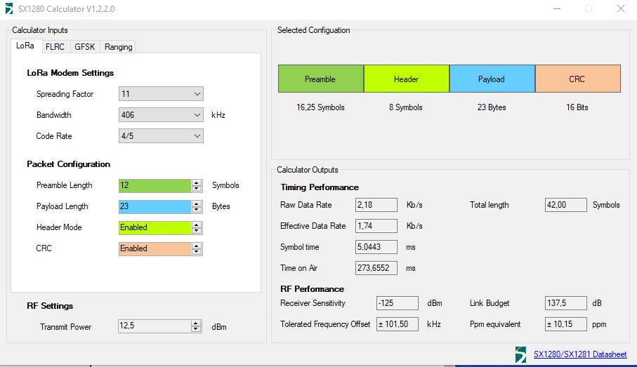
    Furthermore, the default settings used by the library appear to yield a link budget of just 123dB:
    fresh.png
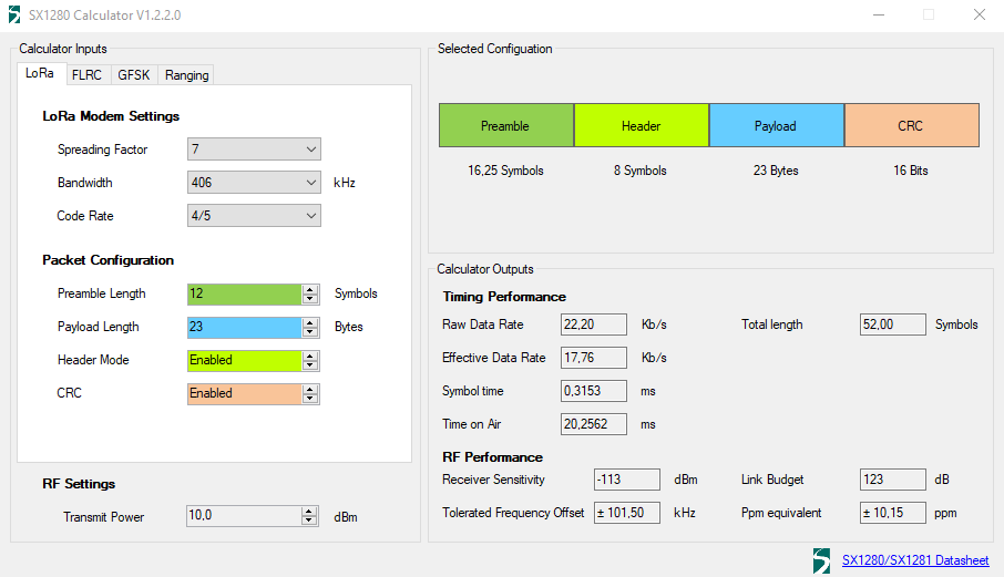
    which is good for a meh transceiver, but not especially awesome for a LoRa transceiver. With such a meh link budget, it's easy to see how a poorly orientated trace antenna could severely impair the packet error rate.

    However, by increasing the spreading factor to 12 and narrowing the bandwidth to 200khz, it's possible to add roughly another 20dB to the link budget:
    juiced.png
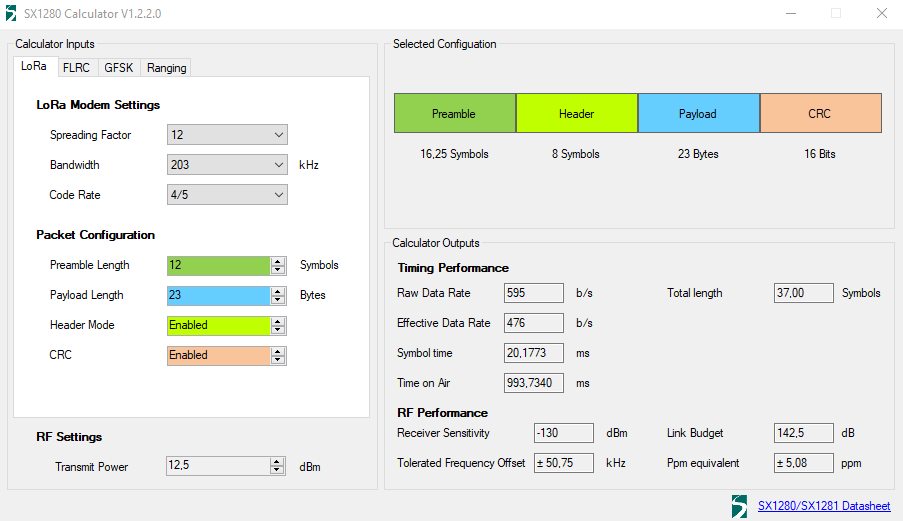
    However, a big downside to this approach is that the transmission time incrases to nearly 1 second, which is a considerable energy drain. Also, the calculator only allows a max transmission power of 12.5dBm, which is well become the module;s advertised maximum transmit power. So,it has me wondering now whether some other register or pin needs to be touched in order to arrive at maximum transmission power. Presumably the SX1280 chip itself has a maximum transmit power of 12.5dBm, and further power would come from activating a power-amplifier on the module, similar to the way the RFM69 module works. However, looking at the manual, this is not the case. Rather, it appears that both the PA and the LNA are permanently activated, and it recommends setting the output power of the SX1280 to 0dBm, at which time the effective output power is 27dBm.

    So, I do that, and increase the spreading factor to 12, and decrease the bandwidth to 203kHz, but the overall performance is still lackluster. That the power output doesn't seem to be obviously easy to adjust is a disappointment. Overall performance falls far below what the 400Mhz AI-Thinker module can achieve, and those modules are very inexpensive (around $1-2 each).

    So.... I'm disappointed. They perform far worse than even the el cheapo NRF24L01 modules that are outfitted with PA + LNA, which operate in the same 2.4Ghz band. This should not be! I'll try them next with some 2.4Ghz pigtail dipole antennas and see whether or not that yields significant improvement, even though it undermines the economics of choosing these modules in the first place. If that also fails, then I'm not sure it's worth the time, money, and effort to troubleshoot it further, especially since Andreas Spiess also wasn't sanguine about his different model 2.4Ghz Ebyte LoRa module either.

    The nice thing about the Ai-Thinker LoRa modules is that they very easily accomodate a wire whip antenna (which are super cheap), whereas these Ebyte modules rely on either the trace antenna (which I now know to be problematic because of its apparent directional sensitivity) or on an IPEX connector, which increases the BOM's antenna price.

    [Edit: I've changed out the power supplies for battery power. No change. I've removed the receiver from the PC, and no change either. Therefore, it either is the antenna, the breadboard wiring, the Ebyte module itself which is at fault, or else interference in the 2.4Ghz band is too much for these LoRa modules to handle (which would be weird, because 2.4Ghz Wi-Fi seems to work well enough, so go figure). I should receive some IPEX antennas this Thursday to try out, and if that doesn't solve it, then I'm going to build something equivalent with RA-01SH 915Mhz LoRa modules by AI-Thinker and see if that breadboard setup is dramatically better or not. Those modules cost around $3 each on Aliexpress ].


  • Mod

    @NeverDie in addition to the energy drain, the module would be transmitting for longer than the 400ms FCC dwell time limit.


  • Hero Member

    @mfalkvidd Good catch! I'll take your word for it. Thank you!

    Reporting back: I found a critical error. The library defaults to leaving the TX_EN and RX_EN pins disconnected. However, this module has a PA and LNA, so it is relevant to it. Since my first attempt merely followed the wiring instructions in the library, I had failed to enable these pins. Now that I have, it's a big improvement.


  • Hero Member

    Thanks to feedback from @mfalkvidd, I've constructed this as the new target:
    faster.JPG

    The directional sensitivity of the trace antenna is still a problem, so it'll have to wait until this Thursday, when the dipole antenna drives, to see whether the latest revision will be good enough or not.


  • Mod

    @NeverDie I am unable to find a better FCC reference than https://lowpowerlab.com/forum/rf-range-antennas-rfm69-library/fcc-rules-for-frequency-hopping/msg16006/?PHPSESSID=6e7efa8daee6de15d09c2b954879be34#msg16006 but that reference says:

    The maximum allowed 20 dB bandwidth of the hopping channel is 500 kHz.

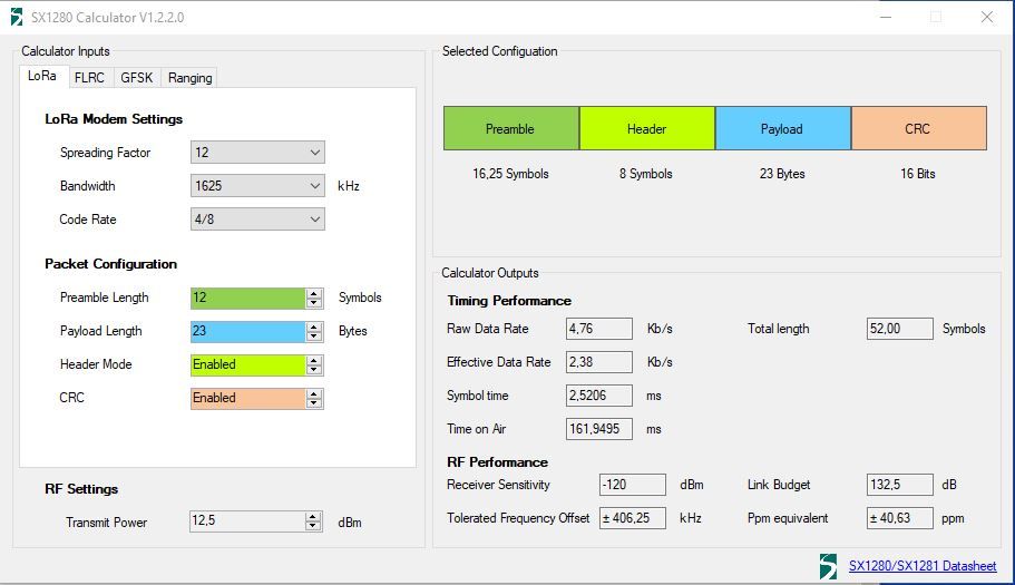
    Since the module is now using 1,625 kHz bandwidth, it is again outside FCC rules.


  • Mod


  • Hero Member

    @mfalkvidd How about this then?

    better.png

    I'm spitballing this. If anyone has a better idea, or a correction, please do post!


  • Mod

    @NeverDie yes, looks good to me


  • Hero Member

    I found an IPEX to SMA adapter, and so I changed the antenna selector to select the soldered on IPEX connector and then borrowed an antenna from an unused wifi base station and connected it to the Ebyte module, like so, just to see if it would work at all.
    antenna_selector.JPG

    Doing this yielded a big improvement in Link Budget. Doing the same type of conversion on the LoRa transmitter module should make a noticeable difference, though I'm doubtful as to whether it will make enough of an improvement that it will perform as well as my AI-Thinker LoRa modules. Nonetheless, I'll attempt another, different, antenna hookup tomorrow when more antenna parts arrive from Amazon, and after testing it, I'll endeavor to reach a final conclusion.

    Chasing down all these loose ends has been tedious, so if anyone finds this blog useful, please leave a thumbs-up to this posting. so that I know I'm not wasting my time writing it all down. At the moment I'm liking my AI-Thinker LoRa modules better: they have much better range and without all this fanfare they seem to "just work" straight out of the box.


  • Hero Member

    It turns out Ebyte is kind enough to recommend specific antennas to use with this LoRa module:
    Ebyte_recommended_antennas_for_2.4Ghz_LoRa.png
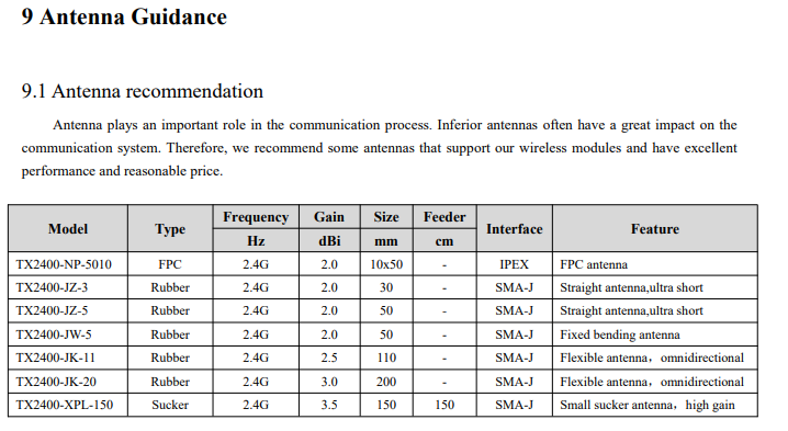
    Unfortunately, these recommended antenna antenna models do not appear to be stocked by either Amazon or Mouser. Instead, it appears you may have to order them fromAliexpress:
    https://www.ebyte.com/en/product-class.html?key=tx2400 So, your best bet would be to order the Ebyte antennas at the same time you order your Ebyte LoRa modules. Unfortunately, I didn't, and I'm now getting the distinct impression that ordering suitable antennas from Amazon is a crapshoot, because I've found supposedly different dipole antennas, but with the exact same dimensions, being marketed for both the 915Mhz band and for the 2.4Ghz band. Surely that can't be right?! 🙄

    https://www.amazon.com/BETAFPV-Omnidirectional-Receiver-Connector-Receiver/dp/B09B21WBYW/ref=sr_1_3?crid=1I052I5H1UXHX&keywords=915mhz%2Bdipole%2Bantenna&qid=1650497087&sprefix=915mhz%2Bdipole%2Bantenna%2Caps%2C124&sr=8-3&th=1


  • Hero Member

    This is, allegedly, one of the TX2400-JW-5 antenna's that Ebyte recommends:
    https://www.aliexpress.com/item/1005003096039403.html?spm=a2g0o.cart.0.0.63133c00YzHVcW&mp=1

    and this, it looks to me, is probably the same antenna, available on amazon:
    https://www.amazon.com/gp/product/B093BVNPBW/ref=ppx_yo_dt_b_asin_title_o04_s00?ie=UTF8&th=1

    and which I'll be testing whenever it finally arrives from amazon (sometime soon). That way I'll be testing within manufacturer guidelines.


  • Hero Member

    Reporting back: I first tried a dipole antenna bought on amazon (link above) that was allegedly for 2.4ghz:
    dipole_antenna.JPG
    I put this on both the transmitter and the receiver. The good news is that the IPEX connector made a very snug fit with the EBYTE module, but the bad news is that the results were terrible:

    5s  Hello World 1234567890*,CRC,DAAB,RSSI,-81dBm,SNR,-2dB,Length,23,Packets,1,Errors,0,IRQreg,8012
    8s  Hello World 1234567890*,CRC,DAAB,RSSI,-87dBm,SNR,-18dB,Length,23,Packets,2,Errors,0,IRQreg,8012
    10s PacketError,RSSI,-78dBm,SNR,-20dB,Length,23,Packets,2,Errors,1,IRQreg,8052,IRQ_RX_DONE,IRQ_HEADER_VALID,IRQ_CRC_ERROR,IRQ_PREAMBLE_DETECTED
    13s PacketError,RSSI,-78dBm,SNR,-14dB,Length,23,Packets,2,Errors,2,IRQreg,8052,IRQ_RX_DONE,IRQ_HEADER_VALID,IRQ_CRC_ERROR,IRQ_PREAMBLE_DETECTED
    15s  Hello World 1234567890*,CRC,DAAB,RSSI,-87dBm,SNR,-16dB,Length,23,Packets,3,Errors,2,IRQreg,8012
    18s PacketError,RSSI,-80dBm,SNR,-7dB,Length,23,Packets,3,Errors,3,IRQreg,8052,IRQ_RX_DONE,IRQ_HEADER_VALID,IRQ_CRC_ERROR,IRQ_PREAMBLE_DETECTED
    32s PacketError,RSSI,-80dBm,SNR,-14dB,Length,23,Packets,3,Errors,4,IRQreg,8052,IRQ_RX_DONE,IRQ_HEADER_VALID,IRQ_CRC_ERROR,IRQ_PREAMBLE_DETECTED
    40s PacketError,RSSI,-85dBm,SNR,-21dB,Length,23,Packets,3,Errors,5,IRQreg,8052,IRQ_RX_DONE,IRQ_HEADER_VALID,IRQ_CRC_ERROR,IRQ_PREAMBLE_DETECTED
    41s PacketError,RSSI,-86dBm,SNR,-17dB,Length,23,Packets,3,Errors,6,IRQreg,8052,IRQ_RX_DONE,IRQ_HEADER_VALID,IRQ_CRC_ERROR,IRQ_PREAMBLE_DETECTED
    101s RXTimeout
    106s PacketError,RSSI,-72dBm,SNR,-12dB,Length,23,Packets,3,Errors,7,IRQreg,8052,IRQ_RX_DONE,IRQ_HEADER_VALID,IRQ_CRC_ERROR,IRQ_PREAMBLE_DETECTED
    114s PacketError,RSSI,-75dBm,SNR,-11dB,Length,23,Packets,3,Errors,8,IRQreg,8052,IRQ_RX_DONE,IRQ_HEADER_VALID,IRQ_CRC_ERROR,IRQ_PREAMBLE_DETECTED
    116s PacketError,RSSI,-76dBm,SNR,-11dB,Length,23,Packets,3,Errors,9,IRQreg,8052,IRQ_RX_DONE,IRQ_HEADER_VALID,IRQ_CRC_ERROR,IRQ_PREAMBLE_DETECTED
    

    So, time to finally try the factory recommended antenna (also linked above). Unfortunately, the IPEX to SMA adapter I got was the wrong kind (female SMA instead of male SMA), so I had to fall back onto the only one Ipex-to-male-sma adapter I had. So, I put that on the receiver and left the transmitter with the dubious dipole antenna:
    factory_recommended.JPG
    More bad news was that the IPEX connector on this adapter made a rather loosey-goosey connection to the Ebyte module. How can that be? Are there different sizes/types of IPEX connectors or something? But, I went with it anyway because it's all I have at the moment, and the good news is that the result was tangible improvement:

    4s  Hello World 1234567890*,CRC,DAAB,RSSI,-67dBm,SNR,-3dB,Length,23,Packets,1,Errors,0,IRQreg,8012
    6s PacketError,RSSI,-67dBm,SNR,-2dB,Length,23,Packets,1,Errors,1,IRQreg,8052,IRQ_RX_DONE,IRQ_HEADER_VALID,IRQ_CRC_ERROR,IRQ_PREAMBLE_DETECTED
    7s  Hello World 1234567890*,CRC,DAAB,RSSI,-72dBm,SNR,-11dB,Length,23,Packets,2,Errors,1,IRQreg,8012
    9s  Hello World 1234567890*,CRC,DAAB,RSSI,-66dBm,SNR,-3dB,Length,23,Packets,3,Errors,1,IRQreg,8012
    10s  Hello World 1234567890*,CRC,DAAB,RSSI,-67dBm,SNR,-2dB,Length,23,Packets,4,Errors,1,IRQreg,8012
    11s  Hello World 1234567890*,CRC,DAAB,RSSI,-71dBm,SNR,-7dB,Length,23,Packets,5,Errors,1,IRQreg,8012
    13s  Hello World 1234567890*,CRC,DAAB,RSSI,-66dBm,SNR,2dB,Length,23,Packets,6,Errors,1,IRQreg,8012
    15s PacketError,RSSI,-68dBm,SNR,-6dB,Length,23,Packets,6,Errors,2,IRQreg,8052,IRQ_RX_DONE,IRQ_HEADER_VALID,IRQ_CRC_ERROR,IRQ_PREAMBLE_DETECTED
    18s  Hello World 1234567890*,CRC,DAAB,RSSI,-66dBm,SNR,-5dB,Length,23,Packets,7,Errors,2,IRQreg,8012
    19s PacketError,RSSI,-71dBm,SNR,-14dB,Length,23,Packets,7,Errors,3,IRQreg,8052,IRQ_RX_DONE,IRQ_HEADER_VALID,IRQ_CRC_ERROR,IRQ_PREAMBLE_DETECTED
    20s  Hello World 1234567890*,CRC,DAAB,RSSI,-64dBm,SNR,0dB,Length,23,Packets,8,Errors,3,IRQreg,8012
    23s  Hello World 1234567890*,CRC,DAAB,RSSI,-65dBm,SNR,0dB,Length,23,Packets,9,Errors,3,IRQreg,8012
    25s  Hello World 1234567890*,CRC,DAAB,RSSI,-66dBm,SNR,1dB,Length,23,Packets,10,Errors,3,IRQreg,8012
    28s  Hello World 1234567890*,CRC,DAAB,RSSI,-65dBm,SNR,-3dB,Length,23,Packets,11,Errors,3,IRQreg,8012
    29s  Hello World 1234567890*,CRC,DAAB,RSSI,-73dBm,SNR,-10dB,Length,23,Packets,12,Errors,3,IRQreg,8012
    30s  Hello World 1234567890*,CRC,DAAB,RSSI,-71dBm,SNR,-10dB,Length,23,Packets,13,Errors,3,IRQreg,8012
    32s PacketError,RSSI,-66dBm,SNR,-15dB,Length,23,Packets,13,Errors,4,IRQreg,8052,IRQ_RX_DONE,IRQ_HEADER_VALID,IRQ_CRC_ERROR,IRQ_PREAMBLE_DETECTED
    33s  Hello World 1234567890*,CRC,DAAB,RSSI,-71dBm,SNR,-9dB,Length,23,Packets,14,Errors,4,IRQreg,8012
    34s  Hello World 1234567890*,CRC,DAAB,RSSI,-75dBm,SNR,-12dB,Length,23,Packets,15,Errors,4,IRQreg,8012
    36s  Hello World 1234567890*,CRC,DAAB,RSSI,-74dBm,SNR,-10dB,Length,23,Packets,16,Errors,4,IRQreg,8012
    37s  Hello World 1234567890*,CRC,DAAB,RSSI,-67dBm,SNR,-1dB,Length,23,Packets,17,Errors,4,IRQreg,8012
    38s PacketError,RSSI,-72dBm,SNR,-20dB,Length,23,Packets,17,Errors,5,IRQreg,8052,IRQ_RX_DONE,IRQ_HEADER_VALID,IRQ_CRC_ERROR,IRQ_PREAMBLE_DETECTED
    39s PacketError,RSSI,-68dBm,SNR,-5dB,Length,23,Packets,17,Errors,6,IRQreg,8052,IRQ_RX_DONE,IRQ_HEADER_VALID,IRQ_CRC_ERROR,IRQ_PREAMBLE_DETECTED
    42s  Hello World 1234567890*,CRC,DAAB,RSSI,-71dBm,SNR,-7dB,Length,23,Packets,18,Errors,6,IRQreg,8012
    

    What's immediately evident is a big improvement in both the RSSI and the SNR. Bear in mind that this improvement is with the factory recommended antenna on only the receiver module. The seemingly lousy dipole antenna is still on the transmitter module.

    So.... next step is to order the right kind of IPEX to male SMA connector and see how it fares when the factory recommended antenna is connected to both the transmitter module and the receiver modules.


  • Hero Member

    A related topic is: just what kind of component is the antenna selector anyway?
    antenna_selector.png
    My measurements suggest it is just a zero ohm resistor. It's very tiny, however, which makes it difficult to desolder and then re-solder to the right pads when changing the selection. I did do that on the receiver module, but on the transmitter module I removed the selector component and then used a solder bridge to enable the IPEX antenna connector and disable the trace antenna.


  • Hero Member

    Reporting back: Answering my own question about the retention force on u.fl connectors, it turns out you may get only 5 connects/disconnects before the connector is shot and needs replacing. Source:
    How to Achieve Maximum U.fl RF Connector Reliability – 07:09
    — airborne0x0

    So, I'm guessing that why the u.fl connector on only my u.fl to sma adapter cable became loosey-goosey, as I described above. Fortunately, at least according to this source, the u.fl connector on the PCB doesn't wear out. It's just the cable connector side that does.


  • Mod

    Yes, the antenna selector is normally just a zero ohm resistor.

    About the antenna sma connector: there are 4 connectors, not 2.
    1f36edb6-0bb4-420b-b60a-f6ac252178e2-image.png


  • Hero Member

    @mfalkvidd Thanks for that! So, it appears that what I need are the RP-SMA connectors, not the SMA connectors. All the wifi stuff is generally RP-SMA for instance. Yet another picture (duplicative of yours) to drive it home:
    alt text
    I had thought that maybe the threading was also different, but what I now gather that's not the case, as it wasn't needed to render the two standards incompatible. It's helpful to know that the RP-SMA standard was created for wifi, specifically so that wifi users wouldn't plug their wifi stuff into non-wifi stuff. Well, you potentially can, because the threading is the same, but you'll either get no joy from it or might even damage your connectors, because the inner connector will be the wrong gender. IMHO, they really should have changed the threading too as a further precaution and named it "reverse gender" instead of "reverse polarity", since polarity seemingly has nothing to do with it. i.e. the outer casing is ground in both standards, and the inner conductor is what carries the signal in both standards. But, they didn't, and now we have to live with it.

    Fun fact: what I was calling the number of "connect/disconnects" is technically referred to as the number of "mating cycles".


  • Mod

    @NeverDie note that the picture you found has different naming for the RP variant than the picture I found.

    RP-SMA male vs RP-SMA plug female socket
    RP-SMA female vs RP-SMA jack male pin

    Confusion deluxe.


  • Hero Member

    @mfalkvidd Good catch! I hadn't even noticed until you pointed it out. If even the people who make pictures meant to clarify are confused.....


  • Mod

    @NeverDie the rule I learned (which is not politically correct, but memorable) is that the male always does the screwing and if the male doesn't have a d**k it's reverse polarity.

    The key here is to not focus on the signal connector, but on the mating. The female versions are fixed, the male versions screw on to the female.


  • Hero Member

    @mfalkvidd After checking just now what's for sale on amazon, your picture seems to be the right one. However, that phrase you have is bringing me to the wrong conclusion (the picture I posted). I mean, consider the RP-SMA female connector picture (referring to the picture you posted). You would think that would be male if anything is if that phrase was right. I mean, it screws "into" something else, and it has a d**k. Yet, evidently, its proper designation is female. Go figure.


  • Mod

    @NeverDie no. It doesn’t screw into anything. It is fixed. It cannot be turned without turning the entire cable. Hence the male is the one doing the screwing. The male variant can turn without turning the cable.


  • Hero Member

    @mfalkvidd Thanks! It finally makes sense now that you've explained it like that.


  • Hero Member

    Which thickness of coax cable should one prefer? Is thicker generally better? For instance, here are two connector cables of the same type, and both 50 ohm, but one is 0.81mm coax, and the other is 1.13mm coax. Does the difference matter?

    https://www.amazon.com/gp/product/B098QGFZ2J/ref=crt_ewc_title_dp_3?ie=UTF8&psc=1&smid=AODZVW3FCSGNT

    https://www.amazon.com/gp/product/B098QF5XF8/ref=crt_ewc_title_dp_1?ie=UTF8&psc=1&smid=AODZVW3FCSGNT

    [Edit: I do notice that they have different IPEX connectors, but I'm wondering just about the coax diameter.]


  • Hero Member

    I'll see it through to the end, but I think at this point Ebyte 2.4Ghz LoRa is now academic. With all this antenna nonsense getting in the way of a simple, inexpensive solution, it just doesn't hold a candle to a fully integrated solution, like this simple, compact LoRa gateway, where even a simple spring antenna is sufficient:
    LoRa_gateway.JPG

    The shield on top can be demounted and is a fully-standalone atmega328p driving the LoRa radio, which makes for a complete solution that's not much larger than the AI-Thinker module itself! I'll just drop a 915Mhz Ai-Thinker LoRa module into place instead of the 433Mhz module currently there, and, bang, it should "just work."

    I suppose desoldering the IPEX connector on the EBYTE module I could perhaps make a short jumper run from a custom PCB onto the EBYTE antenna pad..... Hmmm.... Kludgy, but it might work. In contrast, however, with the AI-Thinker modules there's a through-hole already set aside for a whip antenna.


  • @NeverDie The characteristic impedance of the coax is what matters. And that is all determined by the construction, which includes the thickness, but also other things, like what dielectric, and probably even what metal is used. (I don't know all the variables that they have to play with.)

    So it could be that both of those options you posted are fine. But buying stuff like this on Amazon, especially through third parties is a crap shoot. No telling if it will be good or not, and the reviews aren't usually very helpful, either, on RF stuff. Not saying you shouldn't do it - I will gamble myself, but just go in fully aware that your chances of getting something shoddy are good, and make sure the price you pay is worth the gamble.


  • Hero Member

    @ejlane Agreed. Where is it that you prefer to shop?

    A lot of the amazon stuff is the same as what one might find on Aliexpress, but the difference is I can get it fast and with free shipping from Amazon, and returns are a breeze. When it comes to quality, I think Mouser or Digikey usually has the best, but at usually higher prices even before you figure in shipping. Is there anywhere else worth considering? Maybe there's a good resource I've overlooked.


  • @NeverDie I think you've pretty much covered it. Yes, sometimes there's no good hobby-level alternative to Amazon/Aliexpress if you want it cheap.

    Though someplace like SparkFun or Adafruit can be good for hobbyists, though you'll pay for it.

    Along with Mouser and Digikey, sometimes I have good luck with Arrow or Newark. But really, it's nice to do a search with octopart.com or findchips.com if you have a pretty good idea of what you want. They will look at lots of vendors, even some that might be shading towards gray market. Can really save some time, and sometimes find things that I never would have otherwise. Saved me a few months ago on a customer project that would have otherwise had to be completely redesigned.


  • Hero Member

    Reporting back: Today I received proper IPEX to RP-SMA connector cable. I hooked up both the transmitter and receiver using them to the factory recommended 2.4ghz antennas. The transmitter and receiver are two rooms apart, and the signal has to pass through two closed doors. What I'm getting doesn't look great:

    4s PacketError,RSSI,-74dBm,SNR,-4dB,Length,23,Packets,0,Errors,1,IRQreg,8052,IRQ_RX_DONE,IRQ_HEADER_VALID,IRQ_CRC_ERROR,IRQ_PREAMBLE_DETECTED
    7s PacketError,RSSI,-79dBm,SNR,-15dB,Length,23,Packets,0,Errors,2,IRQreg,8052,IRQ_RX_DONE,IRQ_HEADER_VALID,IRQ_CRC_ERROR,IRQ_PREAMBLE_DETECTED
    9s PacketError,RSSI,-77dBm,SNR,-11dB,Length,23,Packets,0,Errors,3,IRQreg,8052,IRQ_RX_DONE,IRQ_HEADER_VALID,IRQ_CRC_ERROR,IRQ_PREAMBLE_DETECTED
    12s PacketError,RSSI,-73dBm,SNR,-1dB,Length,23,Packets,0,Errors,4,IRQreg,8052,IRQ_RX_DONE,IRQ_HEADER_VALID,IRQ_CRC_ERROR,IRQ_PREAMBLE_DETECTED
    13s  Hello World 1234567890*,CRC,DAAB,RSSI,-78dBm,SNR,-6dB,Length,23,Packets,1,Errors,4,IRQreg,8012
    14s PacketError,RSSI,-79dBm,SNR,-8dB,Length,23,Packets,1,Errors,5,IRQreg,8052,IRQ_RX_DONE,IRQ_HEADER_VALID,IRQ_CRC_ERROR,IRQ_PREAMBLE_DETECTED
    16s PacketError,RSSI,-78dBm,SNR,-4dB,Length,23,Packets,1,Errors,6,IRQreg,8052,IRQ_RX_DONE,IRQ_HEADER_VALID,IRQ_CRC_ERROR,IRQ_PREAMBLE_DETECTED
    18s PacketError,RSSI,-82dBm,SNR,-17dB,Length,23,Packets,1,Errors,7,IRQreg,8052,IRQ_RX_DONE,IRQ_HEADER_VALID,IRQ_CRC_ERROR,IRQ_PREAMBLE_DETECTED
    26s PacketError,RSSI,-80dBm,SNR,-22dB,Length,23,Packets,1,Errors,8,IRQreg,8020,IRQ_HEADER_ERROR,IRQ_PREAMBLE_DETECTED
    28s PacketError,RSSI,-79dBm,SNR,-9dB,Length,23,Packets,1,Errors,9,IRQreg,8052,IRQ_RX_DONE,IRQ_HEADER_VALID,IRQ_CRC_ERROR,IRQ_PREAMBLE_DETECTED
    31s PacketError,RSSI,-85dBm,SNR,-19dB,Length,23,Packets,1,Errors,10,IRQreg,8052,IRQ_RX_DONE,IRQ_HEADER_VALID,IRQ_CRC_ERROR,IRQ_PREAMBLE_DETECTED
    32s PacketError,RSSI,-83dBm,SNR,-7dB,Length,23,Packets,1,Errors,11,IRQreg,8052,IRQ_RX_DONE,IRQ_HEADER_VALID,IRQ_CRC_ERROR,IRQ_PREAMBLE_DETECTED
    35s  Hello World 1234567890*,CRC,DAAB,RSSI,-77dBm,SNR,-8dB,Length,23,Packets,2,Errors,11,IRQreg,8012
    37s PacketError,RSSI,-82dBm,SNR,-15dB,Length,23,Packets,2,Errors,12,IRQreg,8052,IRQ_RX_DONE,IRQ_HEADER_VALID,IRQ_CRC_ERROR,IRQ_PREAMBLE_DETECTED
    50s  Hello World 1234567890*,CRC,DAAB,RSSI,-81dBm,SNR,-17dB,Length,23,Packets,3,Errors,12,IRQreg,8012
    51s  Hello World 1234567890*,CRC,DAAB,RSSI,-81dBm,SNR,-12dB,Length,23,Packets,4,Errors,12,IRQreg,8012
    54s PacketError,RSSI,-79dBm,SNR,-4dB,Length,23,Packets,4,Errors,13,IRQreg,8052,IRQ_RX_DONE,IRQ_HEADER_VALID,IRQ_CRC_ERROR,IRQ_PREAMBLE_DETECTED
    57s  Hello World 1234567890*,CRC,DAAB,RSSI,-74dBm,SNR,-6dB,Length,23,Packets,5,Errors,13,IRQreg,8012
    60s PacketError,RSSI,-78dBm,SNR,-14dB,Length,23,Packets,5,Errors,14,IRQreg,8052,IRQ_RX_DONE,IRQ_HEADER_VALID,IRQ_CRC_ERROR,IRQ_PREAMBLE_DETECTED
    62s  Hello World 1234567890*,CRC,DAAB,RSSI,-75dBm,SNR,-6dB,Length,23,Packets,6,Errors,14,IRQreg,8012
    67s PacketError,RSSI,-84dBm,SNR,-20dB,Length,23,Packets,6,Errors,15,IRQreg,8052,IRQ_RX_DONE,IRQ_HEADER_VALID,IRQ_CRC_ERROR,IRQ_PREAMBLE_DETECTED
    69s PacketError,RSSI,-78dBm,SNR,-12dB,Length,23,Packets,6,Errors,16,IRQreg,8052,IRQ_RX_DONE,IRQ_HEADER_VALID,IRQ_CRC_ERROR,IRQ_PREAMBLE_DETECTED
    72s  Hello World 1234567890*,CRC,DAAB,RSSI,-77dBm,SNR,-11dB,Length,23,Packets,7,Errors,16,IRQreg,8012
    76s PacketError,RSSI,-79dBm,SNR,-13dB,Length,23,Packets,7,Errors,17,IRQreg,8052,IRQ_RX_DONE,IRQ_HEADER_VALID,IRQ_CRC_ERROR,IRQ_PREAMBLE_DETECTED
    78s  Hello World 1234567890*,CRC,DAAB,RSSI,-79dBm,SNR,-12dB,Length,23,Packets,8,Errors,17,IRQreg,8012
    80s  Hello World 1234567890*,CRC,DAAB,RSSI,-76dBm,SNR,-7dB,Length,23,Packets,9,Errors,17,IRQreg,8012
    83s PacketError,RSSI,-75dBm,SNR,-7dB,Length,23,Packets,9,Errors,18,IRQreg,8052,IRQ_RX_DONE,IRQ_HEADER_VALID,IRQ_CRC_ERROR,IRQ_PREAMBLE_DETECTED
    86s PacketError,RSSI,-78dBm,SNR,-6dB,Length,23,Packets,9,Errors,19,IRQreg,8052,IRQ_RX_DONE,IRQ_HEADER_VALID,IRQ_CRC_ERROR,IRQ_PREAMBLE_DETECTED
    103s PacketError,RSSI,-76dBm,SNR,-18dB,Length,23,Packets,9,Errors,20,IRQreg,8052,IRQ_RX_DONE,IRQ_HEADER_VALID,IRQ_CRC_ERROR,IRQ_PREAMBLE_DETECTED
    105s PacketError,RSSI,-81dBm,SNR,-18dB,Length,23,Packets,9,Errors,21,IRQreg,8052,IRQ_RX_DONE,IRQ_HEADER_VALID,IRQ_CRC_ERROR,IRQ_PREAMBLE_DETECTED
    108s PacketError,RSSI,-79dBm,SNR,-3dB,Length,23,Packets,9,Errors,22,IRQreg,8052,IRQ_RX_DONE,IRQ_HEADER_VALID,IRQ_CRC_ERROR,IRQ_PREAMBLE_DETECTED
    109s  Hello World 1234567890*,CRC,DAAB,RSSI,-78dBm,SNR,-3dB,Length,23,Packets,10,Errors,22,IRQreg,8012
    110s  Hello World 1234567890*,CRC,DAAB,RSSI,-79dBm,SNR,-6dB,Length,23,Packets,11,Errors,22,IRQreg,8012
    112s PacketError,RSSI,-78dBm,SNR,-3dB,Length,23,Packets,11,Errors,23,IRQreg,8052,IRQ_RX_DONE,IRQ_HEADER_VALID,IRQ_CRC_ERROR,IRQ_PREAMBLE_DETECTED
    

    I think maybe the breadboard construction and long wires are introducing too much unwanted signals, resulting in lowered performance. The only way I can think of to get rid of that would be to make a specialty PCB that puts an atmega328p in close proximity with the module, so that there aren't long wires or long traces to pick up noise along the way.

    Or, maybe it's something else. In any case, I'm going to pause this and switch-over to a 915Mhz AI-Thinker module to see whether I get more traction there.


  • Hero Member

    Re-thinking this, probably the easiest way to exclude whether or not the breadboarding and related wiring is a crippling source of noise would be to create a PCB that an Arduino Pro Mini can dock with and which makes all the needed connections directly to the E28-2G4M27S. It's so easy that I should have thought of it in the first place! I have started work on it, and I'll post a rendering when its ready. I may post it in openhardware.io, and I think I may take a similar approach to future breakout boards as well. Pro-mini's are so cheap that it will make for a good way to test different radio modules.


  • Hero Member

    What happened to prices? I checked just now and pro mini's are selling for $5+. Pre-pandemic they could be had for closer to $1.


  • @NeverDie Haven't you heard of the chip shortage? It's changed everything, and prices for those things that are even available have generally gone up. (Though somehow magically, the ESP32 seems to be pretty much untouched. You can still buy them, and prices have been relatively stable. I don't know how they've done it.) AVR, PIC, STM chips have all been hard to get specific models, and at times any model that has the features. I expect other brands were similar, but those are the ones that I've looked for.

    I hope they someday go back, but for the foreseeable future, expect it to be like this.

    Pro minis for close to $1 was always a shock, since even at 1k qty, just the chip itself costs more than that. So to get to that price for the whole assembled board, there must be some kind of gray-market thing going on. If I were to try to make a profit on 1k at a time, assembled and everything, I'm pretty sure the final price would have to be in the ballpark of $10 each.


  • @ejlane & @NeverDie: Amazing technology that was available for $1 was … too hard to believe. Even $5 for a ProMini is pretty mind-blowing. Not that I buy commodities, I do buy these components a dozen at a time to save on shipping even when it is ‘free’. I laugh at myself when I spend a week of my time on a $2 chip and then wonder how I can rework it from a PCB (never worth the attempt). Compared to any other hobby or habit this radio-electronic stuff is cheaper than cooking top-ramen at home.
    BTW, thanks for the radio discussion posted last week. I will read and learn later.


  • Hero Member

    Here's the schematic for what I have in mind:
    Drop_In.png

    Thinking about it more, I don't think it makes sense to post it to openhardware.io until I've proven that it provides a big improvement over the breadboard, because if it turns out that it isn't an improvement, it might be drawing attention away from more worthy projects.

    Anyhow, I'll most likely use a similar method for building a test setup for the 915Mhz Thinker-AI radio, as it's ultimately more robust and less clumsy than breadboarding. In the meantime though I'll be breadboarding some old school 915Mhz LoRa modules to see whether going down that path is likely to bear fruit or not.


  • Hero Member

    So as to have a point of comparison, I today hooked up some old school SX1276 915Mhz LoRa modules (based on an Adafruit breakout board: https://www.adafruit.com/product/3072?gclid=EAIaIQobChMIxJm5r6-w9wIV_WxvBB0GjwCCEAQYASABEgLRofD_BwE ), and the difference is like night and day in performance:
    adafruit915MhzLora.JPG
    At the same distance as with previous tests, it works 100% flawlessly:

    377s  Hello World 1234567890*,CRC,DAAB,RSSI,-74dBm,SNR,10dB,Length,23,Packets,108,Errors,0,IRQreg,50
    378s  Hello World 1234567890*,CRC,DAAB,RSSI,-74dBm,SNR,9dB,Length,23,Packets,109,Errors,0,IRQreg,50
    379s  Hello World 1234567890*,CRC,DAAB,RSSI,-74dBm,SNR,10dB,Length,23,Packets,110,Errors,0,IRQreg,50
    381s  Hello World 1234567890*,CRC,DAAB,RSSI,-74dBm,SNR,10dB,Length,23,Packets,111,Errors,0,IRQreg,50
    382s  Hello World 1234567890*,CRC,DAAB,RSSI,-74dBm,SNR,10dB,Length,23,Packets,112,Errors,0,IRQreg,50
    383s  Hello World 1234567890*,CRC,DAAB,RSSI,-74dBm,SNR,9dB,Length,23,Packets,113,Errors,0,IRQreg,50
    384s  Hello World 1234567890*,CRC,DAAB,RSSI,-74dBm,SNR,9dB,Length,23,Packets,114,Errors,0,IRQreg,50
    385s  Hello World 1234567890*,CRC,DAAB,RSSI,-74dBm,SNR,9dB,Length,23,Packets,115,Errors,0,IRQreg,50
    386s  Hello World 1234567890*,CRC,DAAB,RSSI,-74dBm,SNR,9dB,Length,23,Packets,116,Errors,0,IRQreg,50
    387s  Hello World 1234567890*,CRC,DAAB,RSSI,-74dBm,SNR,9dB,Length,23,Packets,117,Errors,0,IRQreg,50
    388s  Hello World 1234567890*,CRC,DAAB,RSSI,-74dBm,SNR,9dB,Length,23,Packets,118,Errors,0,IRQreg,50
    389s  Hello World 1234567890*,CRC,DAAB,RSSI,-74dBm,SNR,9dB,Length,23,Packets,119,Errors,0,IRQreg,50
    390s  Hello World 1234567890*,CRC,DAAB,RSSI,-74dBm,SNR,9dB,Length,23,Packets,120,Errors,0,IRQreg,50
    391s  Hello World 1234567890*,CRC,DAAB,RSSI,-74dBm,SNR,9dB,Length,23,Packets,121,Errors,0,IRQreg,50
    392s  Hello World 1234567890*,CRC,DAAB,RSSI,-74dBm,SNR,9dB,Length,23,Packets,122,Errors,0,IRQreg,50
    394s  Hello World 1234567890*,CRC,DAAB,RSSI,-74dBm,SNR,10dB,Length,23,Packets,123,Errors,0,IRQreg,50
    395s  Hello World 1234567890*,CRC,DAAB,RSSI,-74dBm,SNR,9dB,Length,23,Packets,124,Errors,0,IRQreg,50
    396s  Hello World 1234567890*,CRC,DAAB,RSSI,-74dBm,SNR,9dB,Length,23,Packets,125,Errors,0,IRQreg,50
    397s  Hello World 1234567890*,CRC,DAAB,RSSI,-75dBm,SNR,10dB,Length,23,Packets,126,Errors,0,IRQreg,50
    398s  Hello World 1234567890*,CRC,DAAB,RSSI,-71dBm,SNR,10dB,Length,23,Packets,127,Errors,0,IRQreg,50
    399s  Hello World 1234567890*,CRC,DAAB,RSSI,-74dBm,SNR,10dB,Length,23,Packets,128,Errors,0,IRQreg,50
    400s  Hello World 1234567890*,CRC,DAAB,RSSI,-73dBm,SNR,9dB,Length,23,Packets,129,Errors,0,IRQreg,50
    401s  Hello World 1234567890*,CRC,DAAB,RSSI,-75dBm,SNR,9dB,Length,23,Packets,130,Errors,0,IRQreg,50
    402s  Hello World 1234567890*,CRC,DAAB,RSSI,-74dBm,SNR,10dB,Length,23,Packets,131,Errors,0,IRQreg,50


    which, quite frankly, is what I had been expecting from the 2.4GHz modules. Notice that these are also on breadboards, yet the SNR is vastly superior to what the Ebyte modules were reporting. So, although I can't yet say so definitively, I'm starting to suspect that there's something wrong with the Ebyte 2.4Ghz LoRa modules that I received. If I had a couple 2.4Ghz LoRa modules from a different manufacturer, it might tell the tale. As it stands, it doesn't much matter the reason, since performance at 915Mhz is so much better.

    I'll next try running the Ebyte modules direct from two AA batteries. If there's noise in the present power supplies, that should remove it. I've already put decoupling caps on the radio module, but I could also do the same with the Arduino Pro Mini. Sooner or later we'll find the culprit. If worse comes to worst, I'll fabricate this low noise test board and try it with that:
    low_noise_test_board.png


  • Hero Member

    Semtech did write a paper analyzing possible interference between the SX1280 LoRa and WiFi. Here is the conclusion:

    LoraWifiImmunity.png

    Not exactly sure what it means. Looks as though it doesn't have as much immunity to 802.11n as to 802.11g, which is maybe(?) a problem given how common 802.11n is these days. Reducing bandwidth and increasing spreading factor are the recommended workarounds. Unfortunately, all my neighbors have wi-fi, so finding unused spectrum, or with low enough signal, may not be feasible at 2.4Ghz.

    Come to think of it, I do have a dual-band meshed wi-fi network at home. I hadn't thought I needed tri-band, but this might be a case where backhauling over that third band, or possibly ethernet, might knock down some of the wi-fi generated "noise" in the 2.4Ghz spectrum. If this turns out to be part of the issue, then, indeed, going to 915Mhz instead would be a lot easier solution.


  • Hero Member

    One more reason for preferring 915Mhz over 2.4Ghz: The SX1262 (915Mhz) has a receive sensitivity of -148dBm, whereas the SX1280 (2.4Ghz) is only -132dBm. I hadn't realized the gap was so large. All by itself that's an appreciable difference. I suspect that to cash-in on all the potential receive sensitivity, it may require a TCXO, but I'd have to look that up to be sure. Now granted, external PA's and LNA's might be employed, but as far as the chips themselves, the max transmit power on the SX1280 is 12.5dBm, whereas on the SX1262, it's 22dBm, so at the chip level the SX1262 is more capable on the transmit side by a considerable degree.

    Comparing the SX1262 to the SX1276 (Adafruit that I tested today), the receive sensitivities are the same. The SX1276 has a max Tx power of 20dBm, so the SX1262's 22dBm transmit power is only just a little better. The SX1262 may be more energy efficient, but in terms of raw link budget, it's almost the same as the SX1276. So, for some applications, such as gateways, using SX1276 chips/modules might make sense if they're cheaper. However, looking at current market pricing, they don't appear to be. Strange.


  • Hero Member

    Reporting back: I tried running both transceivers off of two AA's with decoupling capacitors and... no change. I also tried varying the location, in case there was a strong local interference source. No change. Again, to recap: RSSI seems good, but SNR seems bad. So, the next thing left to try is the low noise PCB I pictured above. I'll do that, but fabrication will have to wait until I have other PCB's ready to be fabbed as well so as to save on shipping by combining the orders, because at this point getting these Ebyte SX1280 modules to work satisfactorily is looking more and more like a long shot. 😞 Given that Andreas Spiess was also not particularly sanguine about his Ebyte SX1280 LoRa modules, I suspect the blame may lay with the modules. Anyhow, it's becoming academic, because I'm moving on to 915Mhz LoRa, since from what I've seen firsthand so far that seems much more robust, and on paper an SX1262 or SX1276 handily outperforms an SX1280.


  • @NeverDie Hi, I've just started playing with a pair of these modules that I've had kicking around for a while. Fascinating thread and I haven't finished reading through yet, thanks for being so thorough!

    I'm using the same library. When it comes to enabling the TX_EN and RX_EN pins, can you clarify how? Is it done through the microcontroller script, or by setting the pin inputs to high (+3.3v)?


  • Hero Member

    @samh For the receiver node, I simply wired RX_EN to 3.3V and TX_EN to GND. For the transmitter module, I found that wiring TX_EN direcctly to 3.3V doesn't work so well (probably too high a duty cycle for the PA to be operating continuously like that), so I instead wired TX_EN to a spare pin and I modified the code so as to drive that pin HIGH just prior to transmitting and drive it to LOW when done transmitting. Also, on the transmitter node I wired RX_EN to ground. This seemed to work. However, it reminds me now that this was really just improvisation on my part for expediency in getting something setup fast.. Perhaps I should be using pull-up and/or pull-down resistors instead. Thanks for bringing up this topic! I'll investigate further. Please do post what you end up using youself, as well as whether you are getting similar or different results regarding noise (SNR) and/or range.


  • Hero Member

    Reporting back: It turns out that in the settings.h file, you can assign pins for TX_EN and RX_EN. I assigned Arduino pin 4 for TX_EN and pin 5 for RX_EN, and it works fine.

    I also inserted 10K resistors as a "just in case". I also increased TX_POWER to 10.

    I'm not sure which of the 3 changes made the most difference, but the result is noticeable improvement. SNR is still reported as low., but I am now getting reliable longer range than previously. Maybe SNR is just not measured accurately by the module?

    IIRC, the module has two forms of integrated step-down within the chip: an LDO and a buck converter. Not sure which one the library defaults to (I'll have to look it up) but if it's the buck, then switching over to the LDO might help with the SNR.

    [Edit: I just now checked, and the library defaults to using the LDO rather than the buck converter]


  • Hero Member

    Last update: I changed frequencies to 2.42Ghz, and SNR became a bit better, so maybe interference in the 2.4Ghz band really does play a role. It still performs much worse than the 915Mhz LoRa nodes I i discussed above however. At this point the next noticeable improvement, if anything, probably won't happen until I fab the custom low noise PCB which I showed above.


  • Thanks for letting me know, I'm going to play around with these over the weekend and I'll try to report back. Not too bothered about getting optimal performance since it's my first time messing with RF specifically in an arduino project, just want to do some basic testing. Some 868 modules are for sure on my list to check out next


  • Hero Member

    @samh Great! Looking forward to hearing how it goes for you. It's very helpful to compare notes.


  • Hero Member

    Regarding the 915Mhz SX1262, the Dorji brand seems interesting. They sell two different module types: one, the DRF1262T, with a TCXO at 1ppm, and one, the DRF1262G, with a non-TCXO crystal (uses less power) which they say is 10ppm. They also have a breakout board for Arduino Uno to facilitate testing:
    https://www.ebay.com/itm/192665058568
    https://www.ebay.com/itm/202574135410
    https://www.ebay.com/itm/202436579399

    So, in addition to the AI-Thinker Ra-01SH modules, I've ordered some of these DRF1262T/G to compare performance. Hopefully at least one of the three different models will be a winner.


  • @NeverDie, Thanks again for all the blogging on this subject. If you have not yet ordered your custom low-noise PCB, I had one design idea. If you flip the ProMini orientation end over end most of the traces will be shorter, especially the RX/TX lines. I’ve not examined the code, but I’d think that the RX/TX connections have the most signal activity on the board, thus EMI potential. I like how you keep all the traces on one side. That should solve the interrupted ground-plane problem we learned from Rick Hartley above.

    It is far more fun to roll-your-own. Alternatively, I was thinking … I just checked the Moteino breakout boards from Felix at LowerPowerLabs to see if those would work with your Ebyte radios: too bad, different pinout. I just bought a few Moteinos (915 mhz) boards to save myself from my low-quality solder jobs and shaky hands – only $13 but I have to add my own radio or spend another $7. Everything I've seen from LowPowerLabs has been high quality.


  • I've finally made a little progress over the last two days. Lots of background reading on the excellent SX12XX library and some tinkering to make a portable radio modem for future testing

    Here's the transmit end soldered up to a little bit of prototyping board I had lying around, which it turned out was the perfect size to fit the E28+breakout, Arduino Pro Mini, and voltage reg! All powered off a tiny 2S LiPo at the moment. The antennas are external Happymodel ELRS-intended and are supposedly 5dB...

    20220429_185809.jpg

    20220502_204110.jpg

    The voltage divider is included for battery monitoring. I modified the 'varying power' library examples (numbers 10/20) to include sending one battery voltage packet per test and print serial bytes in a slightly more interpretable format for a python script to read and save to csv.

    Just as a proof of concept, I looked at how RSSI/SNR vary with Tx power and RF attenuation, see below:

    • TC1 = line of sight, 3-4m separation
    • TC2 = as TC1 but cross-polarised antennas
    • TC3 = several brick walls of attenuation
    • TC4 = as TC3 but cross-polarised antennas
      (and yes, the axes are intentionally the wrong way around since it's easier to fit the plots on a horizontal screen this way!)

    untitled_2.png

    Clearly something is working right as RSSI drops off linearly with Tx power! SNR performance leaves a bit to be desired but seems that @NeverDie had similar results. Not very exciting but showing the setup is correct for now and I can move on to some more interesting things.

    Next up is to have a look at implementing the PA/LNA on the E28 modules and seeing what kind of difference I get in performance. Spotted the RX/TX_EN pins in the library documentation so I'll give those a go


  • Hero Member

    @samh Great stuff! I look forward to hearing more. As you probably know, the buck/boost converter (whichever it is) that's in your photo is a possible source of noise. I can't say whether, in reality, it would be or not. That's one of the reasons why (below), I'm planning to run directly from batteries only.

    @Larson Good suggestions. I decided to dump the pro mini idea and just make my own barebones pro mini, because pro mini's come with three things that aren't useful and actually get in the way: 1. the LDO, 2. the oscillator, and 3. the LED on pin 13. I'm hoping (but haven't confirmed) that by eliminating the oscillator on pins D20 and D21, I can use those pins to drive two LED's kinda "for free" since nobody uses those pins for anything. So, the first draft looked like this:
    Ra-01_pro_mini.png
    to get the shortest possible lines, like you said. It also includes a TPL5010 as an ultra low current wakeup timer. The main thing, though, is that it runs from two AA batteries, which are directly attached to the PCB itself. Well, this design was working out fine, but it seemed a bit tedious to redo it for each possible radio I wanted to test, so I think I'm settling on this instead as a test platform:
    new_draft.png
    which amounts to a stripped down pro mini (plus two I2C pinsout at the bottom for plugging in a TH sensor, or whatnot). In this case, the idea is to do a simple breakout board for each radio and connect it as a shield to the unused pins on the atmega328p. I figure it should be easier than doing a complete, fully integrated board for each radio. And I like that it's of minimal size (the footprint of two AA batteries), yet packs enough power that I expect it should have no trouble supplying even 200ma if needed just from the batteries themselves.

    I'm lucky in that I have a Dragon programmer, so I can both burn the bootloader and set the fuses on the atmega328p prior to soldering it into place on the PCB. From past experience, the sleep current on the atmega328p itself can be as low as 100na. In the past when Pro Mini's sold for only a buck, I leaned toward using Pro Mini's for everything. These days I guess I'll roll my own.

    I think eventually I want to replace the canonical 6 pin FTDI connection with a 5 pin picoblade. I've only just started looking into that. I was favoring the idea of using 1.0mm pitch JST-SH conectors for the task, but sourcing them didn't look easy. So, I'm reluctantly settling on the 1.25mm pitch picoblade instead. If there exists something even more compact (maybe some kind of 2x3 row of pins on a connector), then I'd be keen to hear what it is.

    The AA battery connectors are the Keystone 92, which look like this:
    Kyestone92.jpeg

    In the end, it might look like an improved variation of one of these:
    https://www.openhardware.io/view/395/LoRa-Ra-01-ATmega328P-Node
    https://www.openhardware.io/view/268/Arduino-Pro-Mini-Shield-for-RFM69HW
    https://www.openhardware.io/view/480/Compact-nRF24L01-Pro-Mini-Bottom-Shield
    but this time a bit more of a general purpose razor and blades system, if you catch my meaning. This time it will be a little wider than a pro mini, so it will be possible to fit any radio onto the shield. That said, I always liked the simplicity and ease of assembly of the "LoRa Ra-01 ATmega328P node". Perhaps the biggest improvement is the tight integration of the batteries, which in most designs are left "flapping in the breeze" as an afterthought for the builder to sort out.

    Anyhow, I have a bit more work to do, but that's the current evolution. As always, any thoughts, reactions, suggestions, or feedback appreciated.


  • @NeverDie. You are way out there, man! Thanks to the references to the other boards made by you. What fantastic contributions to the maker market.
    I suppose D20 and D21 are the same as PCINT6/XLTAL1 and PCINT7/XTAL2? I once reassigned RX and TX on an Attiny85 to RX and TX (edit: output functions) as I was pin limited. It took some doing, but that is the beauty of these multifunction pin assignments. The code, if I remember, had to be in the loop after a delay in the setup; that gave me a way to access the RX/TX pins again to reprogram if necessary. Maybe there are similar challenges with bypassing the crystal.
    @samh. So you are setting power levels on the fly. Very clever.


  • Hero Member

    @samh My first reaction is that your SNR is better than mine, especially for the measurements of going through several brick walls--though it's a bit hard to read the TC1-4 symbols when they're printed over one another, so I'm not completely sure. Since you also have some longish wires, I wouldn't be at all surprised if the cheap breadboards I used are, in one manner or another, impairing my SNR. This is where comparing notes can really be helpful. Thanks!

    Despite China's lockdown, it looks as though my Ra-01SH modules may be here before long, so I want to get my test PCB orders in soon!

    Looking forward to finally having a single test bed for comparing the performance of different radios modules! i.e. the only thing to change from one test to another will be the radio (and possibly software). For instance, it will be nice to know that when the bits "absolutely, positively, have to get there", which radio can do it reliably but also with the least amount of total energy? I mean, LoRa has the promise of great range, but the transmission time can be so long that may come at a pretty high energy price.... unless maybe the link budget allows the Tx power to be hugely reduced. That's what I'd very much like to know. i.e. which is ultimately better, if the figure of merit is energy spent per successfully delivered bit? FSK or LoRa? Or something else? Probably somebody out there in industry or the military or in academia has studied this question using the best equipment (or at least simulations) and published about it, but nothing beats real empirical results from whatever gear you have in your actual hands--because at the end of the day that's all you have to work with anyway. The cool thing is that the Semtech chips can do both FSK and LoRa, so you have the option to choose whatever best fits the situation, or switch back and forth depending on changing conditions. Ask near as I can tell, the FSK component of the Semtech LoRa radio chips is, essentially, an improved form of the RFM69's radio (which is also made by Semtech). My guess is that if you can get your packets delivered at 2mbps using an NRF24L01 (or equivalent NRF5x), then that's going to be the most energy efficient delivery method. But, if that doesn't work reliably enough, what's your next best option to get your bits delivered, and your next best option after that, etc.? And it's not just that: you need to compare sleep current consumption and wake-up times as well. Fun fact: when in the past I ran the numbers for mostly sleeping sensor devices, most often it's the sleep current consumption that dominates.


  • Hero Member

    @ejlane said in Anyone using/tried the E28-2G4M27S 2.4Ghz LoRa SX1280 27dB module?:

    @NeverDie Haven't you heard of the chip shortage? It's changed everything, and prices for those things that are even available have generally gone up. (Though somehow magically, the ESP32 seems to be pretty much untouched. You can still buy them, and prices have been relatively stable. I don't know how they've done it.) AVR, PIC, STM chips have all been hard to get specific models, and at times any model that has the features. I expect other brands were similar, but those are the ones that I've looked for.

    I hope they someday go back, but for the foreseeable future, expect it to be like this.

    Pro minis for close to $1 was always a shock, since even at 1k qty, just the chip itself costs more than that. So to get to that price for the whole assembled board, there must be some kind of gray-market thing going on. If I were to try to make a profit on 1k at a time, assembled and everything, I'm pretty sure the final price would have to be in the ballpark of $10 each.

    When is this chip shortage supposed to end? I thought the prices for atmega328pb's on mouser were reasonable enough, but then I just now noticed they weren't expected to be in stock until March 2023! LOL. Matter of fact, Mouser doesn't have any atmega328p's of any kind in stock at all. Unfortunately, as near as I can tell, the new attiny3226's, which are in stock, don't appear to be picopower, so the sleep currents aren't as good. Matter of fact, I can't deduce from its datasheet just what the poweroff current consumption of it is.


  • @NeverDie As far as when the shortage ends, ??? I've seen estimates different times that it's "right around the corner" but nothing that was very convincing to me. Intel just this week or last came out and said that they think it's going to be better soon. NVidia chips/cards are getting to be more available. And random different chips have re-appeared, so maybe they're right this time? I wouldn't bet on it, though. There are still tons of parts that are hard or impossible to get in any quantity. I'm no insider, though. I shop at Digikey, Mouser, etc. same as you. Just maybe more often and a bit higher qty sometimes.

    I actually have some of the Attiny3226 here to play with. When they came into stock, I bought a small bag of them. I haven't yet had a chance to do anything with them, though. I do see power consumption tables. pg 477-478 of the datasheet. https://www.mouser.com/datasheet/2/268/ATtiny3224_3226_3227_Data_Sheet_DS40002345B-2887812.pdf Numbers seem pretty reasonable, for a claimed 'low power' family of chips.


  • Hero Member

    @ejlane Aha! Bingo! Thanks for the page reference! Looks as though attiny3226 is the same 100na in powerdown as the atmega328p:
    attiny3226_powderdown_consumption.png
    Giving it a quick look, it seems both better and cheaper. What's not to like about this thing? I guess maybe just the total dearth of tutorials regarding it?


  • @NeverDie Yeah, I think they are the next gen device. I believe that this batch that came out in the past ~6 months was the first production run of the '2' series devices. At least it was the first time that I had seen them available, though it wasn't something I had been actively searching for.

    Should be about an identical AVR instruction set, but some of the low level stuff like registers might have changed, so it might take a bit of work to convert projects to it. I haven't done it yet to know.


  • Hero Member

    Something to consider regarding the modules is that the maximum rated instantaneous current draw, according to the datasheet is 580ma:
    maxCurrent.png
    That's worthy of note because the maximum current rated for a usb 2.0 port is just 500ma. So, if you're powering it from a USB 2.0 port off your computer via an LDO, that's potential problem #1. A USB 3.0 port, on the other hand, is rated for 900ma, so that would be fine. However, if you're powering it from most FTDI connectors (which typically max out at 50ma when operating at 3.3v mode), that's still going to be a problem. In this case, powering it from a Sparkfun Beefy 3 may be a solution, as "Built upon the same foundation as our 3.3V SparkFun FTDI Basic Breakout, the Beefy 3 is equipped with an AP2112K voltage regulator making this FTDI basic breakout board capable of handling a current load of up to 600 mA!" However, that's still cutting it very close though to the 580ma that the datasheet says is required. If you're powering it by some other means, you'll want to be sure you aren't backdriving your FTDI connection, as that wouldn't be good either.

    My solution? I'm going to create my own custom 3.3v FTDI to UART board that can handle higher current (probably 1 amp or more) just to be sure I have enough headroom for a standalone solution. While I'm at it, I'll make sure to pick a low noise LDO....

    [Edit: I think I'll go with the LT1965 LDO: https://www.mouser.com/datasheet/2/609/1965fb-1269903.pdf for it's overkill capability. Rated at 1.1a current, low noise, and big enough that it should be able to disappate heat better than some of the smaller, lower cost alternatives. That will also make it useful as a more general purpose tool. ]


  • @NeverDie But that's only the instantaneous current needed for transmitting data over the radio. The receive current is more like what it will be doing the majority of the time. Put a beefy capacitor or two on the power line and they should handle those short little spikes.

    I mean, you're not going to have a super-complicated web page on there or something. The packets being sent out will be what 1kB or something max, even serving a simple web page? According to this page: https://docs.espressif.com/projects/esp-idf/en/latest/esp32/api-guides/wifi.html#esp32-wi-fi-throughput you might get close to 80MBit/s speed. With some overhead, maybe the packet needs 10kBit, so it would only need to be on for 125uS. Even if the packets were far larger, the amount of time the radio needs to transmit is still a small fraction of the overall time. So just choose your capacitor(s) accordingly, and you'll be fine.


  • @NeverDie Oh, whoops, looks like you're probably talking about a different module? I saw the transmit number, and had been recently talking about the ESP32, which has a similar TX power number, and looks like I misread your post.

    The overall point remains, but it depends on the TX time vs. the rest of the time for the overall average power consumption and the size of capacitor needed.


  • Hero Member

    @ejlane Yes, good point about using a capacitor to compensate.
    27dB Tx power is, not considering inefficiencies, nominally equal to roughly 0.5amp, so the stated 580ma is probably about right and not mostly just in-rush current. LoRa transmissions can be rather lengthy, but I suppose a sufficiently large capacitor could compensate for that as well.

    As it turns out I already went ahead and did a draft layout in KiCad for it:
    High_amperage_3.3v_FTDI.png
    Having already invested the time, I'm going to build it. The low noise aspect LT1965 LDO might (?) still make a difference. I also like that it has a USB-B connector on it for a nice solid connection that's mechanically anchored to the PCB (none of that surface mount micro usb rubbish). I've wanted one for quite a while, and now its moment has finally come. If anyone else has interest, I can post it to openhardware.io


  • Hero Member

    Anyhow, back to the project at hand. I completed design of two different barebones mcu boards (one is just atmega328p and the other allows an Arduino pro mini to dock with it instead) that are 2xAA battery powered:
    basic_mcu_boards_horz.JPG
    Given the wait time from a PCB fab, I went with two different designs just in case I made an error and one of them doesn't work. They both have identical test points where I can separately monitor current consumed by the mcu vs current consumed by the radio--all the better to tease apart what's really going on. Then I also have five different radio shields that fit either mcu board exactly the same:
    5_different_radio_shields.JPG

    As JLPCB doesn't work on weekends, I'm going to design a few more boards and then submit them all on Sunday night. When they finally do arrive in the mail, I'll not only be better able to evaluate the E28-2G4M27S (because the new design should practically eliminate any hardware noise), but also compare the following radios against one another for their relative performance on the exact same platform: 2.4Ghz E28-2G4M27S, three different kinds of 915Mhz SX1262 LoRa, a number of different kinds of 2.4GHz nRF24L01 (all with PA and LNA to put them on the same playing field as the other radios in the round-up), a 915Mhz RFM69HW, and a 400Mhz Ra-01 LoRa. Of interest to me are what makes for a reliable "worst case" range in my home environment at different transmission power levels and if anything stands out as a clear winner in terms of energy efficiency for bits that are reliably delivered. By worst case, I mean transmitting from behind a cement footer almost 6 feet beneath grade to a second story room across the house diagonally at the point furthest from it. If transmissions can work reliably along that transmission path, then they're probably good between any other two points in the house as well. There is, for instance, no way that a bog standard nRF24L01 could deliver any packets along that path, because its transmit power is just 0dB. However, with appropriate "boosting" via PA and LNA, I think it has a chance. In comparison, I previously tested the 400Mhz LoRa along this path, and it worked without a hitch. Matter of fact it could reach a quarter mile (or better) in all directions outside the house as well using just the default parameters in the old RadioHead libraries. I'll try that test again, but this time with the new library to see if it fares any differently this time around, as well as try LoRa at 915Mhz and 2.4Ghz.

    Depending on how the testing goes, I may leverage the same platform to also try out some other inexpensive radio modules that I've seen on Aliexpress that, up to now, I've lacked an easy way to comparison test. For instance, some featuring radio chips made by Texas Instruments (CC1101, CC1310, CC1352, CC1120, CC2450, CC2640, CC2650, and a whole slew of others) and some featuring radio chips made by Silicon Labs (e.g. Si4463). If you know of chips that you're keen to try, let me know and maybe I can try them for you in a way that will be meaningful because of the comparisons. I'm not expecting that big differences will emerge that aren't already known, but testing will cut through the marketing propaganda and (hopefully) reveal the truth.


  • @NeverDie I've never done a LoRa project, but I remember reading somewhere that some packets can take multiple seconds! So yeah, that would take a very large capacitor. I'm not sure what I would do in that scenario. I'd have to give it some thought, but I also might go with a dedicated power supply that could just handle the full current. Of course it would also depend on the specific trade-offs that were best for that project. Interesting problem.

    Are you sure about JLCPCB not working on weekends? I 95% sure that I've submitted designs on Saturdays before and gotten a reply that they were accepted later that same day. I've also once or twice gotten things rejected when I made a silly mistake that they caught. I'm sure that it's a person reviewing things, and they have caught a couple errors. (Not in logic, obviously, but I had done a quick change one time, and a trace on another part of the board also got moved somehow, and it crossed over another. That's the only one I remember what the problem was.)

    However, you can also always add boards to an order that is in process and they'll ship together for one price. Though if you're adding enough boards then there will be a bit of a shipping differential to pay for.

    Those sound like some fun tests, and I look forward to hearing the results!


  • Hero Member

    @ejlane said in Anyone using/tried the E28-2G4M27S 2.4Ghz LoRa SX1280 27dB module?:

    Are you sure about JLCPCB not working on weekends? I 95% sure that I've submitted designs on Saturdays before and gotten a reply that they were accepted later that same day.

    On Thursday I asked "Eric", their sales rep, and he said they don't work or do production on weekends. He said that if I send the files Sunday night, it would most likely ship on Wednesday. And he said the same would be true if I sent them on Friday. All this assumes no errors in the gerber/drill files.

    I'm impressed with JLBPCB in that they take the size of the board into consideration when quoting larger quantities. So, for instance, on one tiny board, I'll be getting 30 for just $4.40, even though getting 5 would cost me the $4 minimum. For some reason, though, if the order is larger than 30 boards of the same design, then it triggers a new minimum fee of around $9 or $10, IIRC. Not really sure why that is. It's a pity, because if I wanted a hundred or something for cheap, I'd have to panelize onto one PCB (Eric said no v-grooving or mouse bites allowed without paying a price penalty) and then saw/cut the boards apart after they're delivered. Fortunately, for most things, quantity 30 is a big enough number.


  • @NeverDie Okay, sounds like you know more than I do about it, I guess. I was sure that I had gotten responses/work done on a weekend, but maybe my memory is just faulty.

    But yes, their service is very impressive. And for a 2 layer board, I can get it delivered here on the west coast USA in usually 6 calendar days from ordering with the quickest shipping. That's shockingly quick, and faster than most local places can even just make the board. (Well faster than any that I know of. I've pretty much switched to only using JLCPCB. Hardly even bother quoting other places these days.)

    I believe if you really needed a bunch, they would be a decent price even with the penalties. Every time I've had to pay an extra charge for something, it was a reasonable amount. Though I've never tried to order 100 of anything through them, so I could be wrong.


  • Hero Member

    @ejlane said in Anyone using/tried the E28-2G4M27S 2.4Ghz LoRa SX1280 27dB module?:

    @NeverDie Okay, sounds like you know more than I do about it, I guess. I was sure that I had gotten responses/work done on a weekend, but maybe my memory is just faulty.

    But yes, their service is very impressive. And for a 2 layer board, I can get it delivered here on the west coast USA in usually 6 calendar days from ordering with the quickest shipping. That's shockingly quick, and faster than most local places can even just make the board. (Well faster than any that I know of. I've pretty much switched to only using JLCPCB. Hardly even bother quoting other places these days.)

    In pre-pandemic times, I could order on a Monday from allpcb.com and get my order delivered by Friday here in the US. These days... not sure if that's true anymore, as I haven't ordered from them since before the pandemic.

    I believe if you really needed a bunch, they would be a decent price even with the penalties. Every time I've had to pay an extra charge for something, it was a reasonable amount. Though I've never tried to order 100 of anything through them, so I could be wrong.

    Eric basically said "Please don't panelize" and that it wouldn't save money. Now I think I understand why: if you do a lousy job of either the vgrooving or mouse bites, it's going to interfere with their manufacturing process. e.g. maybe that part of their much larger project board shatters to bits during fabrication because it's too weak structurally. It's much better for them (at least from their cost of business) to be in complete control of it. Otherwise, some engineer might have to remediate somebody's poor panelization, which takes extra time and throws a wrench into their work flow.


  • Hero Member

    @ejlane said in Anyone using/tried the E28-2G4M27S 2.4Ghz LoRa SX1280 27dB module?:

    I've also once or twice gotten things rejected when I made a silly mistake that they caught. I'm sure that it's a person reviewing things, and they have caught a couple errors. (Not in logic, obviously, but I had done a quick change one time, and a trace on another part of the board also got moved somehow, and it crossed over another. That's the only one I remember what the problem was.)

    I took JLCPCB's capabilities and, to the degree possible, imported them into KiCAD's design rule constraints:
    jlcpcb_constraints.png

    This has surfaced violations that didn't get flagged by KiCAD's default design rule constraints--problems that I'm guessing JLCPCB would have kicked back at me if this method hadn't found them first.


  • @NeverDie this video is very useful


  • Hero Member


  • @NeverDie I've only done my own panelization maybe 2 or 3 times ever. Usually just leave it to the board house, but 10 or so years ago, before the board houses were quite this cheap and I was on more of a budget because of saving for a down payment, I did try it out for some personal projects as an experiment.

    But I didn't even try to do v-grooves. Not sure if whichever one I was using would even allow it. I just left extra room between the active parts of the board on the PCB and literally took tin snips and cut them apart with that. With 1 cm between boards it's easy to not hit anything.

    Obviously doing it like that wouldn't weaken their board, but if you need precise board shape/size then this wouldn't do it. Ever since then the prices have gotten so low that I don't bother trying. I would be interested knowing what about JLCPCB's process makes them want to limit any order to the 30 pieces. That's always seemed a bit weird to me. I would think they would welcome the extra volume/money.

    But weirdly enough, I don't even know where to go for larger orders. I mean, I can do a search like anyone else, but I don't have direct experience. By the time it gets to that qty, then the assembly house deals directly with whoever they work with to get the boards made. At that point it's not me dealing with them directly, except for passing requirements to the client, who then passes them to the assembly house, etc.

    I've also entered some of their limitations into KiCad, but I'm not sure if I did a complete job of it. I try to be a bit more conservative than being right at the manufacturable edge. But yeah, get the rules to catch as much as possible. I think my problems came in when I did something that such a minor change I didn't even really think about running the rules again, and of course something like that is usually harmless, but every once in a while it does something unexpected, so obviously the rules need to be checked after every change, and every time before exporting gerbers for manufacturing. And I try to do that, but still these days I'm sure that are times that I forget.


  • @NeverDie said in Anyone using/tried the E28-2G4M27S 2.4Ghz LoRa SX1280 27dB module?:

    If you know of chips that you're keen to try, let me know

    Since you asked, maybe look at the good-old cheap 433 MHz transmitter/receivers? Maybe you are sticking to transceivers so this wouldn’t fly. Or maybe you are staying away from ASK modulations. I’m sure these cheapo radios won’t pass your fundaments concrete/cross-house test, but it would be another data point. This season I’ve been slowly reworking my limited 433 MHz home network of motion detectors. Having failed to transmit through concrete/cross-house pathways, I built some 433 repeaters that successfully worked on a line-of-site pathways that allowed me to look around the corners. I have found these TX radios & SR501 motion detectors just sip energy and my 4-pack of AA batteries last for, in some cases, over 3 years.

    As you are working with JLCPCB are you using them for assembly? I did so last year with different project and had really good results. I did have some difficulty finding compatible components, so I suspect that they won’t be able to resource all your radios… but that was some time ago and I have much to learn. I look forward to doing more assembly with JLCPCB. It was also really inexpensive and a great way to get around my poor home soldering quality.

    [edit: forgot to say, @NeverDie and everyone else: What a great thread. Thanks for building and sharing. I have learned much here.]


Log in to reply
 

Suggested Topics

  • 4
  • 3
  • 14
  • 274
  • 2
  • 933

23
Online

11.2k
Users

11.1k
Topics

112.5k
Posts