Most reliable "best" radio
-
@Larson said in Most reliable "best" radio:
I wondered if the PCB antenna could be cut with a dremel tool and be fitted with an equivalent whip-wire. It would be cheap enough to try. It looks to be that the NRF24's are maybe making that easier? Again, cheap enough to try.
No need to guess. It's been done already. Here's one of the mods:
Cheap DIY NRF24L01 Antenna Modification – 02:48
— Pete BThis one looks even better: https://www.instructables.com/Enhanced-NRF24L01/
I haven't tried either one, but I do believe them when they say it helps improve range a lot.
@NeverDie said in Most reliable "best" radio:
No need to guess. It's been done already. Here's one of the mods:
Very interesting. Based on the measurements the author, Pete B, shows, the on-board antenna length is 33.3% the 1/4 Lambda WL. He adds 66.7% for a total 1/4 Lambda. I'll say the same thing is probably true for the ESP8266 antennae lengths. I'm looking forward to trying this with the ESP.
[Edit: My mistake. I looked at this further. The full 2.4GH WL is 4.92". So, the onboard measured 1.64" WL is a 1/3 WL. The additional 3.28" would bring the total WL to 1.0 * WL. Several simple RSSI tests would show the results. Frist test would be no change for a base case. Then test with the addition. Then one could cut the wire back to 3/4 WL, 1/2 WL, 1/4 WL, then finally remove the antenna to verify the original test, or to inspect for circuit damage.]
-
@Larson said in Most reliable "best" radio:
You have been hard at work.
Yup, and although it's jumping the gun, I think I'm ready to reach conclusions. For battery powered nodes, I think for short-range the answer is si24R1, because it offers 2mbps and 7dBm and you can buy tiny, compact modules with in-built PCB antennas for around 50 cents each, as you have already done. Also, mysensors offers over-the-air updates with nRF24L01/si24R1, which is compelling. So, if you have a gateway within range, I see no problem with those radios. For longer range, I think the answer is SX1262 because FCC allegedly allows higher transmit power with spread spectrum, and it has a very large potential link budget. If powered by mains, I'd say ESP8266, which is what I will use to gateway the si24R1 and SX1262 motes. I could test and compare more radios, but I don't have infinite time, so I think that's as far as I'm going to take it for now. If anyone else wants to try more stuff and report back and/or make comparisons, I'd say by all means go for it. For instance, anything that does genuine frequency hopping would be worth looking into. Frequency Hopping would maybe get the best of both worlds, with a combination of high speed, a large link budget, and interference avoidance. This guy does a comparison of LoRa vs Frequency Hopping, and you can see why Frequency Hopping Spread Spectrum seems more compelling than LoRa:
LoRa Vs Spread Spectrum FHSS 2.4 GHz – 10:13
— 0033merWhat's interesting is that the FHSS module he demos actually uses the nRF24L01 chip inside it to accomplish the FHSS! See https://www.ebyte.com/en/new-view-info.html?id=450 So, I take that to mean that with the right software, one could program an MCU to get the nRF24L01 to do FHSS. I do wonder though just how it manages to do it. AFAIK, true FHSS requires psuedo-random changes in frequency while transmitting a single packet, not sending short packets in a pseudo-random sequence of different frequencies. Hmmm.... Maybe it just strips off all the header bytes, and does it that way? Maybe then there would be no difference. I'm guessing maybe that's how they do it. You could compute your own CRC and send the CRC bytes as part of the payload instead of in a separate part of the frame. In fact, that might even be better, because then you could do CRC32, whereas the nRF24L01 hardware encoding seems limited to CRC16. You send what would have been frame bytes as purely payload bytes, creating a kind of virtual Frame. Also, by chopping up the transmission--you could effectively send payloads that are longer than 32 bytes, which is the limit for any single packet on the nRF24L01--by loading and sending more than one pipe's worth of data. This is notionally similar to how I was able to get the nRF24L01 to transmit continuously (see earlier post) without dropping into standby/idle between packets.
@NeverDie said in Most reliable "best" radio:
conclusions
Yes, I feared that I would be too late to the game to help. I hope to report back with some results after the boat from China arrives. I'd like to do the 2-D map of RSSI values with different radios.
-
@Larson said in Most reliable "best" radio:
unzip the resulting *.zip file.
Uh, oh. As Bug's Bunnny would say, you may have made a wrong turn at Albuquerque, or, in this case, on step 3.
There is, I think, a much simpler way. Instead of manually unzipping the .zip file and trying to make sense of the contents, do this instead: in Kicad 6, under the "File..." menu, go to "Unarchive project...." and give it the intact .zip file. It will instantly recreate the entire project on the spot, exactly where I left off with it. It really couldn't be simpler. Try it. You'll like it.
Regardless, thanks for the feedback. I just now changed the instructions on the openhardware.io projects to make it more clear what to do.
@NeverDie said in Most reliable "best" radio:
Try it. You'll like it.
I tried about 5 times. I'm able to get to the project files but not through KiCAD (6.0.05) using File/UnarchiveProject so ultimately, I've succeeded. File/UnarchiveProject takes the *.zip file just fine, but it does not deliver the *.pcb, *.prl, *.pro, and *.sch files. File/UnarchiveProject does deliver the *.rar file along with the "design" and "image" directories. File/UnarchiveProject won't take a *.rar file. So ultimately, I use the zip utility to get it. The important part is that I can see the files in KiCAD.
Reporting from the slow road, Larson.
-
@NeverDie said in Most reliable "best" radio:
conclusions
Yes, I feared that I would be too late to the game to help. I hope to report back with some results after the boat from China arrives. I'd like to do the 2-D map of RSSI values with different radios.
@Larson said in Most reliable "best" radio:
@NeverDie said in Most reliable "best" radio:
conclusions
Yes, I feared that I would be too late to the game to help. I hope to report back with some results after the boat from China arrives. I'd like to do the 2-D map of RSSI values with different radios.
Sounds good. The game isn't going anywhere. It'll still be here whenever you're ready. It never ends, and it will outlive both of us.
-
@Larson said in Most reliable "best" radio:
I wondered if the PCB antenna could be cut with a dremel tool and be fitted with an equivalent whip-wire. It would be cheap enough to try. It looks to be that the NRF24's are maybe making that easier? Again, cheap enough to try.
No need to guess. It's been done already. Here's one of the mods:
Cheap DIY NRF24L01 Antenna Modification – 02:48
— Pete BThis one looks even better: https://www.instructables.com/Enhanced-NRF24L01/
I haven't tried either one, but I do believe them when they say it helps improve range a lot.
@NeverDie That 'antenna modification' just looks crazy to me, but I have not tried it. However the designers will have spent some time on getting the pcb stripline antenna to be matched to the transmitters impedance. Adding a random bit of wire on the end will screw this up royally.. You never see this on TV antennas or anywhere else for that matter (maybe some nutter with a car aerial made from a coat hanger).
Also I would expect that the design is to be as wide band as possible but centered on the mid frequency in the range available. So the further you move away from 'centre' frequency (Ch63) then the worse the antenna is likely to perform. But at the power levels used here the effects might be marginal. I have always found moving the RF board a cm or two can make a big difference in link quality.
Here is the link to the E32 arduino library..... https://www.arduino.cc/reference/en/libraries/ebyte-lora-e32-library/
-
@NeverDie That 'antenna modification' just looks crazy to me, but I have not tried it. However the designers will have spent some time on getting the pcb stripline antenna to be matched to the transmitters impedance. Adding a random bit of wire on the end will screw this up royally.. You never see this on TV antennas or anywhere else for that matter (maybe some nutter with a car aerial made from a coat hanger).
Also I would expect that the design is to be as wide band as possible but centered on the mid frequency in the range available. So the further you move away from 'centre' frequency (Ch63) then the worse the antenna is likely to perform. But at the power levels used here the effects might be marginal. I have always found moving the RF board a cm or two can make a big difference in link quality.
Here is the link to the E32 arduino library..... https://www.arduino.cc/reference/en/libraries/ebyte-lora-e32-library/
Regarding the antenna extensions, you raise some good points. The people who posted them seem like they thought it genuinely helped, but maybe I was gullible and was wrong to post the links. If so, I'm sorry. On the other hand, it might take only 5 minutes to try them out and see whether or not they work. A simple trial experiment would maybe settle it one way or the other pretty quickly.
@skywatch said in Most reliable "best" radio:
Here is the link to the E32 arduino library..... https://www.arduino.cc/reference/en/libraries/ebyte-lora-e32-library/
Thanks. What was it you were wanting me to notice about the e32 library? If it was about the FHSS, that was an e34 module in the youtube video.
-
Regarding the antenna extensions, you raise some good points. The people who posted them seem like they thought it genuinely helped, but maybe I was gullible and was wrong to post the links. If so, I'm sorry. On the other hand, it might take only 5 minutes to try them out and see whether or not they work. A simple trial experiment would maybe settle it one way or the other pretty quickly.
@skywatch said in Most reliable "best" radio:
Here is the link to the E32 arduino library..... https://www.arduino.cc/reference/en/libraries/ebyte-lora-e32-library/
Thanks. What was it you were wanting me to notice about the e32 library? If it was about the FHSS, that was an e34 module in the youtube video.
@NeverDie said in Most reliable "best" radio:
Regarding the antenna extensions, you raise some good points. The people who posted them seem like they thought it genuinely helped, but maybe I was gullible and was wrong to post the links. If so, I'm sorry.
We are all here to share and learn and help each other out - I was only adding my thoughts on the matter for all to consider.
On the other hand, it might take only 5 minutes to try them out and see whether or not they work. A simple trial experiment would maybe settle it one way or the other pretty quickly.
Yes it would, but positioning needs to be carefully maintained to avoid false results.
@skywatch said in Most reliable "best" radio:
Thanks. What was it you were wanting me to notice about the e32 library? If it was about the FHSS, that was an e34 module in the youtube video.Oh darn it! - I got it mixed up - I am sorry for posting the wrong lib!
-
@NeverDie said in Most reliable "best" radio:
Regarding the antenna extensions, you raise some good points. The people who posted them seem like they thought it genuinely helped, but maybe I was gullible and was wrong to post the links. If so, I'm sorry.
We are all here to share and learn and help each other out - I was only adding my thoughts on the matter for all to consider.
On the other hand, it might take only 5 minutes to try them out and see whether or not they work. A simple trial experiment would maybe settle it one way or the other pretty quickly.
Yes it would, but positioning needs to be carefully maintained to avoid false results.
@skywatch said in Most reliable "best" radio:
Thanks. What was it you were wanting me to notice about the e32 library? If it was about the FHSS, that was an e34 module in the youtube video.Oh darn it! - I got it mixed up - I am sorry for posting the wrong lib!
@skywatch said in Most reliable "best" radio:
Yes it would, but positioning needs to be carefully maintained to avoid false results.
I think for a gateway it could make sense to use two nRF24L01 modules spaced a half wavelength apart. Then for reception you'd get all the benefits of antenna diversity, and for transmission to a particular node you could simply pick the module that receives the most packets out of the two from that node, which should give the better signal path. That could cut down on the sensitivity to positioning by better avoiding null zones.
-
@NeverDie That 'antenna modification' just looks crazy to me, but I have not tried it. However the designers will have spent some time on getting the pcb stripline antenna to be matched to the transmitters impedance. Adding a random bit of wire on the end will screw this up royally.. You never see this on TV antennas or anywhere else for that matter (maybe some nutter with a car aerial made from a coat hanger).
Also I would expect that the design is to be as wide band as possible but centered on the mid frequency in the range available. So the further you move away from 'centre' frequency (Ch63) then the worse the antenna is likely to perform. But at the power levels used here the effects might be marginal. I have always found moving the RF board a cm or two can make a big difference in link quality.
Here is the link to the E32 arduino library..... https://www.arduino.cc/reference/en/libraries/ebyte-lora-e32-library/
@skywatch said in Most reliable "best" radio:
That 'antenna modification' just looks crazy to me,
And that is why it will be fun to test. I corrected my post above and made comments on testing.
[Edit: It was my bad for drawing people down this dark alley of antenna modifications. I’ve learned much from dark allies and only been beaten-up a few times. Yet, I still go there… to learn. Therefore, I will test it and reply.]
-
I just now did a current measurement, and, unfortunately, the allegedly smd NRF24L01's on amazon do not appear to be either nRF24L01's nor si24R1's, because the max Tx current is not a match for either:
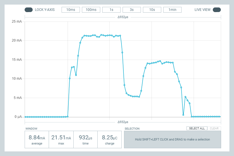
The Tx current is too high to be an nRF24L01, and it's too low to be an si24R1. I'll have to look at some of the alternative datasheets to determine just what it is. -
@skywatch said in Most reliable "best" radio:
Yes it would, but positioning needs to be carefully maintained to avoid false results.
I think for a gateway it could make sense to use two nRF24L01 modules spaced a half wavelength apart. Then for reception you'd get all the benefits of antenna diversity, and for transmission to a particular node you could simply pick the module that receives the most packets out of the two from that node, which should give the better signal path. That could cut down on the sensitivity to positioning by better avoiding null zones.
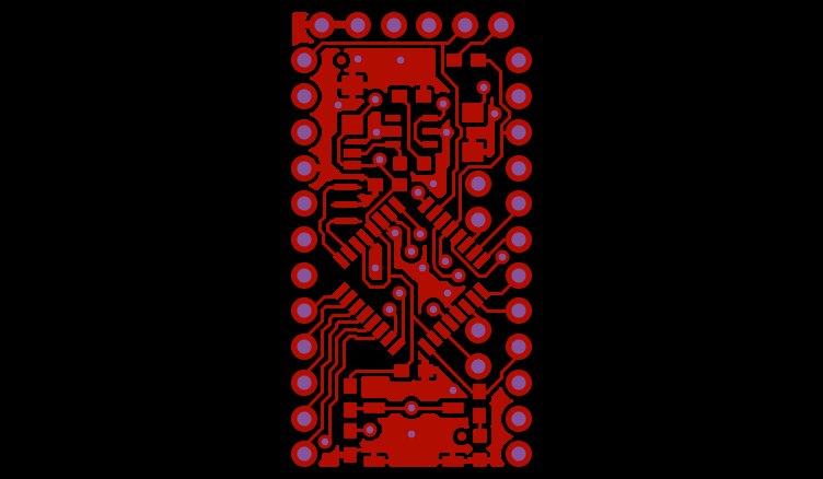
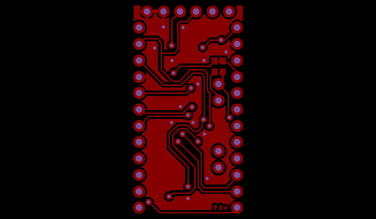
@NeverDie I've been playing with KiCAD and working with your BareBones_2AA_Arduino. Given the disucssion on the "Anyone using..." thread about ground planes it jumped out at me that your design uses no ground plane. Of course there isn't any room left either. Does that matter? I see that your radio boards, like the RFM69_900 have solid ground planes.
To look at further, I looked at the ProMini design by Sparkfun. Pictures are attached of the grounded fills they used. These pictures are of only the top and bottom copper for illustration. I'm thinking this would bother Eric Bogatin and he would say to throw in another layer dedicated to ground signal. Again, do you think it matters?
-
@NeverDie I've been playing with KiCAD and working with your BareBones_2AA_Arduino. Given the disucssion on the "Anyone using..." thread about ground planes it jumped out at me that your design uses no ground plane. Of course there isn't any room left either. Does that matter? I see that your radio boards, like the RFM69_900 have solid ground planes.
To look at further, I looked at the ProMini design by Sparkfun. Pictures are attached of the grounded fills they used. These pictures are of only the top and bottom copper for illustration. I'm thinking this would bother Eric Bogatin and he would say to throw in another layer dedicated to ground signal. Again, do you think it matters?
@Larson I think it probably does matter, but that a dipole antenna may be a good workaround to not having an optimal ground plane. I say that because a number of years ago a group of us on the lowpowerlab forum found that adding a dipole antenna to the rfm69 module resulted in a significant range improvement.
Part of the problem is that an optimally sized ground plane is actually quite large relative to an otherwise small mote, especially at sub-gigahertz frequencies. So, if you were to build an optimally sized ground plane into your PCB, your mote wouldn't be small anymore. Even a dipole antenna can be so large as to be cumbersome. This antenna: https://lowpowerlab.com/shop/product/193?search=dipole
was an outgrowth of the discussion and work that the group did, and, as you can see, it's not tiny. However, it might be feasible on a gateway, where size may not matter as much.So, short of that, should I try to add more ground plane? I really don't know. More is probably better, but I'm not smart enough to tell you how much difference a marginal increase would make. Adding a dipole antenna very definitely did make a noticeable difference though.
Maybe somebody reading this who knows more than me can comment.
Also, part of the reason I didn't add more groundplane was that it would negatively affect the current layout for the two 2.4Ghz horizontal trace antenna readios, which aren't supposed to be mounted over a ground plane. That could be rectified by moving the antenna module to the end of the board, where the trace antenna could hang off the end in empty space, but that's a version 2.0 design. Version 1.0 was just trying to get something ordered from a fab as quickly as possible, and the adapter board placement is something I would change for a v2.0. With that change, there'd be no reason not to do a copper pour and have a nice ground plane--well, within the mote's size constraints.
There's also more to it than just ground plane. There's the whole matter of impedance, which is hugely important. Smith charts, etc. I don't have more than a superficial grasp on how antennas are supposed to be designed, so I'm really the wrong person to ask about everything that's involved. From what I've read, even the particular dielectric that's used in your PCB can make a meaningful difference. Andreas Speiss did do an episode on how you can use a VNA to tune your antenna better. It might be worth a look. To me it looks like a very deep rabbit hole, and a very steep and very challenging learning curve, so it just depends how far down the rabbit hole you're willing to go. The way I see it, and maybe this is just me, I would hit diminishing returns almost immediately for the amount of effort that's required. That isn't to say that you shouldn't do it though. ;-)
-
@Larson Here's the list of nRF24L01 clones and variants: https://sigrok.org/wiki/Protocol_decoder:Nrf24l01
-
@Larson I think it probably does matter, but that a dipole antenna may be a good workaround to not having an optimal ground plane. I say that because a number of years ago a group of us on the lowpowerlab forum found that adding a dipole antenna to the rfm69 module resulted in a significant range improvement.
Part of the problem is that an optimally sized ground plane is actually quite large relative to an otherwise small mote, especially at sub-gigahertz frequencies. So, if you were to build an optimally sized ground plane into your PCB, your mote wouldn't be small anymore. Even a dipole antenna can be so large as to be cumbersome. This antenna: https://lowpowerlab.com/shop/product/193?search=dipole
was an outgrowth of the discussion and work that the group did, and, as you can see, it's not tiny. However, it might be feasible on a gateway, where size may not matter as much.So, short of that, should I try to add more ground plane? I really don't know. More is probably better, but I'm not smart enough to tell you how much difference a marginal increase would make. Adding a dipole antenna very definitely did make a noticeable difference though.
Maybe somebody reading this who knows more than me can comment.
Also, part of the reason I didn't add more groundplane was that it would negatively affect the current layout for the two 2.4Ghz horizontal trace antenna readios, which aren't supposed to be mounted over a ground plane. That could be rectified by moving the antenna module to the end of the board, where the trace antenna could hang off the end in empty space, but that's a version 2.0 design. Version 1.0 was just trying to get something ordered from a fab as quickly as possible, and the adapter board placement is something I would change for a v2.0. With that change, there'd be no reason not to do a copper pour and have a nice ground plane--well, within the mote's size constraints.
There's also more to it than just ground plane. There's the whole matter of impedance, which is hugely important. Smith charts, etc. I don't have more than a superficial grasp on how antennas are supposed to be designed, so I'm really the wrong person to ask about everything that's involved. From what I've read, even the particular dielectric that's used in your PCB can make a meaningful difference. Andreas Speiss did do an episode on how you can use a VNA to tune your antenna better. It might be worth a look. To me it looks like a very deep rabbit hole, and a very steep and very challenging learning curve, so it just depends how far down the rabbit hole you're willing to go. The way I see it, and maybe this is just me, I would hit diminishing returns almost immediately for the amount of effort that's required. That isn't to say that you shouldn't do it though. ;-)
@NeverDie said in Most reliable "best" radio:
so it just depends how far down the rabbit hole you're willing to go.
I'm deep in the rabbit hole already and its getting colder and darker. Thank you for your detailed discussion - especially the diminishing-return comment. Yea, I should focus on doing and reporting back - something to show for all I have learned. I remember the 6" dia ground plane idea. Yes, that is a deal-killer. I'd opt for sheet metal befoe building a PCB that big.
Again, Thank You!
-
Not completely sure yet, but going down the list of clones/variants datasheets, but it looks as though the amazon smd "nRF24L01" modules may be using the XN297 chip:
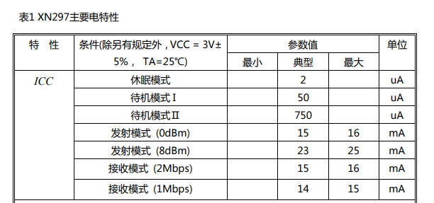
I suppose additional measurements, like sleep current and standby current, may either confirm it or not. Also, if it can't support 250kbps, that might also give it away.
According to the datasheet, it may go as high as 8dBm on Tx, so at least that would be consistent with the "enhanced power mode" advertising in the amazon.com listing. -
Well, I checked, and the mystery modules can do 250kbps, so evidently it is not the XN297. That was my best guess, and now I have no idea what it is. The sigrok list of clones and variants hasn't been updated in many years.
-
Well, I checked, and the mystery modules can do 250kbps, so evidently it is not the XN297. That was my best guess, and now I have no idea what it is. The sigrok list of clones and variants hasn't been updated in many years.
@NeverDie said in Most reliable "best" radio:
The sigrok list of clones and variants hasn't been updated in many years.
Yes, I saw the list of 2 originals and I counted 12 clone/variants. And that list was from 2015 and it is still instructive. If the chips are compatible and deliver value, then it is sufficent for those on the learning curve, like me. Probably not sufficient for market tested commercial products.
Fun to see the Nordic employee comment about a datasheet error that ended up in a clone. I remember that paper roadmap makers from 50-years ago, like Rand, used to deliberately make mapping errors to catch clones. Times have changed and methods haven't. The die comparisons referenced in links to your link are, again, mind blowing.
-
@NeverDie said in Most reliable "best" radio:
The sigrok list of clones and variants hasn't been updated in many years.
Yes, I saw the list of 2 originals and I counted 12 clone/variants. And that list was from 2015 and it is still instructive. If the chips are compatible and deliver value, then it is sufficent for those on the learning curve, like me. Probably not sufficient for market tested commercial products.
Fun to see the Nordic employee comment about a datasheet error that ended up in a clone. I remember that paper roadmap makers from 50-years ago, like Rand, used to deliberately make mapping errors to catch clones. Times have changed and methods haven't. The die comparisons referenced in links to your link are, again, mind blowing.
@Larson said in Most reliable "best" radio:
If the chips are compatible and deliver value, then it is sufficent for those on the learning curve, like me
I think that's the right attitude. The main difference, aside from differences in how they handle ACK (which most software now accommodates for) is that most clones/variants are not as energy efficient as the original. For instance, this particular clone, whatever it is, has a sleep current of something like 1.5ua-1.8ua, as opposed to Nordic's 0.7ua. So, that's worse, but it may not be a deal breaker.
The newer Nordic nRF5x series chips are definitely a lot more efficient at listening, with receive currents down in the 2.6ma-~5ma range when DCDC conversion is turned on. That compares very favorably to the 15ma and up of the nRF24L01/clones. Of course, a tradeoff is cost and, these days, availability. nRF52805 is "cheap" at around $4, and it's available, so at 4.6ma in RX, it's maybe not a bad choice, considering it includes an RTC and MCU. Its sleep current with RAM retention and RTC is an improvement over the prior nRF52840 flagship. The nRF52805's native Tx power is weak, but for listening it might be adequate. I think I'll order some to try.
The current flagship is the nRF5340, which is the one that has the 2.6ma Rx current. Presently it is the only one in the nRF53x series.
-
@skywatch said in Most reliable "best" radio:
That 'antenna modification' just looks crazy to me,
And that is why it will be fun to test. I corrected my post above and made comments on testing.
[Edit: It was my bad for drawing people down this dark alley of antenna modifications. I’ve learned much from dark allies and only been beaten-up a few times. Yet, I still go there… to learn. Therefore, I will test it and reply.]
-
@skywatch said in Most reliable "best" radio:
Yes it would, but positioning needs to be carefully maintained to avoid false results.
I think for a gateway it could make sense to use two nRF24L01 modules spaced a half wavelength apart. Then for reception you'd get all the benefits of antenna diversity, and for transmission to a particular node you could simply pick the module that receives the most packets out of the two from that node, which should give the better signal path. That could cut down on the sensitivity to positioning by better avoiding null zones.
@NeverDie I know what you mean, but "half a wavelength apart would have them in very close proximity with risk of interference. Better if the were 300mm+half a wavelenght apart. But can mysensors cope with 2 gateways on the same frequency? I didn't think that would be possible... Or were you thinking one gateway node with 2x RF modules? Now that would be interesting!