Most reliable "best" radio
-
@alphaHotel said in Most reliable "best" radio:
UPDATE:
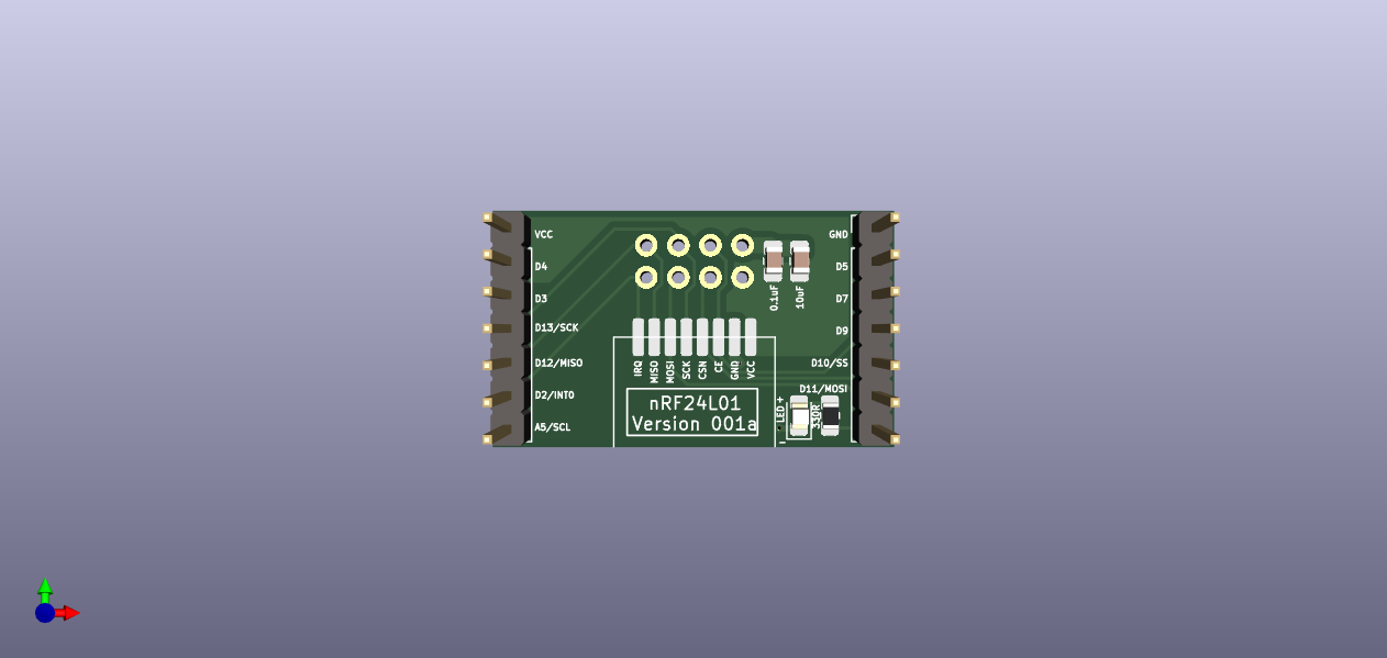
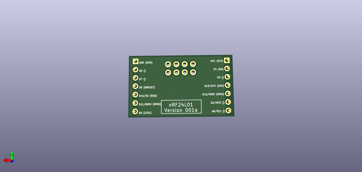
I've created a Github repo for my version of the nRF24L01 adapter board.
Thanks for the version. I have made a few tweaks to your version. I don't have an openhardware account, yet, but will make one when I have the time. In the meanwhile below are the pictures of my changes. In words:
- I shrank the frame of the board to minimize the interference with the TestPlatform neighboring pins
- rerouted two traces to make the ground plane cleaner
- moved some components as needed
@Larson said in Most reliable "best" radio:
I shrank the frame of the board to minimize the interference with the TestPlatform neighboring pins
Nice! How wide is that VCC trace/plane at its narrowest point now?
If you got it from Github, are you able to send me a pull request?
-
@NeverDie said in Most reliable "best" radio:
Adafruit's Clue device uses the KLJ-5030, which is 5mmx5mmx3mm:
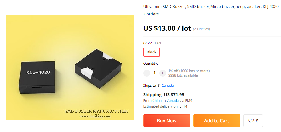
At higher cost I notice that there also exists a KLJ-4020, which is 4mmx4mmx2mmYikes! :flushed: Watch out for those shipping costs. Check my math, 4mm x 4mm x 2mm x 20 pcs = 640 cubic mm = 0.640 cubic cm = 0.0391 cubic inches, from China for $72 shipping? They must weigh a ton (or a tonne). LOL! :joy:
Seriously though, good find! I think I'll keep shopping around for a better price though. :grinning:
@alphaHotel said in Most reliable "best" radio:
@NeverDie said in Most reliable "best" radio:
Adafruit's Clue device uses the KLJ-5030, which is 5mmx5mmx3mm:
At higher cost I notice that there also exists a KLJ-4020, which is 4mmx4mmx2mmYikes! :flushed: Watch out for those shipping costs. Check my math, 4mm x 4mm x 2mm x 20 pcs = 640 cubic mm = 0.640 cubic cm = 0.0391 cubic inches, from China for $72 shipping? They must weigh a ton (or a tonne). LOL! :joy:
Seriously though, good find! I think I'll keep shopping around for a better price though. :grinning:
Yeah, the price is awful. I only linked it as an example. Looking a bit harder, I see they can be had for $1.53 each from a more reliable source: https://www.lcsc.com/product-detail/Buzzers_KELIKING-KLJ-4020_C556936.html The other thing to be wary regarding it is that the manufactures website says is only audible within a 0.5 to 1m range, which, if true, would be pathetically weak.
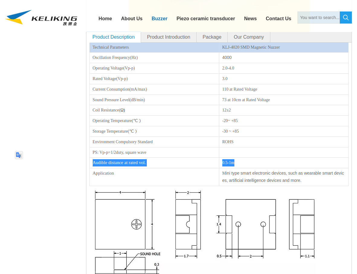
So, it has me thinking "close but no cigar."In comparison, having heard it myself, the KLJ-5030 is reasonably loud I would say.
-
Looks as though FUET has some good low-priced alternative buzzers:
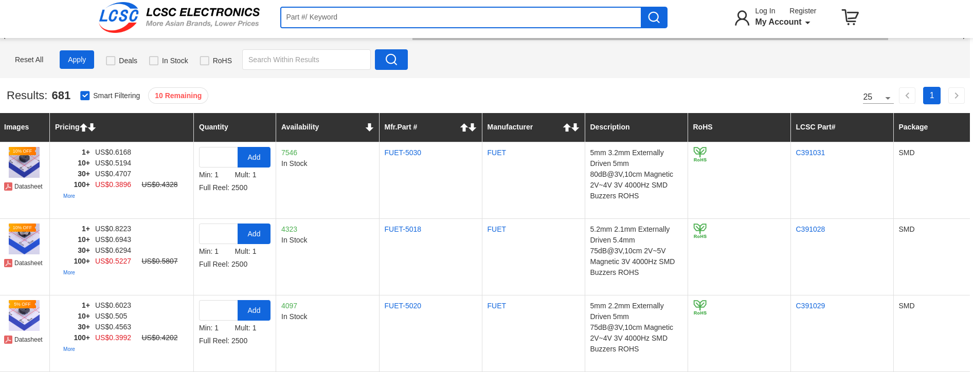
It must be something about the physics of buzzers that the thinnner they get in these small packages, the quieter they are. -
@Larson said in Most reliable "best" radio:
I shrank the frame of the board to minimize the interference with the TestPlatform neighboring pins
Nice! How wide is that VCC trace/plane at its narrowest point now?
If you got it from Github, are you able to send me a pull request?
@alphaHotel said in Most reliable "best" radio:
Nice! How wide is that VCC trace/plane at its narrowest point now?
KiCad tells me the narrowest VCC trace is about 0.045" (1.1 mm). I think the conventional 0.5 oz. copper is the common underlayment thickness. Is it too narrow? The return path is much narrower (Pin 1 nRF24L01). Does that matter?
@alphaHotel said in Most reliable "best" radio:
If you got it from Github, are you able to send me a pull request?
Yes, I think I got your version from Github. I will learn how to send a pull request. Cool, so this is how collaboration works? I'm new to this.
-
Looks as though FUET has some good low-priced alternative buzzers:
It must be something about the physics of buzzers that the thinnner they get in these small packages, the quieter they are.@NeverDie said in Most reliable "best" radio:
It must be something about the physics of buzzers that the thinnner they get in these small packages, the quieter they are.
I'm thinking of speakers of the 1970's: the drivers, midrange and tweeters would be nothing without the cabinet boxes. Does that apply here? In the 2010's these "soundbars" come into the picture. But there is still a box involved. Yes, it is probably about the physics of sonics... I'm thinking.
-
@alphaHotel said in Most reliable "best" radio:
Nice! How wide is that VCC trace/plane at its narrowest point now?
KiCad tells me the narrowest VCC trace is about 0.045" (1.1 mm). I think the conventional 0.5 oz. copper is the common underlayment thickness. Is it too narrow? The return path is much narrower (Pin 1 nRF24L01). Does that matter?
@alphaHotel said in Most reliable "best" radio:
If you got it from Github, are you able to send me a pull request?
Yes, I think I got your version from Github. I will learn how to send a pull request. Cool, so this is how collaboration works? I'm new to this.
@Larson said in Most reliable "best" radio:
Yes, I think I got your version from Github. I will learn how to send a pull request. Cool, so this is how collaboration works? I'm new to this.
Please don't add to your personal learning curve to create a pull request. It's not that important, at all.
-
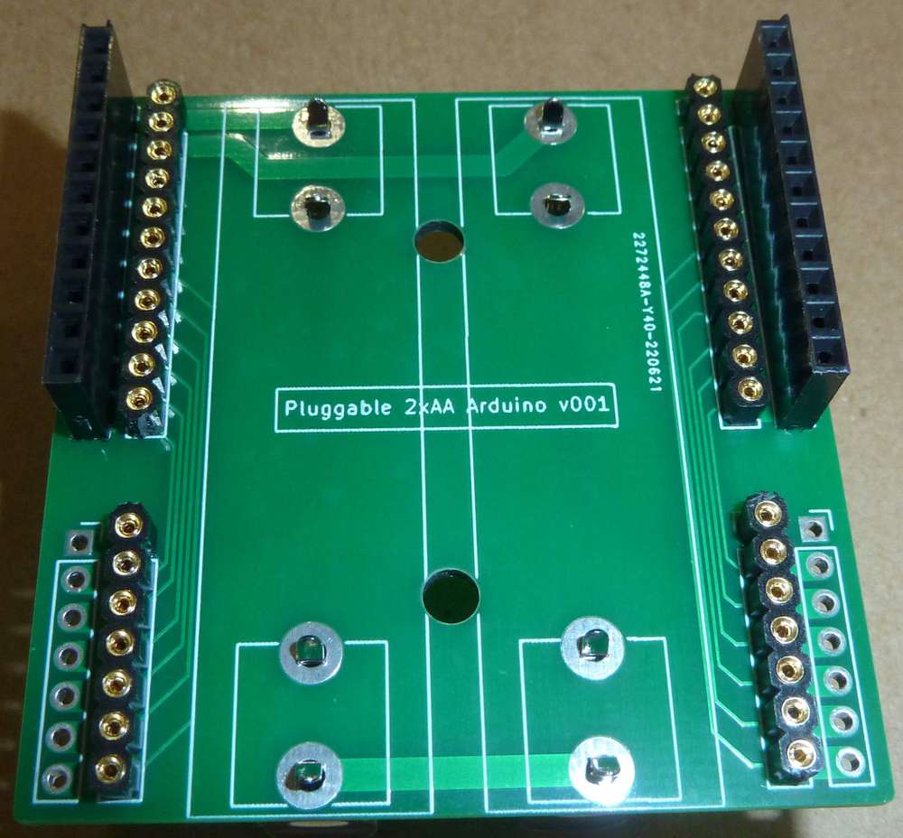
This is what I came up with for a platform that has both pluggable MCU's and pluggable radios:
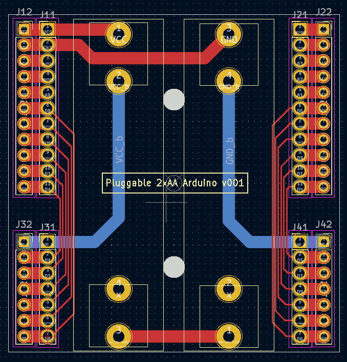
It's a bit wider than the previous test platform to give enough space between both the two AA batteries themselves and between those batteries and the pin headers. It also has a separate row of pins along the outside in case you want to have any shields that go on top. I did away with the switch entirely. Now if you want to power it off, you just remove a battery. So, doing all that renders the backplane/power-source very simple. Also, I included two mounting holes so that the whole thing can be mounted inside a project box. Yesterday I ordered this PCB along with a pluggable atmega328p MCU board and a pluggable radio board from a fab, so nothing physical to show-and-tell just yet.
@NeverDie said in Most reliable "best" radio:
This is what I came up with for a platform that has both pluggable MCU's and pluggable radios:
It's a bit wider than the previous test platform to give enough space between both the two AA batteries themselves and between those batteries and the pin headers. It also has a separate row of pins along the outside in case you want to have any shields that go on top. I did away with the switch entirely. Now if you want to power it off, you just remove a battery. So, doing all that renders the backplane/power-source very simple. Also, I included two mounting holes so that the whole thing can be mounted inside a project box. Yesterday I ordered this PCB along with a pluggable atmega328p MCU board and a pluggable radio board from a fab, so nothing physical to show-and-tell just yet.
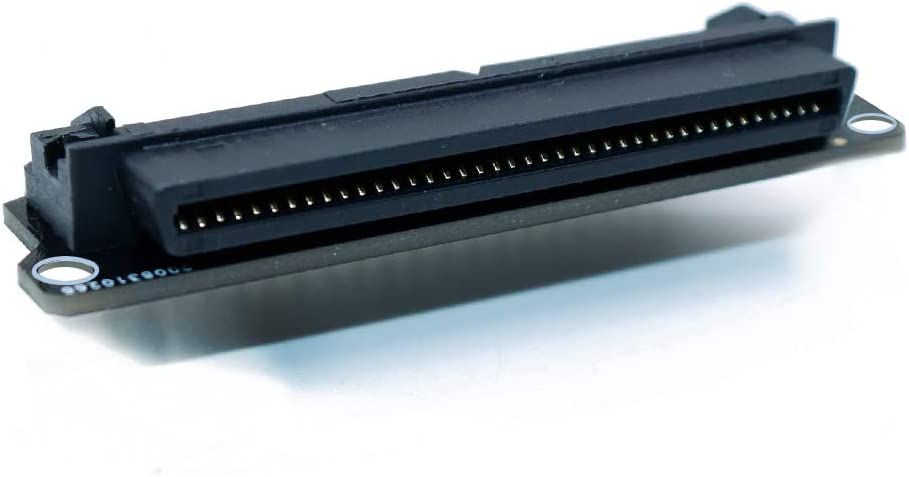
In terms of having "plugable" compute modules, I'm thinking that maybe edge connectors might be a good way to go. I say that because I've lately been looking at expansion slots for the Adafruit CLUE, which has a similar pinout to the BBC micro:bit. Even though those modules have only a little more than 20 pins to expose, some of the edge connectors on the market that are compatible with them can support as many as 80 pins! For a plugable compute module, the more pinouts the better. That way, if you need access to a lot more pins, you would simply plug the same compute module into a backplane that gives you access to a lot more pins to, for example, directly drive an LCD display instead of having to do it all (more slowly) using an SPI interface.
Well, that's all I've learned so far. I guess in the absence of any better ideas, maybe picking one of those 80 pin edge connectors that's compatible with micro:bit would perhaps be a worthwhile experiment to build a plugable backplane around. Especially for mcu's that come with a switchable fabric that can re-assign which logical pins are assigned to which physical pins, it would perhaps open up a lot of options for exploiting much more capable MCU's while still keeping the real estate small.
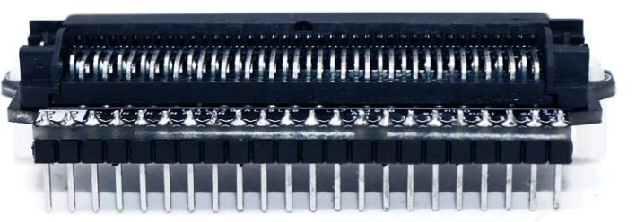
Here's an example of one of those 80 pin edge connectors that's micro:bit compatible: https://www.amazon.com/gp/product/B08HS27D51/ref=ox_sc_saved_title_3?smid=A22NPL1KB8AOV0&psc=1
as well as a PCB showing how it is wired for a micro:bit:
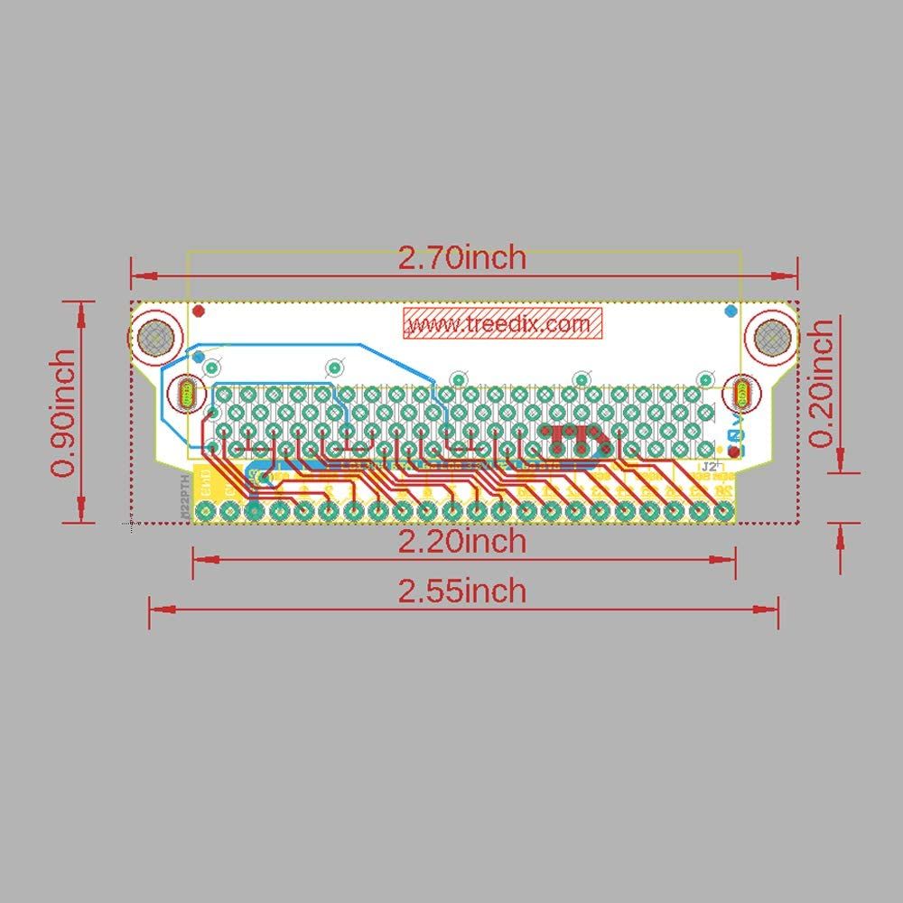
As you can see, lots of room to grow! The downside is that it's not small. Maybe an edge connector that's half as long would work well enough (though obviously sacrifice micro:bit compatability) and still keep things small. If there were a smaller, much higher connection density connector, that would obviously be better. Maybe @Larson 's idea of using zebra strips as connectors is more practical. Not sure. I suppose in a way the little aliexpress modules, with their array of contacts on the back of their little PCB's, are a type of connector, just not a plugable/unplugable one.Anyhow, I don't have the time to pursue it further at this juncture, so those are just some notes to either future self or to anyone who might want to tackle it. -
I was thinking of trying out the nRF52805, but it turns out making the nRF5 jump now isn't much easier than it was 5 years ago when I last looked into the nRF52 series. The main improvement in the interim is that certain popular chips, like the nRF52840 are now better supported, because they are baked into things like the Adafruit CLUE and have at least some familiar Arduino support.
-
@NeverDie said in Most reliable "best" radio:
This is what I came up with for a platform that has both pluggable MCU's and pluggable radios:
It's a bit wider than the previous test platform to give enough space between both the two AA batteries themselves and between those batteries and the pin headers. It also has a separate row of pins along the outside in case you want to have any shields that go on top. I did away with the switch entirely. Now if you want to power it off, you just remove a battery. So, doing all that renders the backplane/power-source very simple. Also, I included two mounting holes so that the whole thing can be mounted inside a project box. Yesterday I ordered this PCB along with a pluggable atmega328p MCU board and a pluggable radio board from a fab, so nothing physical to show-and-tell just yet.
In terms of having "plugable" compute modules, I'm thinking that maybe edge connectors might be a good way to go. I say that because I've lately been looking at expansion slots for the Adafruit CLUE, which has a similar pinout to the BBC micro:bit. Even though those modules have only a little more than 20 pins to expose, some of the edge connectors on the market that are compatible with them can support as many as 80 pins! For a plugable compute module, the more pinouts the better. That way, if you need access to a lot more pins, you would simply plug the same compute module into a backplane that gives you access to a lot more pins to, for example, directly drive an LCD display instead of having to do it all (more slowly) using an SPI interface.
Well, that's all I've learned so far. I guess in the absence of any better ideas, maybe picking one of those 80 pin edge connectors that's compatible with micro:bit would perhaps be a worthwhile experiment to build a plugable backplane around. Especially for mcu's that come with a switchable fabric that can re-assign which logical pins are assigned to which physical pins, it would perhaps open up a lot of options for exploiting much more capable MCU's while still keeping the real estate small.
Here's an example of one of those 80 pin edge connectors that's micro:bit compatible: https://www.amazon.com/gp/product/B08HS27D51/ref=ox_sc_saved_title_3?smid=A22NPL1KB8AOV0&psc=1
as well as a PCB showing how it is wired for a micro:bit:
As you can see, lots of room to grow! The downside is that it's not small. Maybe an edge connector that's half as long would work well enough (though obviously sacrifice micro:bit compatability) and still keep things small. If there were a smaller, much higher connection density connector, that would obviously be better. Maybe @Larson 's idea of using zebra strips as connectors is more practical. Not sure. I suppose in a way the little aliexpress modules, with their array of contacts on the back of their little PCB's, are a type of connector, just not a plugable/unplugable one.Anyhow, I don't have the time to pursue it further at this juncture, so those are just some notes to either future self or to anyone who might want to tackle it.@NeverDie said in Most reliable "best" radio:
Maybe @Larson 's idea of using zebra strips as connectors is more practical.
I learned about zebra strips from you - thank you very much. I was unable to re-establish connections for an existing commercial products and I don't know why. My thought was that zebra strips were some technology and complex signaling that is beyond my capacity. The device is probably over 20 years old. Therefore, I would not recommend zebra strips because I don't know enough about them.
This pic from your link is more telling of the capability of your referenced connectors.
 For now, I don't know why these are called edge-connectors. I thought edge-connectors were flat male blades with double-sided contacts that were fitted in sloted female gaps. The ones I think I've seen have an index slot for, I suspected, polarity protection and alignment. Maybe I've got this all wrong and they are called something else - like card connectors.
 -
@NeverDie said in Most reliable "best" radio:
Maybe @Larson 's idea of using zebra strips as connectors is more practical.
I learned about zebra strips from you - thank you very much. I was unable to re-establish connections for an existing commercial products and I don't know why. My thought was that zebra strips were some technology and complex signaling that is beyond my capacity. The device is probably over 20 years old. Therefore, I would not recommend zebra strips because I don't know enough about them.
This pic from your link is more telling of the capability of your referenced connectors.
For now, I don't know why these are called edge-connectors. I thought edge-connectors were flat male blades with double-sided contacts that were fitted in sloted female gaps. The ones I think I've seen have an index slot for, I suspected, polarity protection and alignment. Maybe I've got this all wrong and they are called something else - like card connectors.@Larson said in Most reliable "best" radio:
don't know why these are called edge-connectors.
@Larson I think they're called edge connectors because they mate with the edge of a PCB.
-
@Larson said in Most reliable "best" radio:
don't know why these are called edge-connectors.
@Larson I think they're called edge connectors because they mate with the edge of a PCB.
@NeverDie Yes, I think we are surfing the same wave. I'm thinking of a PCB mount that will recieve a perpendicular PCB board with double sided connectors like this: https://www.ebay.com/itm/122943051785?hash=item1c9ffa1809:g:daAAAOSwd4tTxdNW
Maybe there is an application of these for the radio modules that have the single row SMD mounting pads? One would need to ignore the opposing connectors. Better yet, maybe there are radio boards (?) that could be designed to slot in... just thinking. The NRF24’s would require double-sided 1x4 board and receivers. That would be cool and compact.
But then there is the ground-plane to think about?
-
CORRECTION: Earlier I said that Adafruit's TPL5110 breakout board appeared to use a 1M pulldown resistor on DONE. I remeasured today and that's wrong. It's actually a 10K resistor. So, since my adding a 10K resistor to that in parallel solved the issue of it not working, I today replaced Adafruit's 10K SMD resistor with a 5.1K SMD resistor. Afterward I retested, and I've confirmed that (not surprisingly) that works. So, with that modification to the Adafruit TPL5110 board, an external pulldown resistor is no longer needed. Not a big deal, but it keeps things a little tidier. As to what the optimal value should be, I don't know. I'm simply reporting that 5.1K seems to work and that Adafruit's choice of 10K didn't work in the two different test scenarios that I tried.
@NeverDie said in Most reliable "best" radio:
CORRECTION: Earlier I said that Adafruit's TPL5110 breakout board appeared to use a 1M pulldown resistor on DONE. I remeasured today and that's wrong. It's actually a 10K resistor.
Thanks for redirecting me to this thread. I think you were right on your original 1M Ohm assertion. Since I'm playing with my new TPL5110,s I took it on to make my own MM measurements. While my Harbor Freight MM might not be the most accurate instrument, I did show the resistance between DONE and GND to be 900 K'ish. Next, I got out the magnifying glass to spy the resistor in-line with said pins to have a marking of 1004. Google affirmed that that means 1 M ohm. So, your 5K, or 10K would be a big change – and if it comes at no cost for the quiescent current AND enables ESP action, then perfect!
-
@NeverDie said in Most reliable "best" radio:
CORRECTION: Earlier I said that Adafruit's TPL5110 breakout board appeared to use a 1M pulldown resistor on DONE. I remeasured today and that's wrong. It's actually a 10K resistor.
Thanks for redirecting me to this thread. I think you were right on your original 1M Ohm assertion. Since I'm playing with my new TPL5110,s I took it on to make my own MM measurements. While my Harbor Freight MM might not be the most accurate instrument, I did show the resistance between DONE and GND to be 900 K'ish. Next, I got out the magnifying glass to spy the resistor in-line with said pins to have a marking of 1004. Google affirmed that that means 1 M ohm. So, your 5K, or 10K would be a big change – and if it comes at no cost for the quiescent current AND enables ESP action, then perfect!
@Larson said in Most reliable "best" radio:
@NeverDie said in Most reliable "best" radio:
CORRECTION: Earlier I said that Adafruit's TPL5110 breakout board appeared to use a 1M pulldown resistor on DONE. I remeasured today and that's wrong. It's actually a 10K resistor.
Thanks for redirecting me to this thread. I think you were right on your original 1M Ohm assertion. Since I'm playing with my new TPL5110,s I took it on to make my own MM measurements. While my Harbor Freight MM might not be the most accurate instrument, I did show the resistance between DONE and GND to be 900 K'ish. Next, I got out the magnifying glass to spy the resistor in-line with said pins to have a marking of 1004. Google affirmed that that means 1 M ohm. So, your 5K, or 10K would be a big change – and if it comes at no cost for the quiescent current AND enables ESP action, then perfect!
I just now checked the adafruit schematic for the TPL5110, and you're right: it does show a 1 megaohm resistor. I guess I must have measured it wrong. https://github.com/adafruit/Adafruit-TPL5110-Power-Timer-Breakout-PCB
-
@alphaHotel said in Most reliable "best" radio:
E01-2G4M27D
I'm fairly certain the ones I ordered won't be arriving with antennas (as none were pictured in the aliexpress posting), but, no problem, I'll let you know for sure after they arrive. Most likely if you have an old wi-fi router that you no longer use, you could probably unscrew those antennas and use them, since they'd also be 2.4Ghz.
@NeverDie said in Most reliable "best" radio:
@alphaHotel said in Most reliable "best" radio:
E01-2G4M27D
I'm fairly certain the ones I ordered won't be arriving with antennas (as none were pictured in the aliexpress posting), but, no problem, I'll let you know for sure after they arrive. Most likely if you have an old wi-fi router that you no longer use, you could probably unscrew those antennas and use them, since they'd also be 2.4Ghz.
@alphaHotel Reporting back: I received them, and mine did not come with any antennas.
-
@NeverDie said in Most reliable "best" radio:
@alphaHotel said in Most reliable "best" radio:
E01-2G4M27D
I'm fairly certain the ones I ordered won't be arriving with antennas (as none were pictured in the aliexpress posting), but, no problem, I'll let you know for sure after they arrive. Most likely if you have an old wi-fi router that you no longer use, you could probably unscrew those antennas and use them, since they'd also be 2.4Ghz.
@alphaHotel Reporting back: I received them, and mine did not come with any antennas.
@NeverDie said in Most reliable "best" radio:
@alphaHotel Reporting back: I received them, and mine did not come with any antennas.
That's as I expected too because of the lack of any photos in the listings. Thanks for confirming, it's good to know. I do have a handful lying around from old WiFi routers as you mentioned.
-
I've had success getting the nRF24L01 to listen once per second for packets at an average current drain for just the nRF24L01 of 5.35ua. Not bad! The snag I'm running into though is that the listen window, encompassing power-up of the nRF24L01 through Rx mode is 1.6ms. However, if I use the atmega328p to time that 1.6ms, it raises the average current drain to 45ua, which is worse than my keyfinder keyfob's current drain (about 30ua on average). So....I need to find some way to sleep the atmega328p for 1.6ms in order to keep the total current drain low. However, how to do that? The TPL5111 has a minimum period of 100ms, so that's out. The atmega328p's WDT has a minimum period of 16ms, so that's out too. Unfortunately, the atmega328p has no built-in RTC. Even if I were to add an external RTC, I don't know of any that would let me dial-in 1.6ms.
Presently I can think of only two solutions:
-
Add some kind of external oscillator and feed it to Timer2 in asymchronous timer mode while sleeping the atmega328p. However, I can't seem to find from the datasheet what the current drain of that configuration would be, so it seems like a shot in the dark.
-
or, possibly use a GPIO pin to charge up an external capacitor and somehow calibrate the charging time so that when the capacitor discharges via some RC time constant it triggers a falling edge interrupt on the atmega328p to wake it up from sleeping after 1.6ms (the sleep time begins after it charges the capacitor). I haven't tried this, but it might actually work. It would notionally be kinda/sorta similar to how one can use an atmega328p to charge up a capacitor in order to determine the capacitor's capacitance value: https://www.norwegiancreations.com/2019/08/using-a-simple-arduino-to-measure-capacitor-value/.
If anyone has any other ideas on how to sleep an atmega328p for 1.6ms, please do post.
[Edit: Regarding #1, I suppose I could try measuring the sleep current with external asynchronous mode engaged but nothing connected to it. If it's acceptably low, I could then hook up an ultra low current 32.768K external crystal at an additional 500na or so. Hopefully there's some way tot turn everything off on the atmega328p except for the asynchronous counter. I'm doubtful as to whether I can apply such fine grained control like that to one of the sleep states (POWER_SAVE MODE), but maybe....? Here's some reason to be hopeful:
Power-save: is similar to the power-down mode, but the Timer2 is still awake and could be operated via an external clock.
https://wolles-elektronikkiste.de/en/sleep-modes-and-power-managementUgh. Except Timer2 is an 8 bit counter...., but that's OK: 1.6ms would be 53 ticks on a 32.768k oscillator, so at least that part should work if the mcu sets timer2 to overflow in 53 ticks and then go to sleep and if that overflow will trigger an interrupt to subsequently wake the mcu back up after 1.6ms.
Well, it's a plausible theory. Just need to test it!
Is it worth the effort though? Even if it worked, an nRF52 module would outperform this type of setup, would be more compact, would be easier/faster to assemble, and would (probably) be lower cost as well. Hmmmmm..... And the nRF53 will be even better hardware still, though the nRF53 does come with the extra overhead of an RTOS....]
-
-
I've had success getting the nRF24L01 to listen once per second for packets at an average current drain for just the nRF24L01 of 5.35ua. Not bad! The snag I'm running into though is that the listen window, encompassing power-up of the nRF24L01 through Rx mode is 1.6ms. However, if I use the atmega328p to time that 1.6ms, it raises the average current drain to 45ua, which is worse than my keyfinder keyfob's current drain (about 30ua on average). So....I need to find some way to sleep the atmega328p for 1.6ms in order to keep the total current drain low. However, how to do that? The TPL5111 has a minimum period of 100ms, so that's out. The atmega328p's WDT has a minimum period of 16ms, so that's out too. Unfortunately, the atmega328p has no built-in RTC. Even if I were to add an external RTC, I don't know of any that would let me dial-in 1.6ms.
Presently I can think of only two solutions:
-
Add some kind of external oscillator and feed it to Timer2 in asymchronous timer mode while sleeping the atmega328p. However, I can't seem to find from the datasheet what the current drain of that configuration would be, so it seems like a shot in the dark.
-
or, possibly use a GPIO pin to charge up an external capacitor and somehow calibrate the charging time so that when the capacitor discharges via some RC time constant it triggers a falling edge interrupt on the atmega328p to wake it up from sleeping after 1.6ms (the sleep time begins after it charges the capacitor). I haven't tried this, but it might actually work. It would notionally be kinda/sorta similar to how one can use an atmega328p to charge up a capacitor in order to determine the capacitor's capacitance value: https://www.norwegiancreations.com/2019/08/using-a-simple-arduino-to-measure-capacitor-value/.
If anyone has any other ideas on how to sleep an atmega328p for 1.6ms, please do post.
[Edit: Regarding #1, I suppose I could try measuring the sleep current with external asynchronous mode engaged but nothing connected to it. If it's acceptably low, I could then hook up an ultra low current 32.768K external crystal at an additional 500na or so. Hopefully there's some way tot turn everything off on the atmega328p except for the asynchronous counter. I'm doubtful as to whether I can apply such fine grained control like that to one of the sleep states (POWER_SAVE MODE), but maybe....? Here's some reason to be hopeful:
Power-save: is similar to the power-down mode, but the Timer2 is still awake and could be operated via an external clock.
https://wolles-elektronikkiste.de/en/sleep-modes-and-power-managementUgh. Except Timer2 is an 8 bit counter...., but that's OK: 1.6ms would be 53 ticks on a 32.768k oscillator, so at least that part should work if the mcu sets timer2 to overflow in 53 ticks and then go to sleep and if that overflow will trigger an interrupt to subsequently wake the mcu back up after 1.6ms.
Well, it's a plausible theory. Just need to test it!
Is it worth the effort though? Even if it worked, an nRF52 module would outperform this type of setup, would be more compact, would be easier/faster to assemble, and would (probably) be lower cost as well. Hmmmmm..... And the nRF53 will be even better hardware still, though the nRF53 does come with the extra overhead of an RTOS....]
Strikethrough
[Would 15 mseconds be close enough?
#include <LowPower.h>
LowPower.powerDown(0, ADC_OFF, BOD_OFF); //0 gives SLEEP_15MS,] Strikethrough[Edit - Sorry - on rereading is see the objective is 1.6 mS not 16 mS. I like your Timer suggestions - that is what they are for.]
-
-
I never realized you can send/receive BLE data using an nRF24L01:
https://www.youtube.com/watch?v=DGgjdBSId4YUnrelated to that,I found a nice introductory tutorial series on then nRF52:
https://www.youtube.com/c/SumairsEmbeddedEngineering/videosMost of the nRF52 stuff on youtube only considers either just the hardware or just the bluetooth aspects, but this series covers much more than just that. Lately Nordic's development has embraced the Zephyr RTOS, but this youtube series does not rely on Zephyr, which may (?) be good if you want tight control over the hardware without the overhead of an RTOS.
-
@NeverDie said in Most reliable "best" radio:
@alphaHotel said in Most reliable "best" radio:
@NeverDie With the first version of the battery/MCU board, you lamented running traces directly under the batteries. You have the space now to re-route them but choose not to. Did you find a way to resolve the issue it caused?
Actually, I fixed it on the new version (pictured above). The red traces run on top, so they're adequately isolated from the battery holder metal, which is on the back side except for the through-holes where it sticks through the board. Where I ran into trouble was running traces on the back side, beneath the battery holder metal. If the battery holder metal was pressed up hard against the board, some shorts resulted on some of the boards. The workaround was to not press the battery holder metal hard up against the board, but the new version removes that concern entirely.
Okay, I see now. I misunderstood the original issue and also didn't think about the top/bottom side orientation in relation to those traces vis-a-vis the battery holders. Thanks for clarifying.
@alphaHotel said in Most reliable "best" radio:
@NeverDie said in Most reliable "best" radio:
@alphaHotel said in Most reliable "best" radio:
@NeverDie With the first version of the battery/MCU board, you lamented running traces directly under the batteries. You have the space now to re-route them but choose not to. Did you find a way to resolve the issue it caused?
Actually, I fixed it on the new version (pictured above). The red traces run on top, so they're adequately isolated from the battery holder metal, which is on the back side except for the through-holes where it sticks through the board. Where I ran into trouble was running traces on the back side, beneath the battery holder metal. If the battery holder metal was pressed up hard against the board, some shorts resulted on some of the boards. The workaround was to not press the battery holder metal hard up against the board, but the new version removes that concern entirely.
Okay, I see now. I misunderstood the original issue and also didn't think about the top/bottom side orientation in relation to those traces vis-a-vis the battery holders. Thanks for clarifying.
I received the PCB today, and I think I see now the source of your confusion: I had put the silkscreen outline for the battery and its clips on the FRONT instead of on the BACK where it belongs. I'll correct it on the next iteration. On this first iteration I'm mainly just testing for fit and to make sure the space is such that the battery clips don't short against either themselves or against the headers. I'll also be adding polarity markers as a reminder for the correct way to insert the batteries.
-
Here's the first pass on the new version:
The good news:
-
I widened the separation between the batteries, and now the clips aren't at risk of shorting against one another.
-
list itemThe machine pins now sit nice and low against the PCB. The idea is that this way a shield can arch overhead without having to add much to the overall height. That's why I have regular headers on the outside part.
Not so great: as a guard against shorting against the clips, I maybe overcompensated by overwidening the headers as well. I think I can probably narrow the overall board width by 3 to 6mm and still have adequate clearance. I'll do some more iterations until I zero in.
Also, unlike the earlier test platform, this board lacks a way to separate out current measurement to the radio vs to the mcu. Since I already have the test platform for that, I don't think I care, but maybe someone else would want that? It could be added to the backplane, or it could be added to the plug-in modules themselves.
Lastly, I'm noticing that the battery clips fit so tightly against the PCB holes that you probably don't even need to solder them! ;-)
-